[PROBLEM/SOLUTION] Suggested backboard mounting of KSU
34 views
Skip to first unread message

Greg Ercolano
Nov 25, 2019, 2:12:32 PM11/25/19
to seriss-...@googlegroups.com
> Do you have any suggestions/details on how to mount the 1A2
KSU board to a backboard?
Sure -- this is covered somewhat in the manual, but I can add a few details for mounting the KSU to phone closet backboards.
Use Fire Rated Wood or Paint for Backboards
Local building codes vary, but you should always consider using fire retardant wood, and be sure to leave the stamp on the wood /visible/ to an inspector. (For instance, if you sell your house with a backboard installed, the buyer's inspectors may flag this if it's not visible. Or at very least use a fire retardant coating. For some example information, here's excerpts from a relevant discussion entitled "Backboard Code" on this page of the Sundance Communications telecom "Cabling" forum:
(Silversam) Refer to the ANSI/EIA/TIA Building Telecom Wiring Standard on how to wire a telecom closet. For example, the following from a 1999 edition of the EIA/TIA "A minimum of two walls should be covered with rigidly fixed 3/4" plywood.....Plywood should be either fire rated or covered with two coats of fire retardant paint."
(hbiss) "The backboard should always be installed over the sheetrock. The sheetrock provides fire resistance."
(mikeydidit) "Here in our hospital environment we are required to apply two coats and place a sticker on the backboard from the manufacture of the paint. It gives the type of paint (FIRE rated)"
(oldtimerbob) "In some areas the inspector wants to see the 'fire-rated' stencil that comes on the plywood from where ever you get it from,so we normally leave it unpainted.(the stencil that is) On the paint, you can leave the label or a copy of it (like a snapshot) for the inspector too."
(Frank_DaFoneguy) "The inspector told me two coats of latex paint is ok for "fire resistance" since wood only holds up for 1 hour rating when painted."
Position KSU Based On 25 Pair Cable Routing
Position the KSU on the backboard such that the best clearance for the (4) 25 pair cables can come off the 4 extension connectors nicely. Leave room for strain relief/tie downs just below the board if needed.
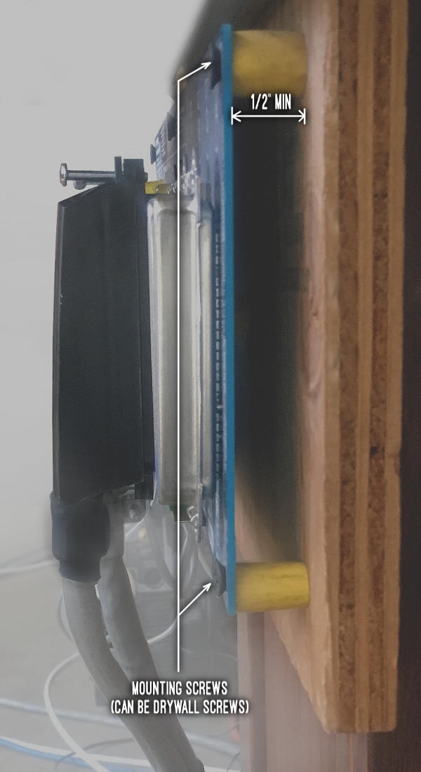
Use Standoffs and 1/2" Clearance
When mounting the backboard, you can use drywall screws to mount. Be sure to use all 7 screw holes provided on the board for proper mounting! The ensures the board doesn't stress and bend the board during plugging/unplugging of the large amphenol connectors.
Use 1/2" standoffs for each screw to space the board off the backboard. You can use most non-conductive spacers as the standoffs for each of the 7 screws: rubber, nylon, or even stripping the round insulation from an old AC power cord:
Using fingers or needle nose pliers, hold the insulation in place under the board, and drive each screw through the board and standoff into the backboard until slightly firm. Don't over tighten, or you can crack the board.
When installed with standoffs, the board should look something like this:
25 Pair Cable Strain Relief
If you don't have access to the proper cable management hardware to strain relieve the 25 pair cables (so they don't pop out from accidental cable yanks) and need to improvise, here are a few suggestions:
* Mount a screen door handle to the backboard below the KSU's extension connectors with short screws, and route the cables through it, tie-wrapping as needed. Or..Frame KSU To Protect From Falling Debris/Dirt
- or -
* Mount 4 drywall screws below the board, one for each cable, near where the cables fall from the board, to act as a "cable comb". Use approx 1" standoffs (or rubber cord insulation) over each screw so when you tie-wrap the cables to the screw, the cable is protected from the screw's sharp threads by the standoff/insulation.
- or -
* Sometimes just tie-wrapping the 25 pair cables together just below the KSU makes a stiff enough structure out of the cable to keep them from being pulled off accidentally, distributing any strain on one cable to all 4 connectors.
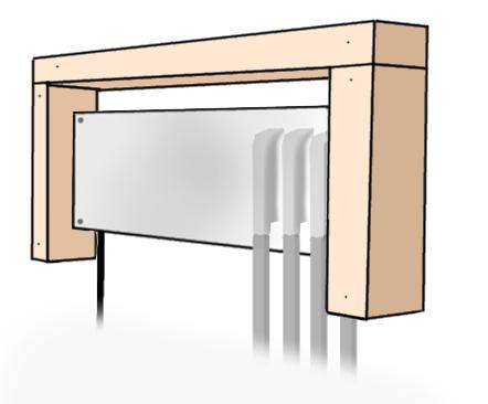
You don't have to do this, but if you expect your backboard to be actively modified, you may want to protect the bare KSU board from wire clippings and stray falling screws/nuts.
Some people mount a metal cover over the card. This is fine as long as airflow isn't hindered to allow for heat dissipation; punch holes along the top and bottom to allow simple heat convection.
Or, a simpler solution is to build a simple small wood frame around it to act as a 'roof' to catch any falling debris. Such a frame should stick out a good 1" beyond the top of the board. So to allow for the board spacers, use at least a 2" thick frame. Leave only the bottom un-framed, to allow cables to fall off freely. Adhere to the above fire retardant suggestions for the frame's materials (fire retardant wood or paint):
Mounting the PowerDSINE Ring Generator or a 118A Ring Generator
The small PowerDSINE ring generator module and/or 118A usually do not have any kind of mounting provisions, making it a little awkward to mount to the backboard.
Resist the urge to let the PowerDSINE just dangle by the wires from the KSU 6 pin connector. Position the device where you want it, then using a screw gun, put one long drywall or deck screw positioned around each of the 4 corners of the device to keep it positioned tightly. If need be, add a long tie-wrap around all 4 screws, but usually just the 4 screws are enough:
By using drywall screws, it's easy to unscrew to allow for relocation when backboard components need to be moved around.
Another technique recommended is to use 3M double sided foam sticky tape. You can buy these as little squares or in rolls of tape you cut from hardware stores (e.g. Home Depot).
This works as well, but if you mount the foam directly to the backboard, it's not easy to relocate. If you go the double sided foam tape route, I advise mounting it to a small piece of scrap backboard wood first. Then you can screw that piece to the backboard, so that it can be unscrewed and moved easily:


Reply all
Reply to author
Forward
0 new messages