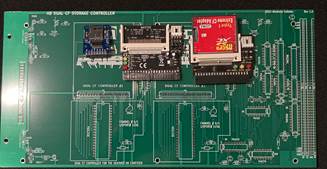
H8-Dual-CF Controller for HDOS!

norberto...@koyado.com
I’m still waiting for DHL to deliver such board by next week or earlier. These are the boards from JLCPCB.COM.

Thanks,
Norberto

Richard Davis Jr.
--
You received this message because you are subscribed to the Google Groups "SEBHC" group.
To unsubscribe from this group and stop receiving emails from it, send an email to sebhc+un...@googlegroups.com.
To view this discussion on the web visit https://groups.google.com/d/msgid/sebhc/017301d853aa%24be14ce90%243a3e6bb0%24%40koyado.com.
norberto.collado koyado.com

Sent: Tuesday, April 19, 2022 3:10 AM
To: se...@googlegroups.com <se...@googlegroups.com>
Subject: Re: [sebhc] H8-Dual-CF Controller for HDOS!

Glenn Roberts
When it rains it pours! Seems like every day there’s a new board arriving!
To view this discussion on the web visit https://groups.google.com/d/msgid/sebhc/SN6PR01MB38558765E6477889DDA86E27F7F29%40SN6PR01MB3855.prod.exchangelabs.com.
Richard Davis Jr.
To view this discussion on the web visit https://groups.google.com/d/msgid/sebhc/04fa01d85420%2474f94710%245eebd530%24%40gmail.com.
norberto.collado koyado.com
Sent: Tuesday, April 19, 2022 12:05 PM
To: se...@googlegroups.com <se...@googlegroups.com>
Subject: RE: [sebhc] H8-Dual-CF Controller for HDOS!
Glenn Roberts
For me the nightmare is always ordering the parts. I know many of you keep a lot of parts on hand but I pretty much order based on the board I’m building. I keep a small collection of passive components of course, but the ICs are pretty much ordered based on need. Almost never can get down to a single vendor – often need multiple vendors (especially with today’s supply-side issues). Even with the Bill of Materials I often have to spend multiple hours putting together the orders. Of course, once a board is up and running it’s all worth the effort!
To view this discussion on the web visit https://groups.google.com/d/msgid/sebhc/SN6PR01MB3855C2F7985C220D0D549A0FF7F29%40SN6PR01MB3855.prod.exchangelabs.com.
norberto.collado koyado.com
norberto...@koyado.com
Hello Rick,
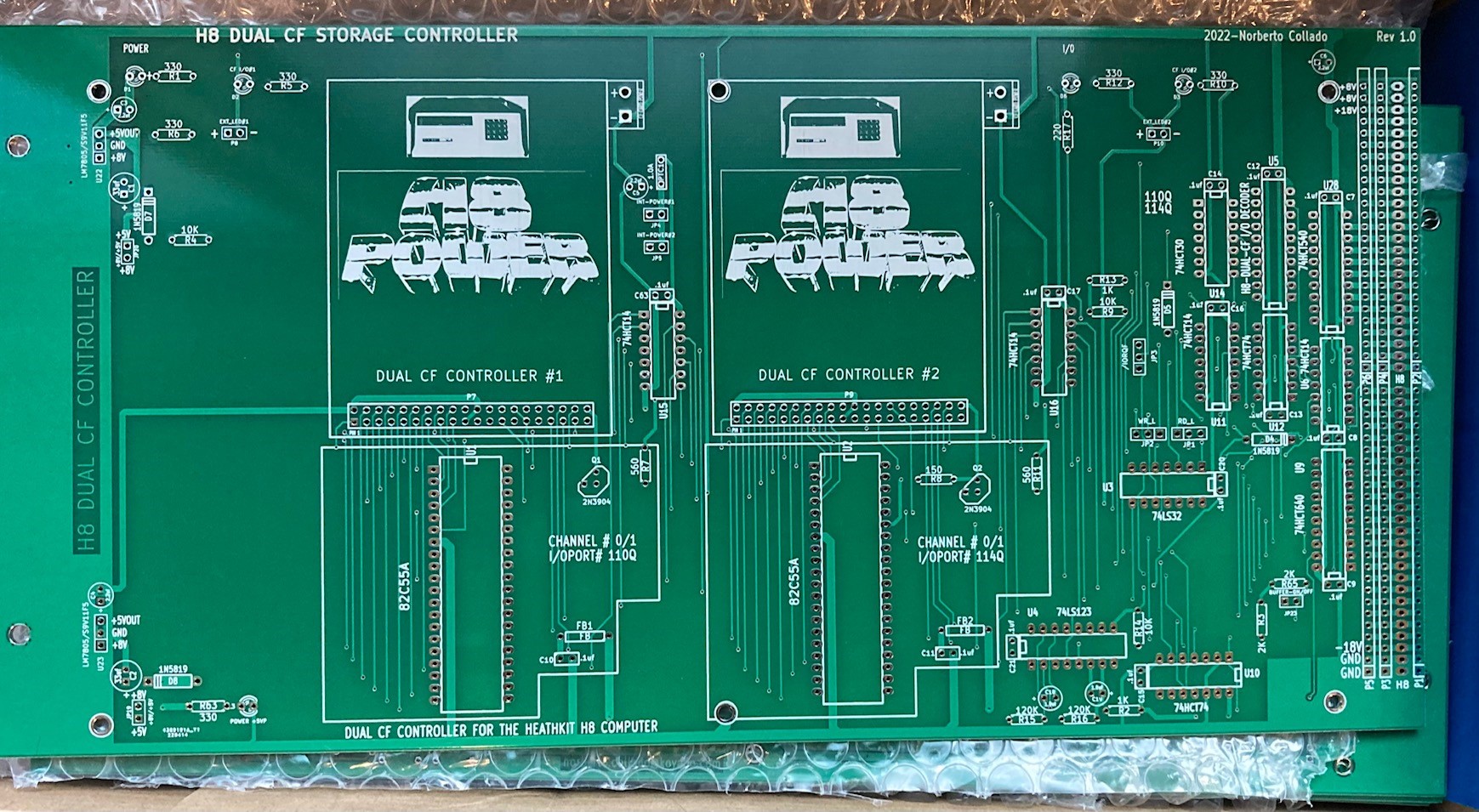
The H8-Dual-CF controller is here and it looks great. Attached is a picture of the board.
Even, I have not tested it yet, can I send you one, or do you prefer to wait? Which parts you do need?
Thanks,
Norberto

Douglas Miller
Richard Davis Jr.
Douglas Miller
Hi Rick,
I'm assuming you are talking about the HDOS driver. Or at least you are not talking about the CP/M 3 driver. I'm interested to see the schematic so I can model an emulation and work on the CP/M 3 and MP/M drivers, as well as the boot code for the new monitor ROM.
Thanks,
Doug
--
You received this message because you are subscribed to the Google Groups "SEBHC" group.
To unsubscribe from this group and stop receiving emails from it, send an email to sebhc+un...@googlegroups.com.
To view this discussion on the web visit https://groups.google.com/d/msgid/sebhc/2f5881ff-f94c-4970-a2f6-f358fb9b9642n%40googlegroups.com.

Terry Smedley
Douglas Miller
Thanks, I had not read the memo on the new web site! (probably got it, just neglected to read it).
Looking at the schematic, I see that this is not really a CF
interface, but rather an IDE interface. Is it being restricted to
16-bit IDE transfers, or is the CF 8-bit mode allowed? It also
appears that the data strobes are bit-banged through the 82C55?
What mode is the 8255 to be operated in? This would prohibit use
of Z80 block-I/O instructions and cut the data transfer rates
considerably.
I realize that I'm past the "speak now or forever hold your peace" stage. I guess I should not have made assumptions about this when it was being designed.
To view this discussion on the web visit https://groups.google.com/d/msgid/sebhc/d80d62d6-b9f0-4542-9928-ee304d7320ean%40googlegroups.com.
Richard Davis Jr.

Joseph Travis
To view this discussion on the web visit https://groups.google.com/d/msgid/sebhc/2c697886-bdc4-4db3-9df9-4ecd4ee7617cn%40googlegroups.com.
Douglas Miller
OK, I will not plan on providing support for this board. Renegotiation is possible, but may require top-shelf bourbon.
To view this discussion on the web visit https://groups.google.com/d/msgid/sebhc/2c697886-bdc4-4db3-9df9-4ecd4ee7617cn%40googlegroups.com.
norberto.collado koyado.com
Sent: Wednesday, April 20, 2022 10:14 AM
To: se...@googlegroups.com <se...@googlegroups.com>
Subject: Re: [sebhc] H8-Dual-CF Controller for HDOS!
OK, I will not plan on providing support for this board. Renegotiation is possible, but may require top-shelf bourbon.
norberto.collado koyado.com
Sent: Wednesday, April 20, 2022 10:07 AM
To: se...@googlegroups.com <se...@googlegroups.com>
Subject: Re: [sebhc] H8-Dual-CF Controller for HDOS!
Joseph Travis
To view this discussion on the web visit https://groups.google.com/d/msgid/sebhc/SN6PR01MB3855CD52E97DDAC53256204CF7F59%40SN6PR01MB3855.prod.exchangelabs.com.
Douglas Miller
Yes, no one ever asked me to work with this board. I was just
projecting... I mistook this board as a replacement for earlier,
similar, boards.
As far as "modern" storage on the H8, we seem to have two main
technologies: CF and (micro)SD. We have a plan for SDCard in the
works. If the GIDE board is remaining an active product, then
perhaps we have both covered. I don't see a need to keep
re-inventing new ways to connect solid-state storage to the H8.
Unless there's a problem with the GIDE.
I suppose one could argue that SAS/SATA is another, but I'm not
sure we need to go that far. Then there's NVMe, which I also don't
think we need to try. These are just too complex for an 8-bit
system, IMHO.
To view this discussion on the web visit https://groups.google.com/d/msgid/sebhc/SN6PR01MB3855CD52E97DDAC53256204CF7F59%40SN6PR01MB3855.prod.exchangelabs.com.
Richard Davis Jr.
Richard Davis Jr.
Douglas Miller
I'd be curious about how an IDE-SDCard adapter works. The SDCards
are SPI or at least some hybrid serial/parallel (2 or more serial
"lanes") interface. Also, the SDCards do not work on the ATA
command spec. Is there a micro-controller on this adapter?
To view this discussion on the web visit https://groups.google.com/d/msgid/sebhc/a157bd76-e803-4fa1-95ac-00d4dabe721dn%40googlegroups.com.
Richard Davis Jr.
norberto.collado koyado.com
Sent: Wednesday, April 20, 2022 11:16 AM
To: SEBHC <se...@googlegroups.com>
Douglas Miller
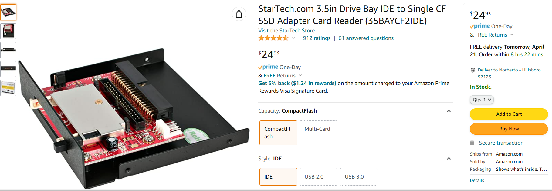
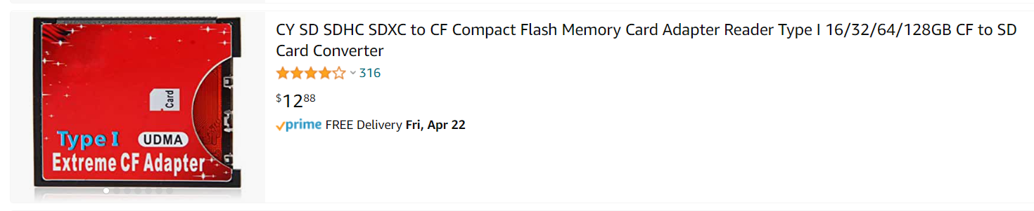
So things like these?
Interesting, I didn't know they existed. Will be interesting to see how well they work.
To view this discussion on the web visit https://groups.google.com/d/msgid/sebhc/cc1ce7f9-4685-4ad4-9bc8-1147b4ce531cn%40googlegroups.com.
norberto.collado koyado.com
Sent: Wednesday, April 20, 2022 11:57 AM
norberto.collado koyado.com

norberto.collado koyado.com
Sent: Wednesday, April 20, 2022 12:34 PM
norberto.collado koyado.com
Douglas Miller
Just looking at the binary image, the ROM is completely full.
Hard to say for sure how much space can be reclaimed from H47.
There is a little space for padding to specific addresses that
might be used. It really depends on what the code is like to boot
from this device (how large it is).
To view this discussion on the web visit https://groups.google.com/d/msgid/sebhc/SN6PR01MB38558D2D0A27D6D2CAA7DFE9F7F59%40SN6PR01MB3855.prod.exchangelabs.com.
norberto.collado koyado.com
Douglas Miller
Curious about one thing related to the Dual GIDE board. I
understand that Terry G's GIDE Z80-piggyback requires a Z80, but
your Dual GIDE board operates off the H8 bus, right? It should
work with any CPU?
To view this discussion on the web visit https://groups.google.com/d/msgid/sebhc/SN6PR01MB3855B17B257C29DD3C371B6CF7F59%40SN6PR01MB3855.prod.exchangelabs.com.
Norby
On Apr 20, 2022, at 1:50 PM, Douglas Miller <durga...@gmail.com> wrote:
To view this discussion on the web visit https://groups.google.com/d/msgid/sebhc/62e18a35-bed1-031b-2a96-70e587cff1a1%40gmail.com.
Douglas Miller
Well, I'm not suggesting anything. It just seems like it's a piece of existing hardware that works for all CPUs and supports two IDE channels (4xCF cards), and we already have code for it. I'm not sure what was done for HDOS and the GIDE, but even if it were written with Z80 instructions it's not too bad to convert back to 8080 (with expected performance loss). I also have not looked at the XCON8 GIDE code, but even if it is not for the same I/O port address, it should be easy to fix.
That doesn't help Rick get his board booting, though.
To view this discussion on the web visit https://groups.google.com/d/msgid/sebhc/03392C65-2D35-4541-95F5-3FF1C82C9595%40koyado.com.
Richard Davis Jr.
To view this discussion on the web visit https://groups.google.com/d/msgid/sebhc/9cd4aa0e-b7f3-3e5a-47a1-c20529763158%40gmail.com.
Douglas Miller
I was getting myself confused again about IDE. Looking at the
GIDE schematic and ATA-1 specification, it looks like the "Dual
GIDE" board is actually one IDE channel with a maximum of two
drives (CF cards). Is that correct? It just "presents" those two
drives as two separate connectors (for convenience of plugging in
CF cards)?
Ricks board, though, seems to be two IDE channels and could potentially support 4 drives?
In neither case can a CF card be connected without the IDE-CF adapter, right?
To view this discussion on the web visit https://groups.google.com/d/msgid/sebhc/CABvWWgb6tGg-80Mj-R8ZXxG_5vwAJ1dYjp%2BkmpS7kmKPSGhemQ%40mail.gmail.com.
Richard Davis Jr.
To view this discussion on the web visit https://groups.google.com/d/msgid/sebhc/4643d0e8-da4c-ae5a-e1a1-8a60c920fe7d%40gmail.com.
Douglas Miller
Right, the adapters have no active components on them. But they do map signals to a different connector with a different pinout. I've also heard that it is possible to get "unreliable" adapters, for whatever reason. But you still have to connect a CF socket adapter to the IDE plug, and need to anchor that to the main PCB if you don't want wobble. As opposed to soldering a CF socket on the PCB directly. That would also eliminate any need to acknowledge IDE at all, for example as done by the RC2014 board - in fact it is strictly an 8-bit mode board, which makes perfect sense since we're talking about 8-bit CPUs with 8-bit data buses anyway.
To view this discussion on the web visit https://groups.google.com/d/msgid/sebhc/CABvWWgYHUHhSNC5adzf8eHAfKefJw1O1Oq-S0%2Bn-5U-2_pevtA%40mail.gmail.com.
norberto.collado koyado.com
Douglas Miller
There are thru-hole sockets available... one at digiKey:
https://www.digikey.com/en/products/detail/samtec-inc/CFT-125-01-L-D-RA-01-SL/6677950
I think the schematic would be based on whatever they do for the IDE-CF adapters. We'd just route the appropriate IDE signals to the pads on the CF-socket footprint. I've not found one that published a schematic. I did find this:
https://allpinouts.org/pinouts/cables/data_storage/ide-to-compactflash-cf-adapter-schematic/
Have not looked through these connections in-depth.
I'm not trying to force any changes here, but just bring it up
for discussion. It just seems as though (based on the RC2014
design) it is reasonable to connect a CF card in a "8-bit only"
configuration, which would eliminate a lot of components, GALs,
etc. If it is reasonable to eliminate the option of connecting an
IDE spinning HDD (can you even buy new ones anymore? There might
be SSDs). If IDE doesn't really give us anything, seems to me we
could live with CF-only just fine. Of course, the boards are
already designed, so I'm not keen on making extra work or waste.
To view this discussion on the web visit https://groups.google.com/d/msgid/sebhc/SN6PR01MB3855B0C6C5978B04393B0275F7F59%40SN6PR01MB3855.prod.exchangelabs.com.
Norberto Collado
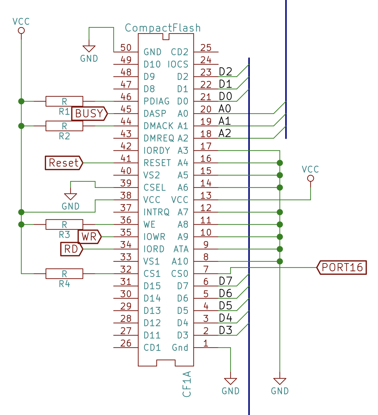
This is cool Douglas having the thru-hole sockets, thank you. I was looking at the RC2014 schematic and they short to ground the address lines, except A2-A0. How much storage can you get out of this configuration? How this works?
Thanks,
Norberto
Error! Filename not specified.
To view this discussion on the web visit https://groups.google.com/d/msgid/sebhc/e091b2d4-045f-9a0c-7fbf-116b58d1dd2c%40gmail.com.
Norberto Collado
Analyzing the RC2014 schematics, all the signals are on the 82C55, so we just take it out for now the 82C55 and insert a board with such CF connector and done, to prototype it. Just like Terry S. did for the I2C IC.
Douglas Miller
Yes, it might be that simple - to prototype.
The address lines, at least in the mode we use, are for register select. Only the bottom 3 are used. I'm no expert at the CF specification, so I'm not sure why those higher address lines even exist. I seem to recall something about the standard PC I/O address being decoded there. Storage is accessed through the LBA in the commands, so we have more than 16 bits (i.e. 28 bits). CS1 is tied high as the two "extra" registers accessed by that aren't really needed, or at least not usually. That means they only need 8 ports instead of the 16 for GIDE. Although, if you want to support more than 2 CFs then you'll need some sort of selector port (or another 8-port range). Like you did with the IDE sockets, CSEL will need to be "0" and "1" on the ports to select drive 0 and 1.
To view this discussion on the web visit https://groups.google.com/d/msgid/sebhc/EAEA0027-3737-4B7A-9602-5ACFAF553167%40koyado.com.
Norberto Collado
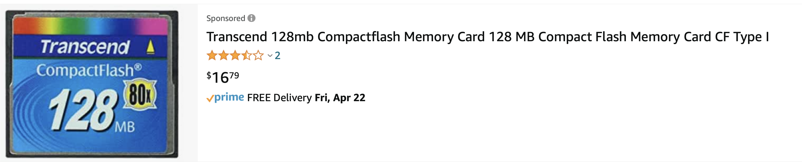
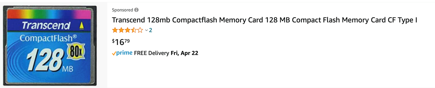
I got it now. It is using 8 bit mode and a maximum of 128MB will be available. For CP/M a 128MB card is split in to 15 x 8MB drives and 1 x 2MB drive. That should work fine for Quikdata boot loader.
4x128 = 512MB max.
At least we can still buy the 128MB from Transcend at $16+.
To view this discussion on the web visit https://groups.google.com/d/msgid/sebhc/EAEA0027-3737-4B7A-9602-5ACFAF553167%40koyado.com.
Douglas Miller
I'm not finding any restriction on storage capacity in 8-bit
mode. You still have 28 bits for the LBA, which should be 128GB.
The version of CP/M being run may have limitations, like 16x8MB
partitions = 128MB. The CP/M I saw has hard-coded DPBs using the
first ~128MB of the CF. But, software in general should be able to
access 128GB as far as I know.
To view this discussion on the web visit https://groups.google.com/d/msgid/sebhc/C63385C4-A762-4C08-909E-70F8BBF5E79A%40koyado.com.
Norberto Collado
I'm not finding any restriction on storage capacity in 8-bit mode. Much better and thank you for the clarification. I will order today the right angle socket and will use the H8-Dual-CF controller to add such connector. Which I/O address can you use to boot at least CP/M3 on the Z80 v4 board for POC?
To view this discussion on the web visit https://groups.google.com/d/msgid/sebhc/2c3002da-63e9-ec00-d2ce-81ed9cc658f2%40gmail.com.
Norberto Collado
Ordered parts + other pending parts.
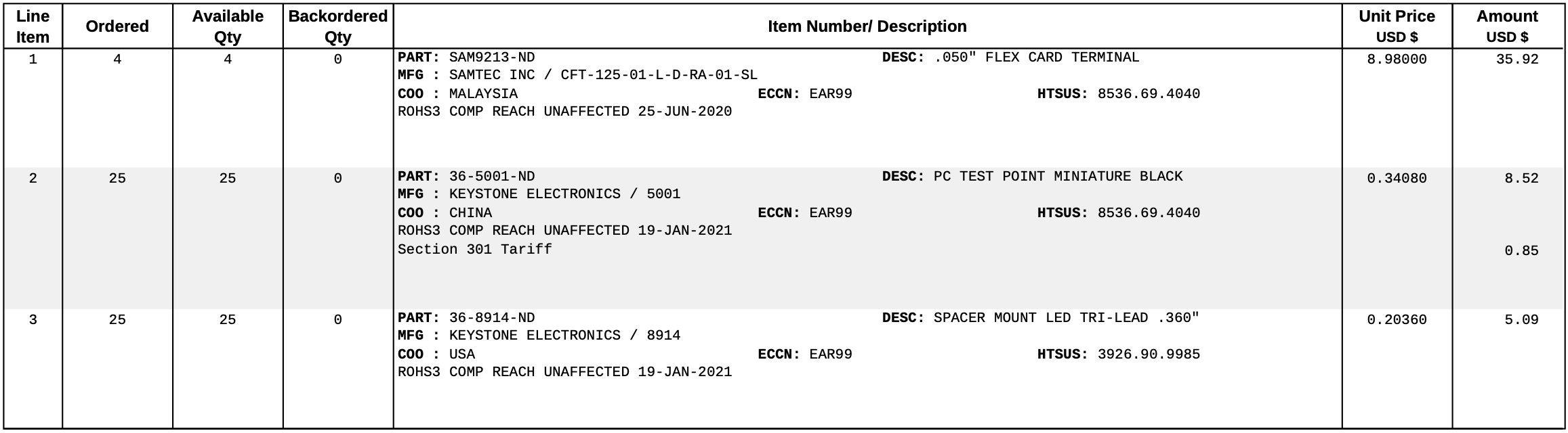
Douglas Miller
So, the GIDE put the standard CF registers at base+8, and we were using 0x80 as the base I/O port, so that means we'd need the CF card to be based at 0x88 in order to have the software work... I think... without modification. I'll have to check the status of the last CP/M 3 GIDE image I made - I have not run that in quite awhile. The Z80 v4 ROM should already have GIDE boot in it, at the same I/O address.
To view this discussion on the web visit https://groups.google.com/d/msgid/sebhc/B8400944-2FE8-4C4D-99E7-A5F7497A5121%40koyado.com.
norberto...@koyado.com
The Z80-V4 board works fine with the GIDE board at base 0x80 using CP/M3 OS. So, I will change the port to 0x88 for POC.
Thanks,
Norberto
To view this discussion on the web visit https://groups.google.com/d/msgid/sebhc/17be306c-fa33-db12-8031-f8ce14c51949%40gmail.com.
norberto...@koyado.com
Let me re-phase: I will change the port to 0x88 for POC on the H8-DUAl-CF controller to test the changes with CP/M3.
To view this discussion on the web visit https://groups.google.com/d/msgid/sebhc/030301d85535%249af9a7f0%24d0ecf7d0%24%40koyado.com.
Douglas Miller
Regarding the CF socket, even though it is thru-hole it may not be a picnic to solder, with the pins on a 0.05x0.125 matrix - still better than the 0.025-spaced fingers on the surface mount.
I seem to recall that some PCB fabs would offer to do (partial)
assembly as well. Is it possible to use surface-mount sockets and
have the PCB manufacturer solder them on? No idea what that costs,
if they do offer it.
To view this discussion on the web visit https://groups.google.com/d/msgid/sebhc/031301d8554c%24373c6510%24a5b52f30%24%40koyado.com.

Dave McGuire
> Regarding the CF socket, even though it is thru-hole it may not be a
> picnic to solder, with the pins on a 0.05x0.125 matrix - still better
> than the 0.025-spaced fingers on the surface mount.
>
> I seem to recall that some PCB fabs would offer to do (partial) assembly
> as well. Is it possible to use surface-mount sockets and have the PCB
> manufacturer solder them on? No idea what that costs, if they do offer it.
really easy to solder.
I think the mistake that people make is that they assume that one
solders each pin individually.
I'm willing to solder these for people if they want to pass them
through me. They typically take 2 to 3mins to solder. This sort of
thing is part of what I do for a living, but I'm willing to do it for
people here for free.
-Dave
--
Dave McGuire, AK4HZ
New Kensington, PA
Douglas Miller
just think of myself with a full-contact soldering iron trying to remove
the inevitable solder bridges.
I suppose, if we decide to go with surface mount sockets, we could ship
the fresh boards to Dave (and other volunteers) to have the sockets
added, then on to Terry for holding until people order them.
norberto...@koyado.com
Norberto
-----Original Message-----
From: se...@googlegroups.com <se...@googlegroups.com> On Behalf Of Dave McGuire
Sent: Thursday, April 21, 2022 6:55 AM
To: se...@googlegroups.com
Subject: Re: [sebhc] H8-Dual-CF Controller for HDOS!
You received this message because you are subscribed to the Google Groups "SEBHC" group.
To unsubscribe from this group and stop receiving emails from it, send an email to sebhc+un...@googlegroups.com.
Dave McGuire
> Yeah, and I'm guessing you've got a hot-air soldering station as well?
sockets are best soldered with an iron.
> I
> just think of myself with a full-contact soldering iron trying to remove
> the inevitable solder bridges.
You see, this is where these long-held misconceptions come rushing
in. Removing the solder bridges is probably the easiest part!
You hold the component in place, if necessary by soldering one pin
individually, or perhaps one on each side. With these sockets in
particular, solder the hold-down tabs on the "front" side to immobilize
it. Then, draw a bead of solder across the pins, ALL of them at once,
by sliding the iron tip across them and feeding solder simultaneously,
from one side to the other. You'll quickly learn how fast to move the
iron and how fast to feed the solder.
If the PCB has proper solder mask, it's possible to do this in one go
and create no solder bridges at all, but most of the time there will be
at least one or two. Dab them up with solder wick, and watch surface
tension do its work to make the joint clean.
It's important to have a proper soldering iron to do this (but that's
good advice in any situation), no $10 Amazon specials here. The tip
must be clean and in good condition with no pitting.
Two to three minutes, including cleanup. No joke.
> I suppose, if we decide to go with surface mount sockets, we could ship
> the fresh boards to Dave (and other volunteers) to have the sockets
> added, then on to Terry for holding until people order them.
Dave McGuire
It's my pleasure to help.
-Dave
Douglas Miller
professionals! I've seen some work done by "kit builders" out there (not
SEBHC, of course) that definitely couldn't do it. Definitely need the
right soldering iron. Reminds of my Calculus teacher in High School when
students would complain about making something fit on the page: "It's
hard using those fat crayons!". This was before people got fired and
banished to the netherworld for less.
Norberto Collado
Douglas,
On seconds thoughts I do not need the 50 pin CF connector. I can use the same 40 pin connector that connects to the 40 pin CF card adapter and just bypass the 8255 IC. Is this assumption correct?
Something like this:
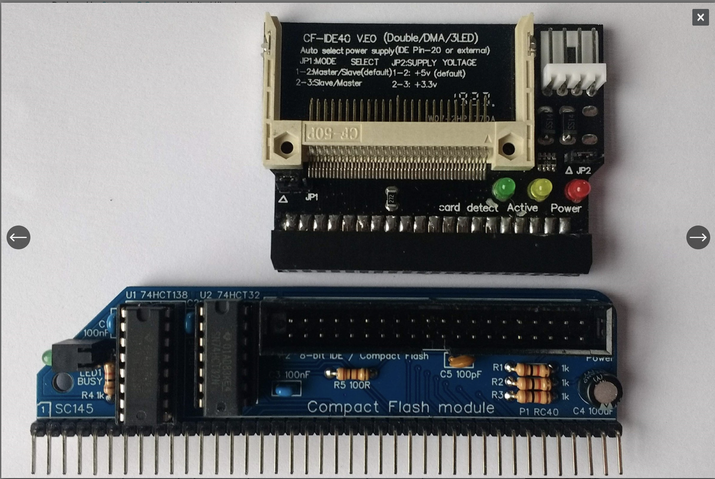
Thanks,
Norberto
--
You received this message because you are subscribed to the Google Groups "SEBHC" group.
To unsubscribe from this group and stop receiving emails from it, send an email to sebhc+un...@googlegroups.com.
To view this discussion on the web visit https://groups.google.com/d/msgid/sebhc/0d892778-0644-ff5d-3816-bb634958521b%40gmail.com.
Douglas Miller
Yes, one could do that and use the 40-pin header like before. I thought there was some advantage to eliminating the adapter, though. Maybe the new board could provide pads for the 40-pin IDE header as well as a CF-socket.
I thought I had heard talk about "bad adapters" before, or availability issues, or just clearance concerns. It really depends on what people want, though. I think my main point was that we don't need all that extra circuitry, be it 82C55 or "GIDE", between the bus signals and the CF card. As long as we aren't trying to support legacy IDE devices.
To view this discussion on the web visit https://groups.google.com/d/msgid/sebhc/A459586E-6AC0-4D0D-951A-9E98AFBDE862%40koyado.com.
norberto.collado koyado.com
To: se...@googlegroups.com <se...@googlegroups.com>
Subject: Re: [sebhc] H8-Dual-CF Controller for HDOS!
Yes, one could do that and use the 40-pin header like before. I thought there was some advantage to eliminating the adapter, though. Maybe the new board could provide pads for the 40-pin IDE header as well as a CF-socket.
Douglas Miller
If there are 4 CF sockets, we'll need a way to "select" between
master/slave pairs. That will be one (more) I/O port and at least
1-bit (flipflop) to contain the "select A" or "select B" signal.
If we are only using 0x88-0x8f for the CF cards, then we could use
anything in the (previously GIDE) range 0x80-0x87. To be safe, and
avoid software incompatibility, we could choose something that
GIDE did not use, like 0x80. We could choose to also permit access
to the GIDE registers at 0x86 and 0x87 by adding a CS1 connection.
Or have I missed something about the GIDE? From what I can tell, right now it can support only two drives since there is only one IDE channel.
To view this discussion on the web visit https://groups.google.com/d/msgid/sebhc/SN6PR01MB3855258A4A6DF7A4CC549D83F7F49%40SN6PR01MB3855.prod.exchangelabs.com.
Norberto Collado
I was thinking more in getting 4x masters as some CF cards will not play well as slave. So, slave is out to be able to use any CF card as master.
The new GIDE supports 4x CF cards. I will post the files online as it is ready to order some prototypes. I will find the ports being used or will be eventually used.
Thanks,
Norberto
To view this discussion on the web visit https://groups.google.com/d/msgid/sebhc/6c56997e-f94a-ae47-ccff-65b34f3a04bc%40gmail.com.
Douglas Miller
OK, so we'll need a "1 of 4" selector: two bits and a decoder, or
4 bits to direct-select. Basically, like what we did on the H8xSPI
adapter, adding "select" bits to add more devices.
[photo deleted]
To view this discussion on the web visit https://groups.google.com/d/msgid/sebhc/8EDF270E-659C-417A-9734-C05FC355ACF2%40koyado.com.
Richard Davis Jr.
To view this discussion on the web visit https://groups.google.com/d/msgid/sebhc/86d5ba44-4a5e-6274-609f-2d8e1bf3e333%40gmail.com.
Douglas Miller
It's no longer an IDE bus, but rather a set of CF cards that are
bused together. They would all be strapped for "drive 0" but we'd
have to use a separate I/O port to individually select the desired
CF card's CS0 line. Similar to what was done on legacy floppy
controllers or what is done on SPI buses.
To view this discussion on the web visit https://groups.google.com/d/msgid/sebhc/CABvWWgayh%2BHtWqZYiLdxi2sBM7NUv7fPKBt8rKQhiJf%2BwTR3gg%40mail.gmail.com.
Richard Davis Jr.
You received this message because you are subscribed to a topic in the Google Groups "SEBHC" group.
To unsubscribe from this topic, visit https://groups.google.com/d/topic/sebhc/imxfvMnNSvs/unsubscribe.
To unsubscribe from this group and all its topics, send an email to sebhc+un...@googlegroups.com.
To view this discussion on the web visit https://groups.google.com/d/msgid/sebhc/5f31a58f-ea6e-de0c-77ce-e233610b090d%40gmail.com.
Douglas Miller
Yes, except in this case we're talking about directly connecting
the CF cards to the H8 bus (more or less). CF cards are
essentially an I/O device themselves, with chip-select lines and
tri-state outputs, etc. They can be directly connected to the bus
the same way an INS8250 UART (or any other peripheral) chip would.
Since we're not doing DMA or any other special IDE features, we
don't need an IDE controller/bus. And since this is an 8-bit CPU
and bus, we don't need special circuitry to multiplex 16-bit data
(because CF cards support 8-bit mode).
To view this discussion on the web visit https://groups.google.com/d/msgid/sebhc/CABvWWgYVhbq-2fe%2B-qmwGhj%3DzdQP5VunM9e%3Di8vij4o3Pyz6Kw%40mail.gmail.com.
Richard Davis Jr.
To view this discussion on the web visit https://groups.google.com/d/msgid/sebhc/ca5af507-de52-083d-763c-1906c76f0aca%40gmail.com.
norberto.collado koyado.com
Sent: Thursday, April 21, 2022 5:00 PM
Douglas Miller
OK, may need to see more of the schematic but it looks like
essentially 2 IDE channels. So, if you have to run CF cards as
"master" (drive 0) then that's only two CF cards, right? You did
say there were issues when running a CF as a slave, right?
I guess one big question is, do we want to make this "direct CF" board software compatible with the GIDE? (can we accomplish that?) There may be some subtle differences, if someone were writing software that expected an IDE drive, but I think for existing software we can get pretty close.
Depending on the details for that GAL, we may want to re-use it
for the direct CF approach. It really depends on how we want to
support 4 CF cards (I'm wondering if it's really necessary to
support 4, or is 2 really (more than) enough?).
Yes it will less complicated than using the bit bang process.
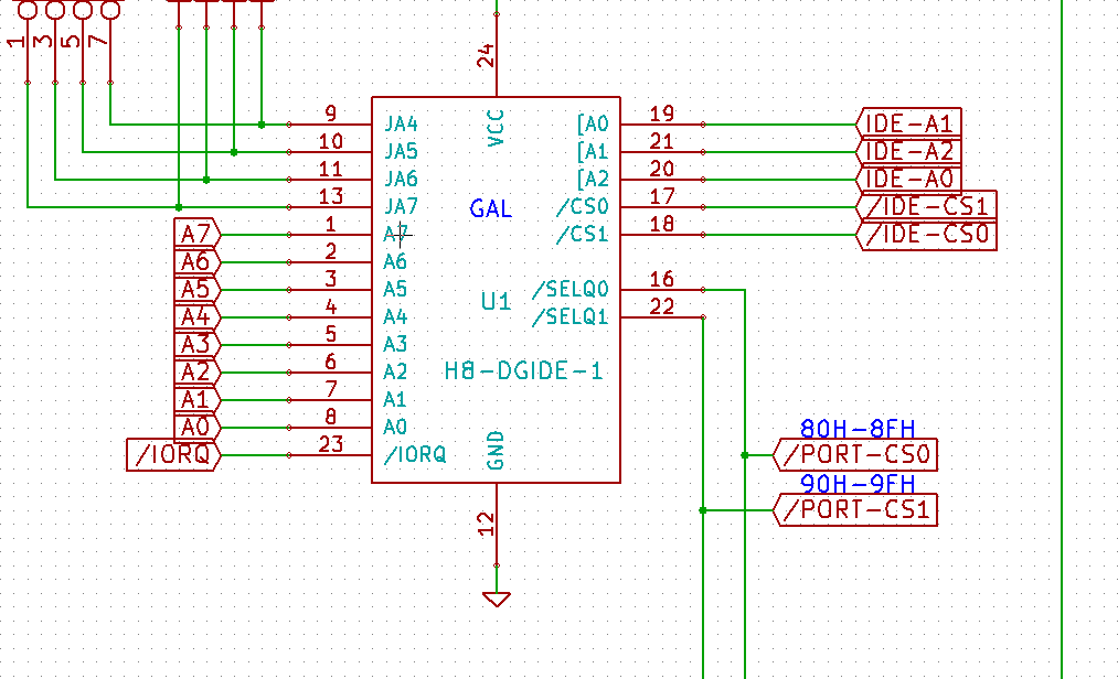
Douglas,
The new GIDE is using the following ports:
0x800x90
To view this discussion on the web visit https://groups.google.com/d/msgid/sebhc/SN6PR01MB3855FCF714A5CBC164253D78F7F79%40SN6PR01MB3855.prod.exchangelabs.com.
Norberto Collado
Two should be fine as masters. There is so much real state on this board, that I will need to figure out what else I could add if we go with two. I just want to wire this baby as in the RC2014 board, just direct wiring with slave disabled. The only GAL is for the I/O decoder.
Here is a better idea. Just wired two CF sockets and move the SD circuit from the NEW CP/Net controller and just leave the old CP/Net controller as it is. So, this board will have the 2 CF cards and the 2 SD cards for additional storage. I think this is more practical and provides better alternatives than floppies. A better, elegant, and simple design.
All four cards at the top and the logic below.
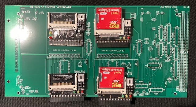

To view this discussion on the web visit https://groups.google.com/d/msgid/sebhc/a753dda0-4eaf-e5c7-f90a-e10a77eb5bc2%40gmail.com.
Norberto Collado
I will build out this controller and just add one of the CF connectors once I get them to test the timing on such controller. Rick is using I/O address 110Q for first master for HDOS. Let’s use this address to prototype one CF connector. Once is working/booting CP/M3 or even HDOS, then I will generate a new controller with 2x CF cards and 2X SPI SD cards for additional storage.
To view this discussion on the web visit https://groups.google.com/d/msgid/sebhc/2D2BCDA0-F6DD-44C4-8EE5-6366DF8FD20E%40koyado.com.
Douglas Miller
If we're going to go this route, combining SPI/SDC and CF, I'd
suggest using ports 0x80/0x81 (200Q/201Q) for the SPI logic, and
use the extra 2 bits in the SPI control register for the CF
select. Then keep the CF ports at 0x88-0x8f (210Q-217Q). The
previous GIDE logic used only ports 0x86-0x8f. Since this board
has completely different semantics than Rick's, I don't think it
makes sense to use port 110Q. The IDE/CF I/O semantics really
don't work well for cases where the base I/O address is not a
constant (since the 8080/Z80 does not have indexed I/O
instructions), so I'll resist the idea of having separate I/O
ranges for each CF card. It is possible, but it's messy plus we
don't have that many open I/O addresses on the H8 anymore.
How many people are currently using one of the GIDE boards? The ROM and CP/M 3 code does not support the second IDE channel (0x90-0x9f), so nothing there is expecting that. The GIDE code currently expects the second drive to be "slave", which supposedly does not work for CF cards so I would assume it's not being used. I'm trying to gauge whether anyone would be affected by a change is semantics for the second CF card.
To view this discussion on the web visit https://groups.google.com/d/msgid/sebhc/D9D4BD5E-5F8A-40D1-9E92-70DBB6CDCB48%40koyado.com.
Joseph Travis
To view this discussion on the web visit https://groups.google.com/d/msgid/sebhc/7572b401-b7ec-0747-1527-6e7b4cee189b%40gmail.com.
Dave McGuire
Fair enough. I'm only trying to make the point that, really, anyone
CAN actually do this. It should not be considered a barrier. I'm
willing to assist anyone who wants to learn how.
-Dave
Norberto Collado
I won’t say that! We are brainstorming what new features or updates it will need for the next version of such board. Also we need to build out this board to test the logic and timing to be correct. Afterwards move to the updates.
To view this discussion on the web visit https://groups.google.com/d/msgid/sebhc/CAGQDgBDgCkccmzzCTReJr5aK9HWS%3DLbMry0sPsOCp-bXPDexvg%40mail.gmail.com.
Joseph Travis
To view this discussion on the web visit https://groups.google.com/d/msgid/sebhc/1AA6F059-7999-4400-96C3-08B591FAA421%40koyado.com.
norberto...@koyado.com
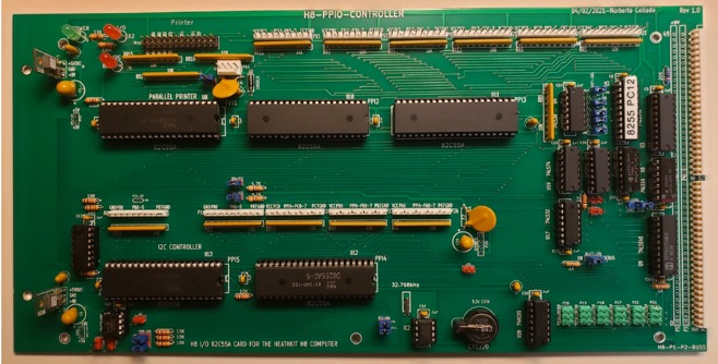
Also we have the 8255 I/O module as well designed by Terry S.
http://koyado.com/Heathkit/H8-82C55-PPIO.html

To view this discussion on the web visit https://groups.google.com/d/msgid/sebhc/CAGQDgBDaXNm8285-df-BVA-TAgfyqwmrYDapxdOA-MsRWXpZyg%40mail.gmail.com.
norberto...@koyado.com
After Rich verifies the H8-Dual-CF board is working fine, we can share one board with you as we have 3 left.
Norby
From: norberto...@koyado.com <norberto...@koyado.com>
Sent: Friday, April 22, 2022 1:13 PM
To: 'se...@googlegroups.com' <se...@googlegroups.com>
Subject: RE: [sebhc] H8-Dual-CF Controller for HDOS!
Also we have the 8255 I/O module as well designed by Terry S.
http://koyado.com/Heathkit/H8-82C55-PPIO.html
Sent: Friday, April 22, 2022 12:08 PM
To view this discussion on the web visit https://groups.google.com/d/msgid/sebhc/CAGQDgBDaXNm8285-df-BVA-TAgfyqwmrYDapxdOA-MsRWXpZyg%40mail.gmail.com.
norberto...@koyado.com
Douglas,
The 50 pin thru-hole CF connectors arrived today and they look great. I had to update to KiCad 5.0 as I had problem loading footprint with version 3, 4, and 6. Version 5 seems to be fine. With version 5, it cannot read my old schematics, so I cannot import.. ☹
I just started to play with V5 and it is easy to manage.
Here is me just playing with it (SD card adapter & 50 pin connectors)

Thanks,
Norberto
Douglas Miller
Looking good! I've got the simulator changes for the CF cards
done, and converted the new ROM gide boot over to CF. Just a
matter of doing the same conversion to the CP/M 3 drivers and I'll
have a bootable CP/M 3 image ready. You should be able to test on
a pretty simple CF card setup. Just need to do the I/O decoding
for /IOR and /IOW on ports 0x88-0x8f, and can hard-wire the /CS0
for testing purposes. Of course, there's probably no prototyping
board pattern that will fit the CF socket pins.
--
You received this message because you are subscribed to the Google Groups "SEBHC" group.
To unsubscribe from this group and stop receiving emails from it, send an email to sebhc+un...@googlegroups.com.
To view this discussion on the web visit https://groups.google.com/d/msgid/sebhc/007d01d85870%24fa2156e0%24ee6404a0%24%40koyado.com.