32K ROM?

smb...@gmail.com

norberto.collado koyado.com
Only the following boards will support the 32KB Monitor. As it is an EEPROM, we can download the FW thru the VDIP1 module.
- Z80 V4.x
- Z180 V5.x
- 8080A V1.x
It is described here: http://sebhc.durgadas.com/mms89/h8mon2/H8-Monitor-2.pdf
Douglas can give you more info if needed.
Norberto
--
You received this message because you are subscribed to the Google Groups "SEBHC" group.
To unsubscribe from this group and stop receiving emails from it, send an email to
sebhc+un...@googlegroups.com.
To view this discussion on the web visit
https://groups.google.com/d/msgid/sebhc/b2b304a3-ad5c-44aa-80df-104f4a1b9f18n%40googlegroups.com.
smb...@gmail.com
norberto.collado koyado.com
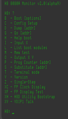
These are the extended COMMANDS menu on the H8 8080A board. You do not need to use the H8 Front Panel as everything can be done thru the serial port as in the H89.
To view this discussion on the web visit https://groups.google.com/d/msgid/sebhc/6b9d81b8-3803-4121-9886-fa65e342a7fdn%40googlegroups.com.

Glenn Roberts
On Jan 23, 2023, at 2:37 AM, norberto.collado koyado.com <norberto...@koyado.com> wrote:
These are the extended COMMANDS menu on the H8 8080A board. You do not need to use the H8 Front Panel as everything can be done thru the serial port as in the H89.

To view this discussion on the web visit https://groups.google.com/d/msgid/sebhc/SN6PR01MB3855C8DF124E9E809875DD71F7C89%40SN6PR01MB3855.prod.exchangelabs.com.

Douglas Miller
For the Z80 and Z180, I build a "n" (no FP) version of the ROMs, so you can use that in the case where the CPU is run without the FP. For some reason, I had concluded that the 8080A board could not run without the FP. But, in theory, the same thing could be done.
To view this discussion on the web visit https://groups.google.com/d/msgid/sebhc/F0AD7C40-1EC3-46A7-8624-5E866A31056D%40gmail.com.
Douglas Miller
I remembered why I did not build a "no FP" version of the 8080A
EEPROM. The 8080A board has no independent 2mS clock (or
single-step control), so I assumed it could not run without the
FP.
norberto.collado koyado.com
Do I need to add the H89 interrupt circuit to the 8080 board? We still have space in the prototype area.
Norberto
To view this discussion on the web visit https://groups.google.com/d/msgid/sebhc/37fc5d13-239e-b899-3d75-e83393ea63c4%40gmail.com.
Douglas Miller
I didn't see any 2mS clock on the 8080A schematic. Is there one? The "2mS clock enable" bit on port 362Q was not connected.
If there's no 2mS clock on the CPU board, we don't need port
363Q.
To view this discussion on the web visit https://groups.google.com/d/msgid/sebhc/SN6PR01MB38553210948D08ABC9C17C46F7C89%40SN6PR01MB3855.prod.exchangelabs.com.
norberto.collado koyado.com
Sent: Monday, January 23, 2023 7:40:35 AM
To: se...@googlegroups.com <se...@googlegroups.com>
Douglas Miller
So you did intend to make this board work without the front
panel?
To view this discussion on the web visit https://groups.google.com/d/msgid/sebhc/SN6PR01MB38559716329AFACBE4D0ABAAF7C99%40SN6PR01MB3855.prod.exchangelabs.com.
norberto.collado koyado.com
smb...@gmail.com
norberto.collado koyado.com
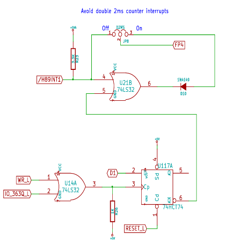
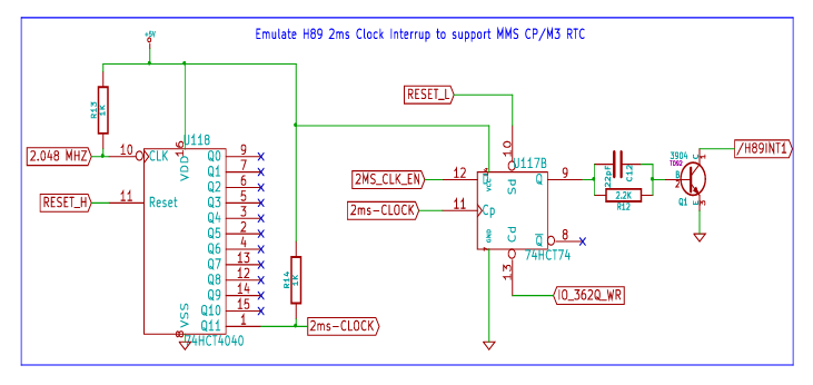
The H89 interrupt circuit was added to the board to make it behave as an H89 inside the H8 chassis and to boot MMS CP/M3 as the H89 did. CP/M3 was only supported on the H89 and not the H8 system. During initial tests it was found that the H8 was getting double interrupts, one from the front panel and one from the H89 circuit causing issues to the OS. To avoid the doble interrupt a flipflop, a gate, and a jumper was added when using the front panel.
Jumper position 2-3 = H8 front panel is generating the Interrupt or H89 is generating the interrupt under software control on port 363Q to boot MMS CP/M3. (NOT BOTH)
Jumper position 1-2 = H89 is generating the interrupt all the time as it is controlled by the HW on port 362Q.
In other words is like copying the H8 front panel interrupt circuit onto the CPU board, so that we can run the board without the front panel.
The circuit works fine with the old front panel or the new front panel.
Here is the second part of the circuit to understand better how this works.

From: se...@googlegroups.com <se...@googlegroups.com>
On Behalf Of smb...@gmail.com
Sent: Monday, January 23, 2023 10:29 PM
To: SEBHC <se...@googlegroups.com>
Subject: Re: [sebhc] 32K ROM?
Norberto, I wanted to ask more about the "avoid double 2ms counter interrupt" circuit above. Assuming the jumper is on positions 2-3, is the assumption that either the front panel is generating !INT1 or this circuit is generating !INT1, but not both at the same time? This is assuming an original front panel is used, not the new one that can utilize its own clock.
Scott

To view this discussion on the web visit https://groups.google.com/d/msgid/sebhc/de82ae16-51e0-4b51-b1fa-183598aa6fc1n%40googlegroups.com.