Gery's V4 Build Adventure

Gery Kissel

Terry Smedley
Terry Smedley
Gery Kissel
--
You received this message because you are subscribed to a topic in the Google Groups "SEBHC" group.
To unsubscribe from this topic, visit https://groups.google.com/d/topic/sebhc/WtApvdiP-cg/unsubscribe.
To unsubscribe from this group and all its topics, send an email to sebhc+un...@googlegroups.com.
To view this discussion on the web visit https://groups.google.com/d/msgid/sebhc/64348cb1-6ceb-4478-930f-050dd2743e71n%40googlegroups.com.

Glenn Roberts
On Jun 14, 2021, at 7:19 PM, Terry Smedley <terry....@gmail.com> wrote:
Looking good, Geri.
--
You received this message because you are subscribed to the Google Groups "SEBHC" group.
To unsubscribe from this group and stop receiving emails from it, send an email to sebhc+un...@googlegroups.com.
To view this discussion on the web visit https://groups.google.com/d/msgid/sebhc/9f9e5688-90bf-4a7c-9c3e-eb3d3750418dn%40googlegroups.com.
Gery Kissel
You received this message because you are subscribed to a topic in the Google Groups "SEBHC" group.
To unsubscribe from this topic, visit https://groups.google.com/d/topic/sebhc/WtApvdiP-cg/unsubscribe.
To unsubscribe from this group and all its topics, send an email to sebhc+un...@googlegroups.com.
To view this discussion on the web visit https://groups.google.com/d/msgid/sebhc/7D12B033-59D4-4D1B-963A-0F5CF504FE1E%40gmail.com.
terry.smedley
To unsubscribe from this topic, visit https://groups.google.com/d/topic/sebhc/WtApvdiP-cg/unsubscribe.
To unsubscribe from this group and all its topics, send an email to sebhc+un...@googlegroups.com.
To view this discussion on the web visit https://groups.google.com/d/msgid/sebhc/7D12B033-59D4-4D1B-963A-0F5CF504FE1E%40gmail.com.

Douglas Miller
That's my approach, too. Except that since I would have recently picked up the soldering iron by the wrong end, my finger is relatively numb to any additional pain.
To view this discussion on the web visit https://groups.google.com/d/msgid/sebhc/60c7efa2.1c69fb81.c5027.a875%40mx.google.com.

George Farris
Gery Kissel
terry.smedley
You received this message because you are subscribed to a topic in the Google Groups "SEBHC" group.
To unsubscribe from this topic, visit https://groups.google.com/d/topic/sebhc/WtApvdiP-cg/unsubscribe.
To unsubscribe from this group and all its topics, send an email to sebhc+un...@googlegroups.com.
Gery Kissel
To view this discussion on the web visit https://groups.google.com/d/msgid/sebhc/60ca7b21.1c69fb81.c551b.a17f%40mx.google.com.

norberto...@koyado.com
On decoupling caps, for 74xx it is recommended one 0.01uf or 0.1uf cap for every IC as close as possible to the VCC pin and with GND connected thru a via to the ground plane. Older recommendations was to use “one” 0.01uf or 0.1uf capacitor for every 2 to 3 IC’s. I do try to use one decoupling cap per IC, but sometimes IC positioning is hard to do as we add more functionality to the board, so I default to the older recommendations.
If you look at the original H8 front panel board, all decoupling caps are on the 5V/GND voltage rails. Not even one cap is closed to the IC VCC/GND pins. The H8 front panel board is working fine, even the decoupling caps being a mile away from each IC.
Why I’m using 0.1uf decoupling caps? The specs for the memory IC’s recommends to use a 0.1uf per IC. So this is my standard now.
For analog IC’s or Oscillators, I used an inductor or ferrite bead along with a 10uf + 01uf cap to provide additional filtering in noisy digital environment. You will see such this on the H37/H67/H17 controllers that I designed. On the H8-SSI I used them to protect the Music circuit, APU, and Analog voltage decoder. On the H8 SSI music circuit, I used them as “mixed-signal” between AGND and GND ground pins to avoid using two dedicated linear regulators for such circuit. In other cases I used it as a suppressing noise at the source. So you will see combinations of all these methods.
Gery,
How many caps do you need and values?
Thanks,
Norberto
From: se...@googlegroups.com <se...@googlegroups.com> On Behalf Of terry.smedley
Sent: Wednesday, June 16, 2021 3:29 PM
To: se...@googlegroups.com
Subject: Re: [sebhc] Re: Gery's V4 Build Adventure
Hi Gery:
I would not be surprised at a small count discrepancy in the 0.1uf count. If your count is 37+7, I will update the BOM.
Norberto is generous with caps (not a criticism). Some designers use far fewer than 1:1. You will not have any trouble with a few missing caps, certainly not in the short term, and especially if the missing ones aren't all in one area. Others can share their take.
Terry
Sent from my Verizon, Samsung Galaxy smartphone
-------- Original message --------
From: Gery Kissel <gkisselsp...@gmail.com>
Date: 6/16/21 1:47 PM (GMT-08:00)
To: SEBHC <se...@googlegroups.com>
Subject: Re: [sebhc] Re: Gery's V4 Build Adventure
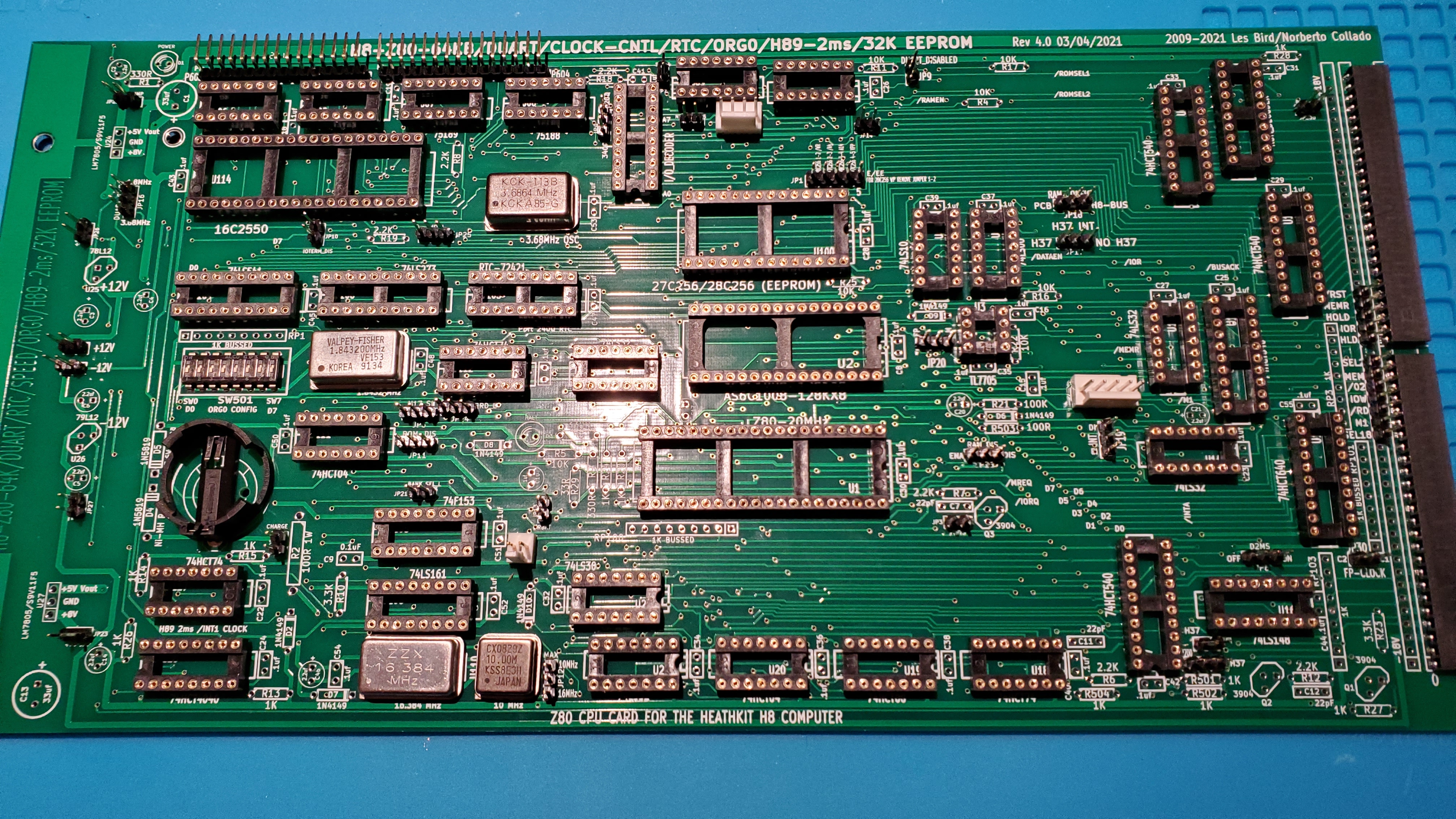
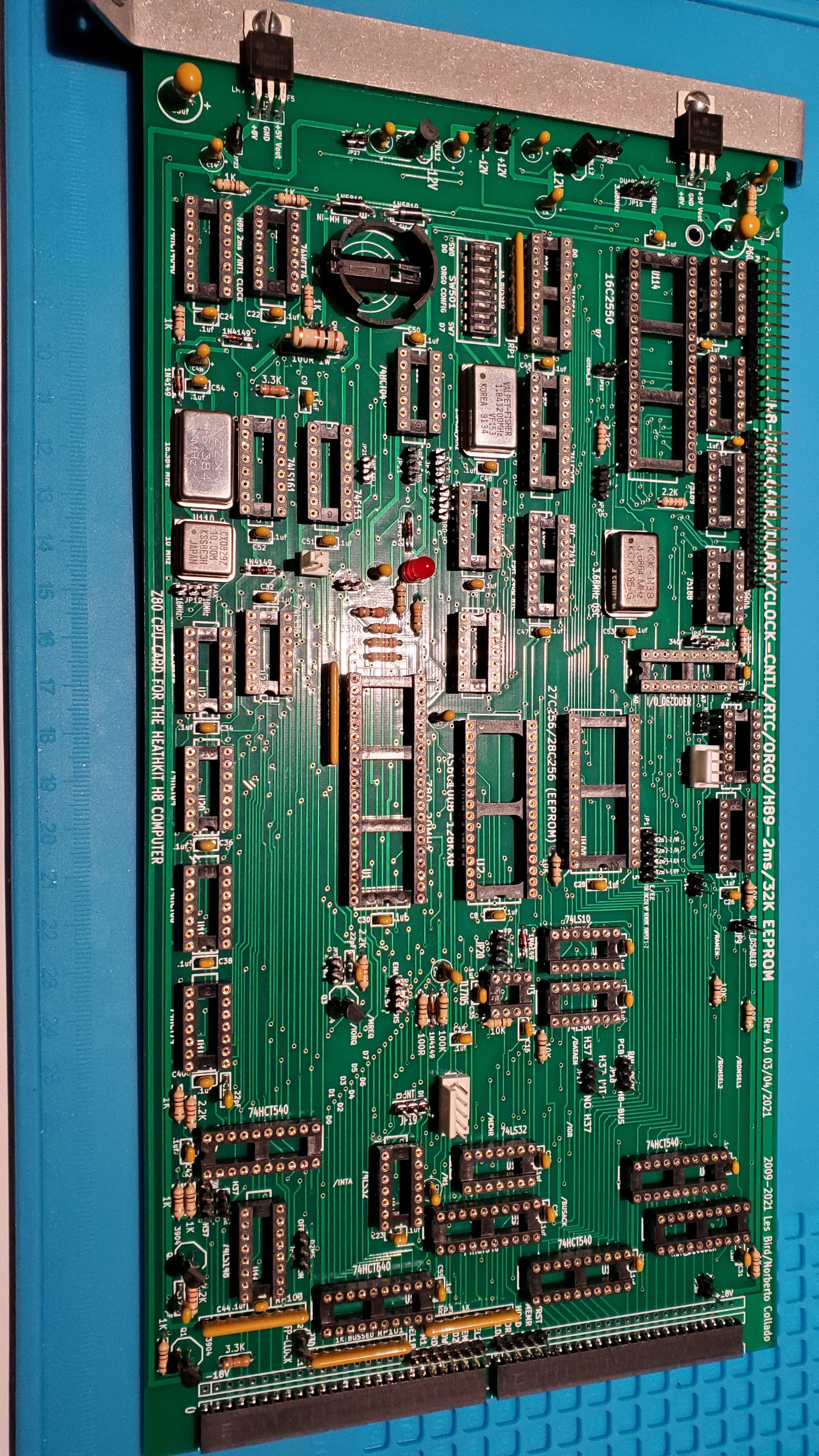
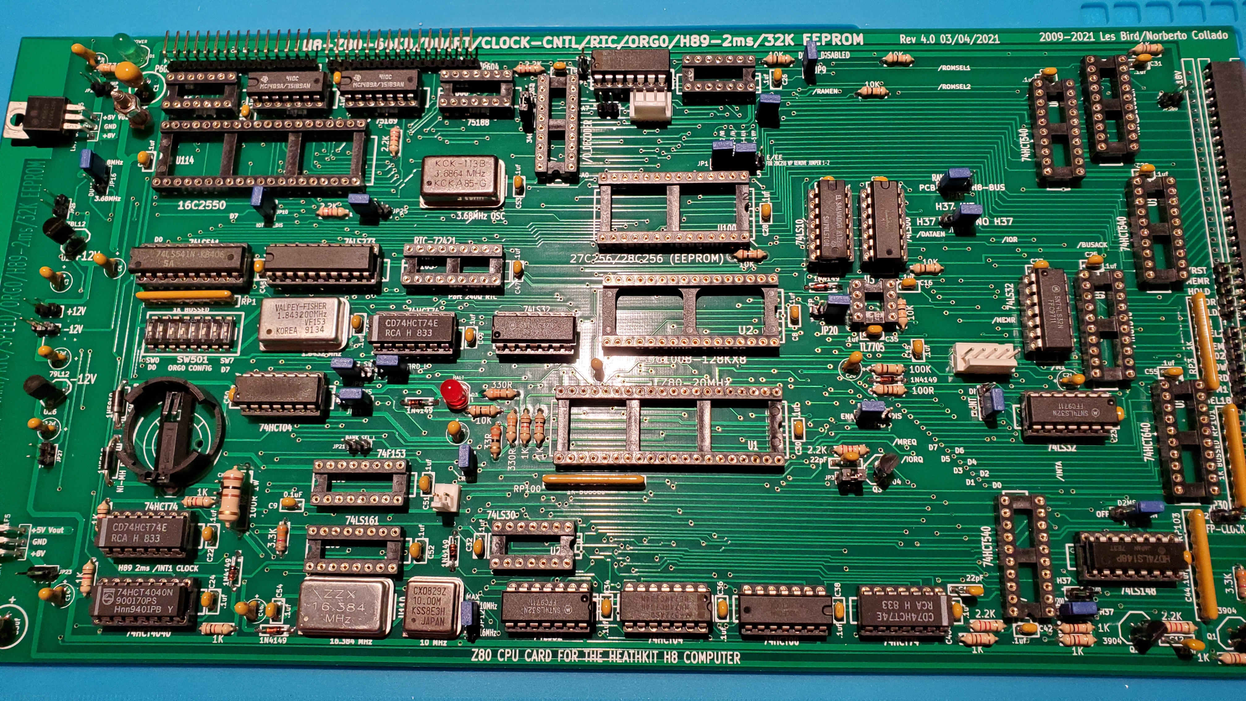
Build session 7 is done. See photo below.
Resistor networks, LEDs and decoupling caps installed.
BOM question on decoupling caps. The BOM states that each IC has a decoupling cap. I see 4 that do not.
Am I missing something?
Also the BOM states 39 caps and suggests ordering a bag of 100. I tried to do that but the bag part number was not available so I ordered 40 caps.
I have installed 37 caps and would like confirmation that is the correct number. I count 7 for the DUART board. Total of 44.
Gonna be short a few caps.
Gery
On Monday, June 14, 2021 at 9:09:53 PM UTC-4 frg wrote:
I used to say to my associates at work, "It's a poor mind that can only find one way to spell a word!"
George
On Mon, 2021-06-14 at 19:37 -0400, Gery Kissel wrote:
No worries. You are in great company. My favorite aunt used to address cards to me spelled that way. No spell correction excuse for her. I never did figure out why she did that.
Gery
On Mon, Jun 14, 2021, 7:21 PM Terry Smedley <terry....@gmail.com> wrote:
I am going to have to change my dictionary, Gery!
Apologies again
On Monday, June 14, 2021 at 1:24:19 PM UTC-7 gkisselsp...@gmail.com wrote:
I thought I would start a thread about my V4 build. Hopefully some will find it interesting and maybe encouraging.
Please feel free to comment and lend advice if you see anything astray.
We pick up our story at the end of session 5. Each session has been between 45 minutes and an hour and 20 minutes.
At the end of 5, all the sockets, connectors and jumpers are on. The only parts on the board at the moment that purposely modify the flow of electrons are the oscillators.
I installed ALL the jumper locations as well as a few extra near the header connectors.
I do not plan to have use for all of the jumpers but I did not want to suffer later from jumper envy.
I learned that my cushy engineering career has allowed my calloused finger tips to heal. Getting a few of those 2 pin jumpers perfect was painful.
I did notice that the jumpers I installed near the headers fit firm. I vote that future jumper holes have similar spacing. But that may be violating some PCB footprint rule.
Anyway, my next step is to install the less "bendy" leaded components. Resistor networks etc. Then tantalum / electrolytic caps, resistors and decoupling caps.
The old school regulators will be last so I can make sure they fit up to the mounting bracket.
I will power up the board on the bench without any ICs in place to make sure I have not made any costly mistakes.
Stay tuned if interested.
Gery
--
You received this message because you are subscribed to a topic in the Google Groups "SEBHC" group.
To unsubscribe from this topic, visit https://groups.google.com/d/topic/sebhc/WtApvdiP-cg/unsubscribe.
To unsubscribe from this group and all its topics, send an email to sebhc+un...@googlegroups.com.
To view this discussion on the web visit https://groups.google.com/d/msgid/sebhc/f182fa0a-7de6-4a62-8680-a7995aa7acd5n%40googlegroups.com.
--
You received this message because you are subscribed to the Google Groups "SEBHC" group.
To unsubscribe from this group and stop receiving emails from it, send an email to sebhc+un...@googlegroups.com.
To view this discussion on the web visit https://groups.google.com/d/msgid/sebhc/60ca7b21.1c69fb81.c551b.a17f%40mx.google.com.
glenn.f...@gmail.com
Congratulations Gery. Steady progress!
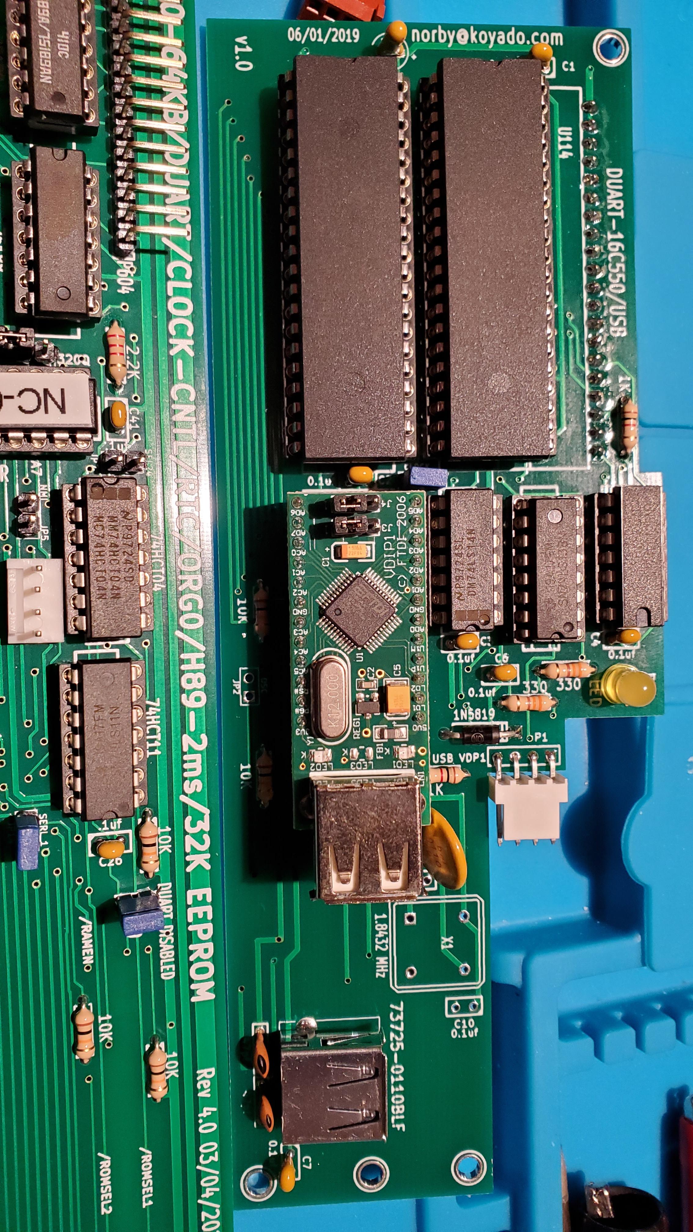
I did encounter a glitch with my new setup. For some reason CP/M 3 would not boot properly. It would stop after printing “59K TPA” and never run the command processor. HDOS and CP/M 2.2.04 were booting and running fine. Through a series of swapping out components I determined that the problem was the second 16C550 UART chip (U602) on the DUART board. I haven’t looked at the schematic but that’s not even the one that services the console is it? I don’t even have anything connected to the second serial port. anyway, upon replacing that UART all is well!
I am currently attempting to establish my working environment under the new 4.0 board. My current thinking is to move VPIP over (probably via floppy drive) and then use VPIP and a USB stick to transfer the files I need.
On Monday, June 14, 2021 at 9:09:53 PM UTC-4 frg wrote:
I used to say to my associates at work, "It's a poor mind that can only find one way to spell a word!"
George
On Mon, 2021-06-14 at 19:37 -0400, Gery Kissel wrote:
No worries. You are in great company. My favorite aunt used to address cards to me spelled that way. No spell correction excuse for her. I never did figure out why she did that.
Gery
On Mon, Jun 14, 2021, 7:21 PM Terry Smedley <terry....@gmail.com> wrote:
I am going to have to change my dictionary, Gery!
Apologies again
On Monday, June 14, 2021 at 1:24:19 PM UTC-7 gkisselsp...@gmail.com wrote:
I thought I would start a thread about my V4 build. Hopefully some will find it interesting and maybe encouraging.
Please feel free to comment and lend advice if you see anything astray.
We pick up our story at the end of session 5. Each session has been between 45 minutes and an hour and 20 minutes.
At the end of 5, all the sockets, connectors and jumpers are on. The only parts on the board at the moment that purposely modify the flow of electrons are the oscillators.
I installed ALL the jumper locations as well as a few extra near the header connectors.
I do not plan to have use for all of the jumpers but I did not want to suffer later from jumper envy.
I learned that my cushy engineering career has allowed my calloused finger tips to heal. Getting a few of those 2 pin jumpers perfect was painful.
I did notice that the jumpers I installed near the headers fit firm. I vote that future jumper holes have similar spacing. But that may be violating some PCB footprint rule.
Anyway, my next step is to install the less "bendy" leaded components. Resistor networks etc. Then tantalum / electrolytic caps, resistors and decoupling caps.
The old school regulators will be last so I can make sure they fit up to the mounting bracket.
I will power up the board on the bench without any ICs in place to make sure I have not made any costly mistakes.
Stay tuned if interested.
Gery
--
You received this message because you are subscribed to a topic in the Google Groups "SEBHC" group.
To unsubscribe from this topic, visit https://groups.google.com/d/topic/sebhc/WtApvdiP-cg/unsubscribe.
To unsubscribe from this group and all its topics, send an email to sebhc+un...@googlegroups.com.
To view this discussion on the web visit https://groups.google.com/d/msgid/sebhc/f182fa0a-7de6-4a62-8680-a7995aa7acd5n%40googlegroups.com.
--
You received this message because you are subscribed to a topic in the Google Groups "SEBHC" group.
To unsubscribe from this topic, visit https://groups.google.com/d/topic/sebhc/WtApvdiP-cg/unsubscribe.
To unsubscribe from this group and all its topics, send an email to sebhc+un...@googlegroups.com.
To view this discussion on the web visit https://groups.google.com/d/msgid/sebhc/60ca7b21.1c69fb81.c551b.a17f%40mx.google.com.
--
You received this message because you are subscribed to the Google Groups "SEBHC" group.
To unsubscribe from this group and stop receiving emails from it, send an email to sebhc+un...@googlegroups.com.
To view this discussion on the web visit https://groups.google.com/d/msgid/sebhc/CAK6523sGoHKK0QUsatZ81RMmwxRumE_-uL1219TSZNuUwQMzmg%40mail.gmail.com.
Gery Kissel
Glenn Roberts
On Jun 18, 2021, at 5:32 PM, Gery Kissel <gkisselsp...@gmail.com> wrote:
Resistance if futile!
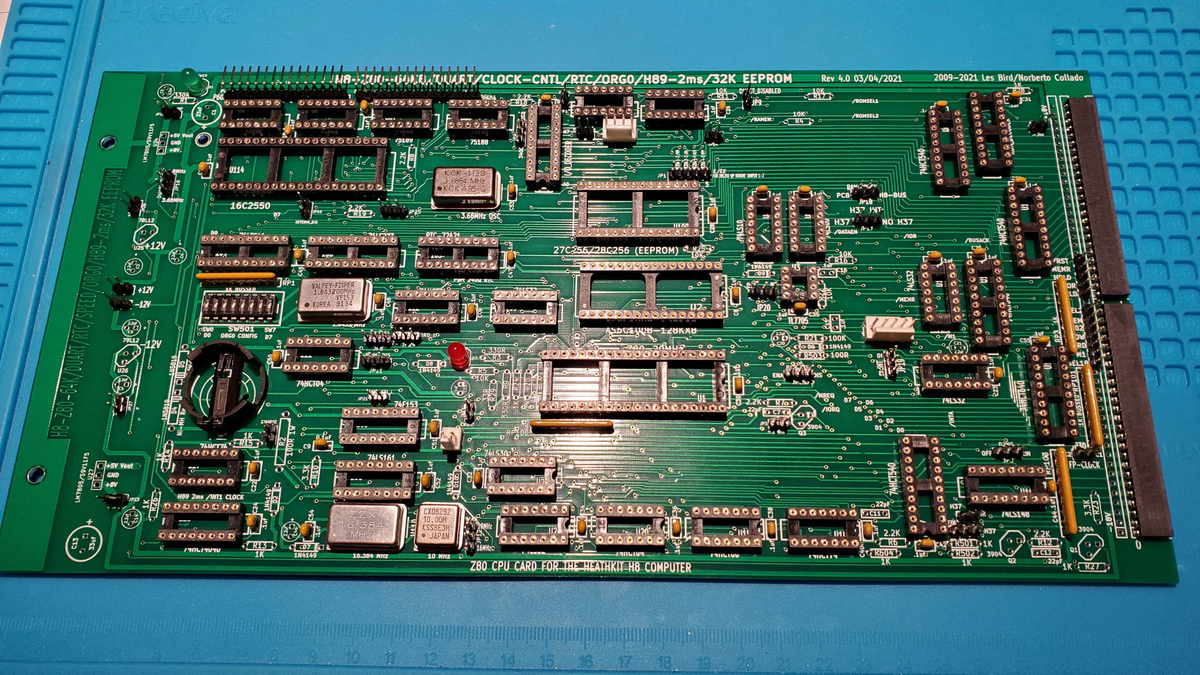
Build session 8 is done. Everything is on the V4 board except the resistors and 4 voltage regulators.To be clear to the group, the bypass cap count on the V4 is 39. The BOM is accurate.ANDThe bypass caps for the DUART are also on the BOM and correct.Multiple errors on my part! AND I have all the caps I need. It turns out for some unknown reason I bought the caps for the V4 from Mouser and the DUART from Jameco.Happy Father's to my fellow dads out there!Gery
To view this discussion on the web visit https://groups.google.com/d/msgid/sebhc/939c2e29-c6a6-4c4d-a060-db995ca7ff4en%40googlegroups.com.
<Session 8.jpg>
Gery Kissel
norberto.collado koyado.com
Sent: Friday, June 18, 2021 4:17 PM
To: SEBHC <se...@googlegroups.com>
Subject: Re: [sebhc] Gery's V4 Build Adventure
Gery Kissel
Terry Smedley
--
You received this message because you are subscribed to a topic in the Google Groups "SEBHC" group.
To unsubscribe from this topic, visit https://groups.google.com/d/topic/sebhc/WtApvdiP-cg/unsubscribe.
To unsubscribe from this group and all its topics, send an email to sebhc+un...@googlegroups.com.
To view this discussion on the web visit https://groups.google.com/d/msgid/sebhc/49bfbe7e-8f56-46a5-8814-ff50de81a1bfn%40googlegroups.com.
norberto...@koyado.com
Almost there!
Norby
From: se...@googlegroups.com <se...@googlegroups.com> On Behalf Of Gery Kissel
Sent: Sunday, June 20, 2021 12:57 PM
To: SEBHC <se...@googlegroups.com>
Subject: Re: [sebhc] Gery's V4 Build Adventure
It's Father's Day and boy am I stuffed!
--
You received this message because you are subscribed to the Google Groups "SEBHC" group.
To unsubscribe from this group and stop receiving emails from it, send an email to sebhc+un...@googlegroups.com.
To view this discussion on the web visit https://groups.google.com/d/msgid/sebhc/49bfbe7e-8f56-46a5-8814-ff50de81a1bfn%40googlegroups.com.
Gery Kissel
Gery Kissel

glenn.f...@gmail.com
There seems to be an endless array of space shuttles that Lego has come up with over the years. I built 8480 way back when I coached a Mindstorms team. It was a pretty cool kit. Lots of motors. Enjoy!
From: se...@googlegroups.com <se...@googlegroups.com> On Behalf Of Gery Kissel
Sent: Sunday, June 20, 2021 7:25 PM
To: SEBHC <se...@googlegroups.com>
Subject: Re: [sebhc] Gery's V4 Build Adventure
Sensing the end of my "ancient computer" project, my family has already lined up my next project.
On Sunday, June 20, 2021 at 7:20:47 PM UTC-4 Gery Kissel wrote:
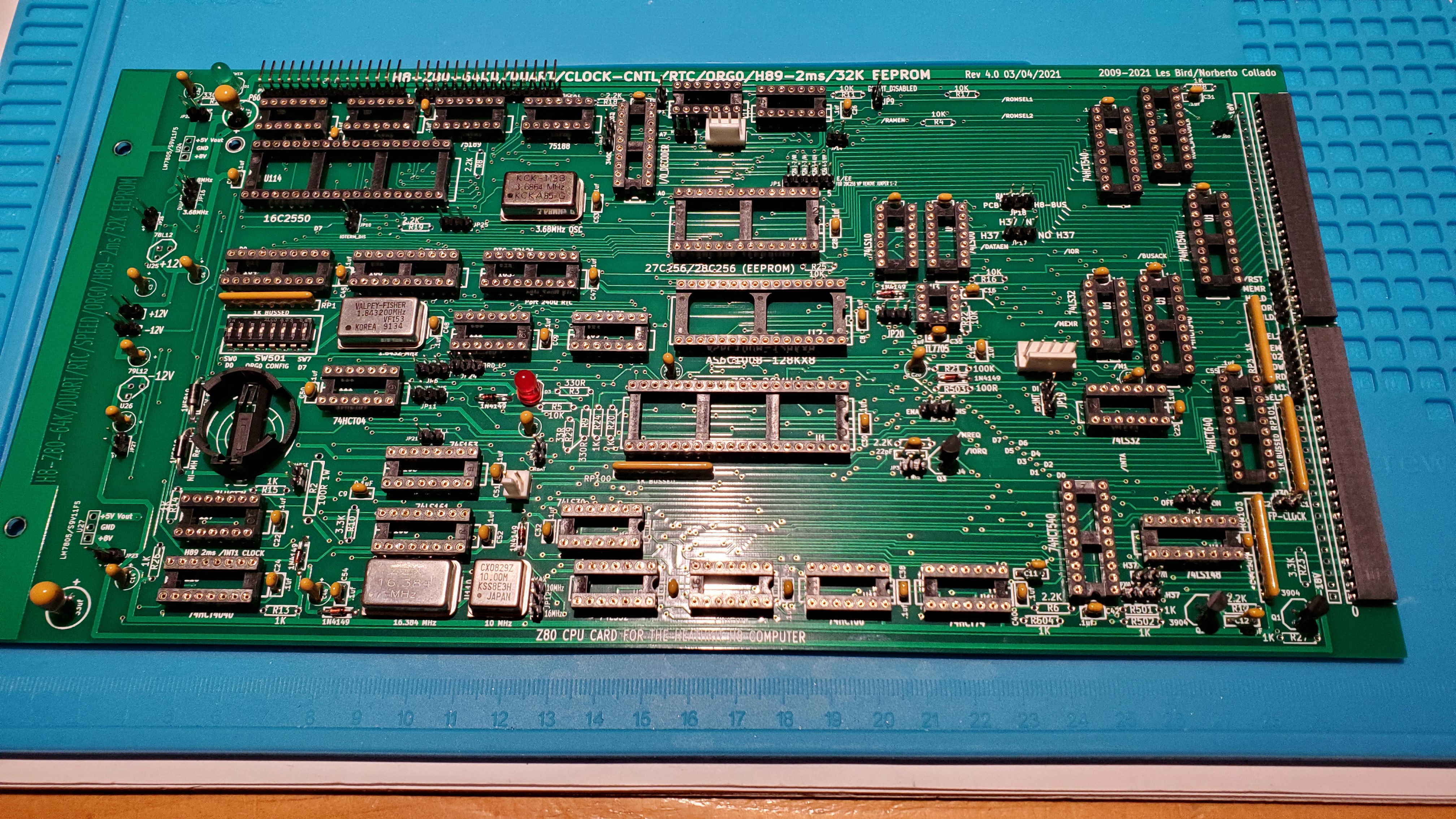
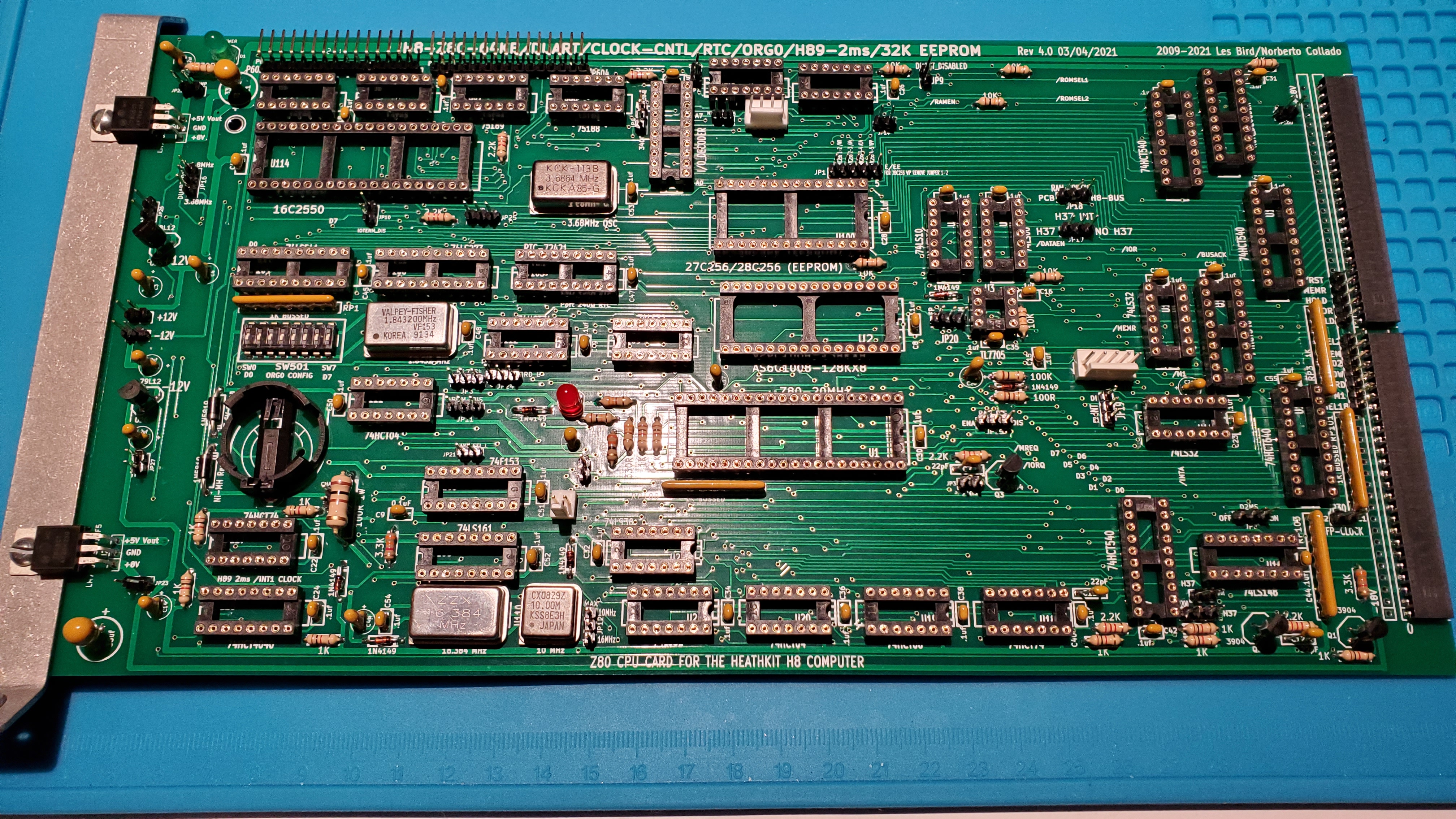
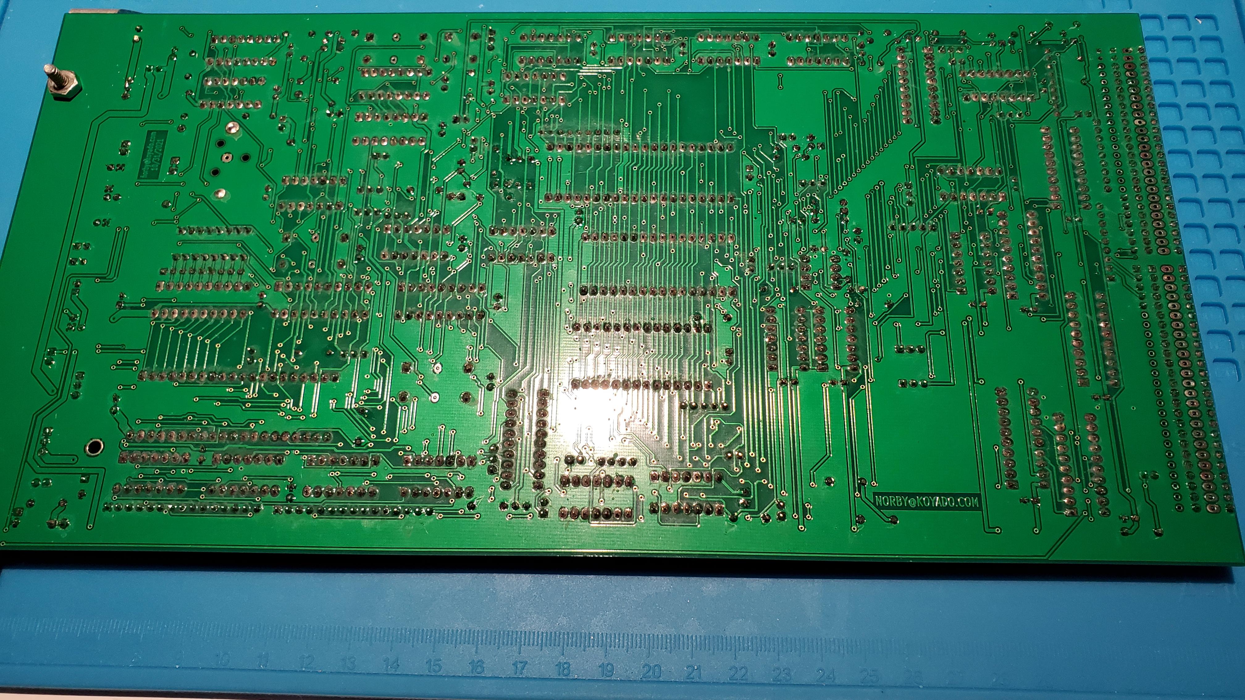
Just for fun, here is a shot of the "prickly" side of the board.
Not as pretty, but certainly where all the work gets done.
--
You received this message because you are subscribed to the Google Groups "SEBHC" group.
To unsubscribe from this group and stop receiving emails from it, send an email to sebhc+un...@googlegroups.com.
To view this discussion on the web visit https://groups.google.com/d/msgid/sebhc/fbca606c-d6ed-43b9-8e7b-54f6726bd7f5n%40googlegroups.com.
Norberto Collado
Please double check for any solder shorts or pins missing solder. Reflow any shinny area.
Thanks,
Norby
From: "se...@googlegroups.com" <se...@googlegroups.com> on behalf of Gery Kissel <gkisselsp...@gmail.com>
Reply-To: "se...@googlegroups.com" <se...@googlegroups.com>
Date: Sunday, June 20, 2021 at 4:20 PM
To: "se...@googlegroups.com" <se...@googlegroups.com>
Subject: Re: [sebhc] Gery's V4 Build Adventure
Just for fun, here is a shot of the "prickly" side of the board.
Not as pretty, but certainly where all the work gets done.

--
You received this message because you are subscribed to the Google Groups "SEBHC" group.
To unsubscribe from this group and stop receiving emails from it, send an email to sebhc+un...@googlegroups.com.
To view this discussion on the web visit https://groups.google.com/d/msgid/sebhc/4875b51d-658b-4600-8748-9a7715af9975n%40googlegroups.com.
norberto...@koyado.com
Gery,
The 78L12 and 79L12 regulators are backwards. The flat section of the body must match the flat area of the symbol. Here is a picture of Glenn’s regulator vs yours. If they are backwards they will blow-up or burn out.

Thanks
Norberto
From: se...@googlegroups.com <se...@googlegroups.com> On Behalf Of Gery Kissel
Sent: Sunday, June 20, 2021 12:57 PM
To: SEBHC <se...@googlegroups.com>
Subject: Re: [sebhc] Gery's V4 Build Adventure
It's Father's Day and boy am I stuffed!

--
You received this message because you are subscribed to the Google Groups "SEBHC" group.
To unsubscribe from this group and stop receiving emails from it, send an email to sebhc+un...@googlegroups.com.
To view this discussion on the web visit https://groups.google.com/d/msgid/sebhc/49bfbe7e-8f56-46a5-8814-ff50de81a1bfn%40googlegroups.com.
terry.smedley
To unsubscribe from this topic, visit https://groups.google.com/d/topic/sebhc/WtApvdiP-cg/unsubscribe.
To unsubscribe from this group and all its topics, send an email to sebhc+un...@googlegroups.com.
To view this discussion on the web visit https://groups.google.com/d/msgid/sebhc/008b01d76668%2493469f70%24b9d3de50%24%40koyado.com.
Gery Kissel
You received this message because you are subscribed to a topic in the Google Groups "SEBHC" group.
To unsubscribe from this topic, visit https://groups.google.com/d/topic/sebhc/WtApvdiP-cg/unsubscribe.
To unsubscribe from this group and all its topics, send an email to sebhc+un...@googlegroups.com.
To view this discussion on the web visit https://groups.google.com/d/msgid/sebhc/008b01d76668%2493469f70%24b9d3de50%24%40koyado.com.
Gery Kissel
norberto...@koyado.com
Glad that you shared such photo to avoid burning out the 12v regulators. 😊
From: se...@googlegroups.com <se...@googlegroups.com> On Behalf Of Gery Kissel
Sent: Monday, June 21, 2021 12:49 PM
To: SEBHC <se...@googlegroups.com>
Subject: Re: [sebhc] Gery's V4 Build Adventure
Green light!
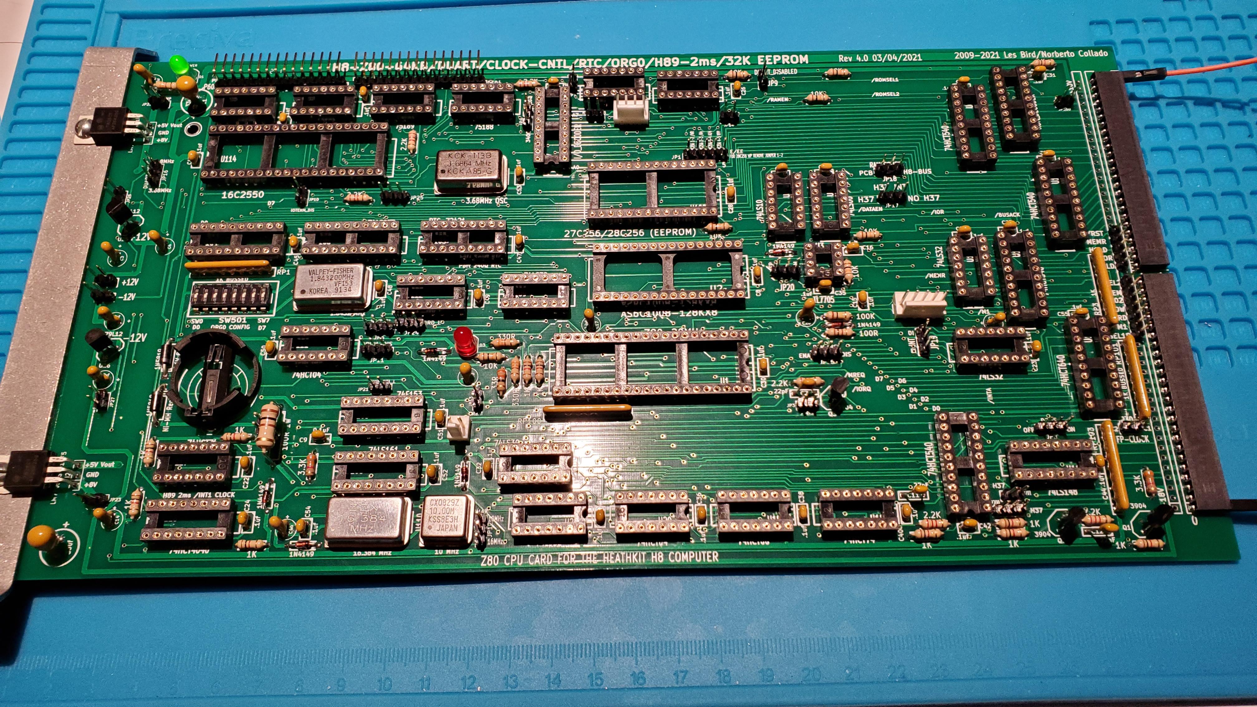
Thanks again to Norberto and Terry for catching my TO92 case orientation screw up. I guess I am going to have to re take the master builder test!
I got everything switched around correctly and applied power.
Supplies all working correctly. Did a general sanity check for 5V around the board.
I hopefully will get to starting the DUART board tomorrow.

On Monday, June 21, 2021 at 6:20:48 AM UTC-4 Gery Kissel wrote:
Wow. Thanks for catching that! Total brain fart on my part.
At least I am consistent. Both regulators and 3 transistors are in wrong.
On Mon, Jun 21, 2021, 2:42 AM <norberto...@koyado.com> wrote:
Gery,
The 78L12 and 79L12 regulators are backwards. The flat section of the body must match the flat area of the symbol. Here is a picture of Glenn’s regulator vs yours. If they are backwards they will blow-up or burn out.
Thanks
Norberto
From: se...@googlegroups.com <se...@googlegroups.com> On Behalf Of Gery Kissel
Sent: Sunday, June 20, 2021 12:57 PM
To: SEBHC <se...@googlegroups.com>
Subject: Re: [sebhc] Gery's V4 Build Adventure
It's Father's Day and boy am I stuffed!
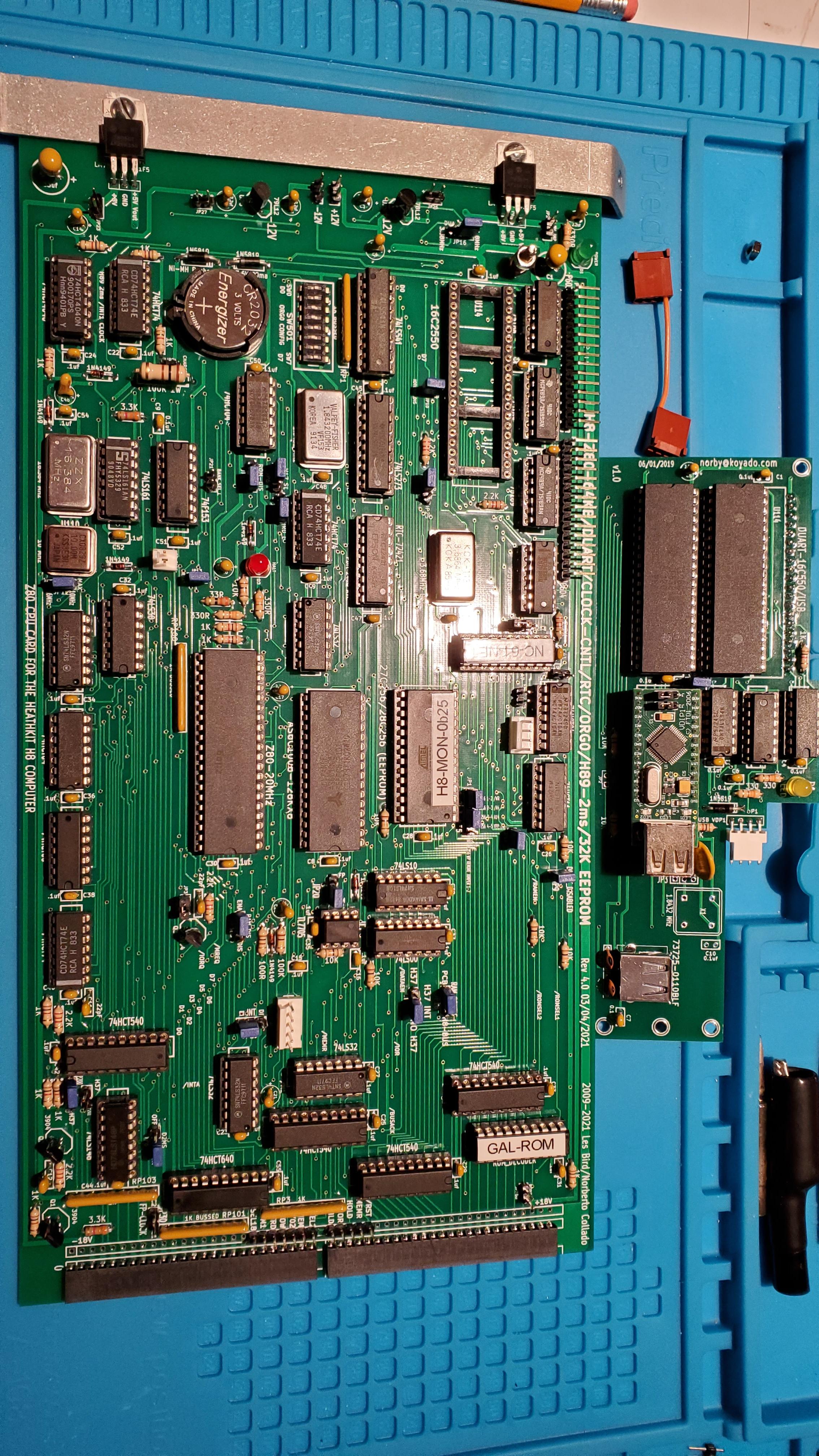
Finished soldering components on the V4 board this afternoon.
Next steps:
Remove mounting bracket which was used at this point to locate the regulators.
Hook up the bench power supply and do some basic power checks.
Build the DUART board this week and check power.
Install ICs, jumpers, DUART board and mounting bracket.
Finish!
--
You received this message because you are subscribed to the Google Groups "SEBHC" group.
To unsubscribe from this group and stop receiving emails from it, send an email to sebhc+un...@googlegroups.com.
To view this discussion on the web visit https://groups.google.com/d/msgid/sebhc/49bfbe7e-8f56-46a5-8814-ff50de81a1bfn%40googlegroups.com.
--
You received this message because you are subscribed to a topic in the Google Groups "SEBHC" group.
To unsubscribe from this topic, visit https://groups.google.com/d/topic/sebhc/WtApvdiP-cg/unsubscribe.
To unsubscribe from this group and all its topics, send an email to sebhc+un...@googlegroups.com.
To view this discussion on the web visit https://groups.google.com/d/msgid/sebhc/008b01d76668%2493469f70%24b9d3de50%24%40koyado.com.
--
You received this message because you are subscribed to the Google Groups "SEBHC" group.
To unsubscribe from this group and stop receiving emails from it, send an email to sebhc+un...@googlegroups.com.
To view this discussion on the web visit https://groups.google.com/d/msgid/sebhc/f8688b59-402a-4304-879d-3d4584f6b463n%40googlegroups.com.
Gery Kissel
To view this discussion on the web visit https://groups.google.com/d/msgid/sebhc/010301d76728%243fca1500%24bf5e3f00%24%40koyado.com.
Gery Kissel
glenn.f...@gmail.com
Here are the connectors I used
Measuring with my micrometer the pins with the cylindrical shoulder ring appear to be .64mm (.025”) in diameter; the longer pins are .46 mm (.018”) in diameter. The ones with the shoulder are soldered into the PC board; the longer narrower pins plug into the 40-pin socket on the CPU board. The shouldered pin length is 4.3mm (.17”); the narrower pin length is 4.75mm (.186”).
I recall having trouble finding the right part here. Norberto recommended this part
https://groups.google.com/g/sebhc/c/WZmRSwGvLNM/m/7dMmbavuAQAJ
I think this is more of the discussion:
https://groups.google.com/g/sebhc/c/SRP5OUD9Jec/m/bzUv0lQXFQAJ
sorry, since I had bought these parts a while ago I didn’t think to mention this. At a glance I didn’t see any part spec’ed for this in the BOM? But perhaps we should update that?
Looking at the Mouser data sheet
it looks like the correct part would end in “-A” but you bought “-A-1”?, though that part appears to have different pin lengths than the one I used.
I believe you should be able to test your board by simply plugging in the 16C550 UART in the 40-pin receptacle on the CPU board (and possibly changing some jumpers, e.g. disabling the second com port and/or VDIP1?). that would let you test things if you have to wait for more parts…
- Glenn
From: se...@googlegroups.com <se...@googlegroups.com> On Behalf Of Gery Kissel
Sent: Tuesday, June 22, 2021 4:03 PM
To: SEBHC <se...@googlegroups.com>
Subject: Re: [sebhc] Gery's V4 Build Adventure
A little advice from the experts please....
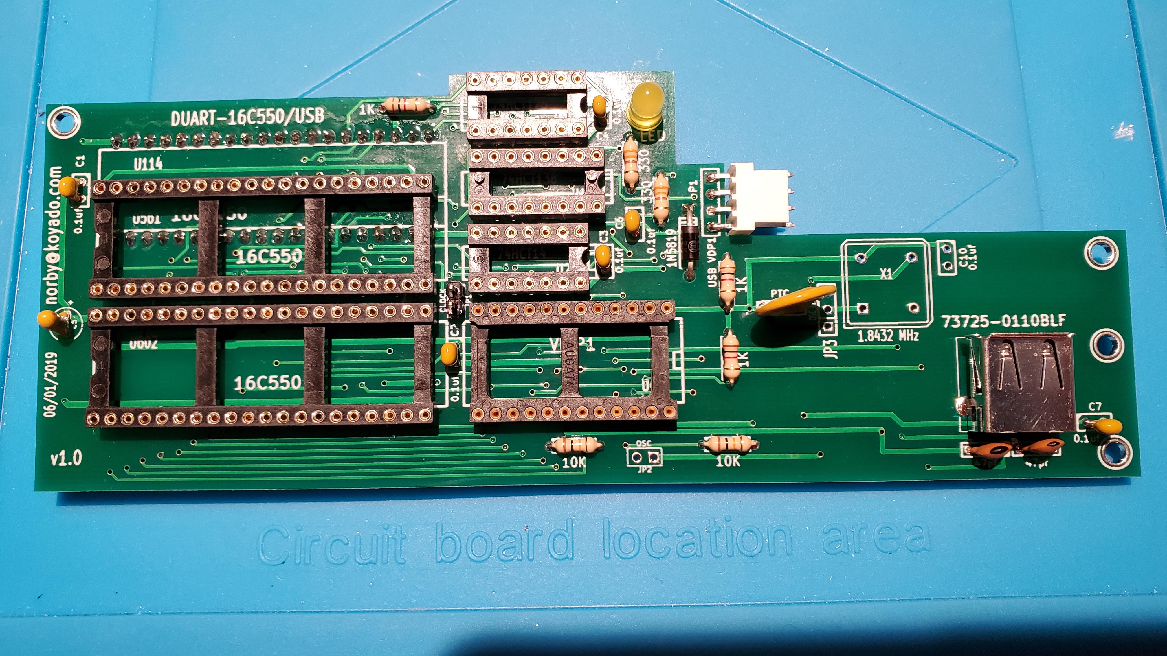
I started the DUART board and ran into a snag.
I am using these instructions: H8-Z80-V3_1-DUART-Assembly instructions.pdf
Step 1, solder the V4 / DUART header.
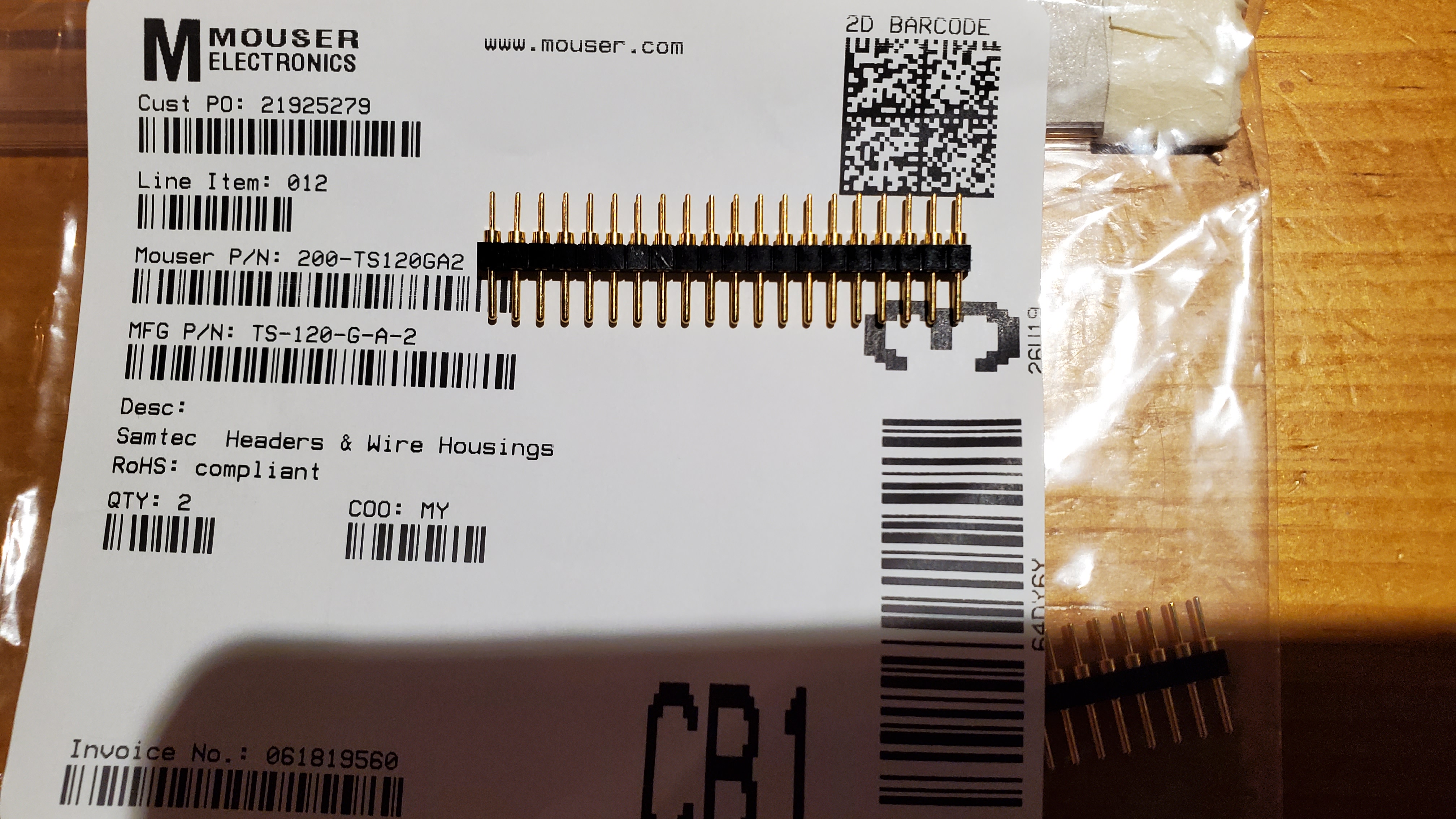
I ordered TS-120-G-A-2 for the DUART 20-pin Header.
One end of this header will not fit the socket on the V4 OR the DUART board holes.
The photo shows the header.
The pins with the cylindrical base will fit both the V4 socket and the holes in the DUART board.
The straight pins will not fit either board. The pins don't fit by a lot.
Did I order the wrong part or am I missing something more fundamental?

On Tuesday, June 22, 2021 at 6:11:08 AM UTC-4 Gery Kissel wrote:
Glad you took the time to look at them!
On Tue, Jun 22, 2021, 1:34 AM <norberto...@koyado.com> wrote:
Glad that you shared such photo to avoid burning out the 12v regulators. 😊
From: se...@googlegroups.com <se...@googlegroups.com> On Behalf Of Gery Kissel
Sent: Monday, June 21, 2021 12:49 PM
To: SEBHC <se...@googlegroups.com>
Subject: Re: [sebhc] Gery's V4 Build Adventure
Green light!
Thanks again to Norberto and Terry for catching my TO92 case orientation screw up. I guess I am going to have to re take the master builder test!
I got everything switched around correctly and applied power.
Supplies all working correctly. Did a general sanity check for 5V around the board.
I hopefully will get to starting the DUART board tomorrow.
On Monday, June 21, 2021 at 6:20:48 AM UTC-4 Gery Kissel wrote:
To view this discussion on the web visit https://groups.google.com/d/msgid/sebhc/7103e22b-e06c-49d4-9962-106bbee3c584n%40googlegroups.com.
Gery Kissel
Glenn Roberts
Here are the connectors I used
Measuring with my micrometer the pins with the cylindrical shoulder ring appear to be .64mm (.025”) in diameter; the longer pins are .46 mm (.018”) in diameter. The ones with the shoulder are soldered into the PC board; the longer narrower pins plug into the 40-pin socket on the CPU board. The shouldered pin length is 4.3mm (.17”); the narrower pin length is 4.75mm (.186”).
I recall having trouble finding the right part here. Norberto recommended this part
https://groups.google.com/g/sebhc/c/WZmRSwGvLNM/m/7dMmbavuAQAJ
I think this is more of the discussion:
https://groups.google.com/g/sebhc/c/SRP5OUD9Jec/m/bzUv0lQXFQAJ
sorry, since I had bought these parts a while ago I didn’t think to mention this. At a glance I didn’t see any part spec’ed for this in the BOM? But perhaps we should update that?
Looking at the Mouser data sheet
it looks like the correct part would end in “-A” but you bought “-A-1”?, though that part appears to have different pin lengths than the one I used.
I believe you should be able to test your board by simply plugging in the 16C550 UART in the 40-pin receptacle on the CPU board (and possibly changing some jumpers, e.g. disabling the second com port and/or VDIP1?). that would let you test things if you have to wait for more parts…
- Glenn
From: se...@googlegroups.com <se...@googlegroups.com> On Behalf Of Gery Kissel
Sent: Tuesday, June 22, 2021 4:03 PM
To: SEBHC <se...@googlegroups.com>
Subject: Re: [sebhc] Gery's V4 Build Adventure
A little advice from the experts please....
I started the DUART board and ran into a snag.
I am using these instructions: H8-Z80-V3_1-DUART-Assembly instructions.pdf
Step 1, solder the V4 / DUART header.
I ordered TS-120-G-A-2 for the DUART 20-pin Header.
One end of this header will not fit the socket on the V4 OR the DUART board holes.
The photo shows the header.
The pins with the cylindrical base will fit both the V4 socket and the holes in the DUART board.
The straight pins will not fit either board. The pins don't fit by a lot.
Did I order the wrong part or am I missing something more fundamental?

On Tuesday, June 22, 2021 at 6:11:08 AM UTC-4 Gery Kissel wrote:
Glad you took the time to look at them!
On Tue, Jun 22, 2021, 1:34 AM <norberto...@koyado.com> wrote:
Glad that you shared such photo to avoid burning out the 12v regulators. 😊
From: se...@googlegroups.com <se...@googlegroups.com> On Behalf Of Gery Kissel
Sent: Monday, June 21, 2021 12:49 PM
To: SEBHC <se...@googlegroups.com>
Subject: Re: [sebhc] Gery's V4 Build Adventure
Green light!
Thanks again to Norberto and Terry for catching my TO92 case orientation screw up. I guess I am going to have to re take the master builder test!
I got everything switched around correctly and applied power.
Supplies all working correctly. Did a general sanity check for 5V around the board.
I hopefully will get to starting the DUART board tomorrow.
On Monday, June 21, 2021 at 6:20:48 AM UTC-4 Gery Kissel wrote:
.
To view this discussion on the web visit https://groups.google.com/d/msgid/sebhc/7103e22b-e06c-49d4-9962-106bbee3c584n%40googlegroups.com.
terry.smedley
Terry Smedley
https://www.amazon.com/dp/B0778TFL39
Terry
Gery Kissel
Terry Smedley
Gery Kissel
Terry Smedley
Glenn Roberts
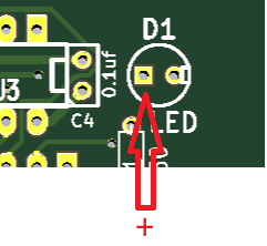
The flat side is the cathode or negative terminal. The lead on the positive (anode) side is usually longer so put the longer lead into the hole with the “+” sign.
To view this discussion on the web visit https://groups.google.com/d/msgid/sebhc/fb90caed-66dd-41f6-928d-06f5d2816786n%40googlegroups.com.
Gery Kissel
To view this discussion on the web visit https://groups.google.com/d/msgid/sebhc/031c01d76a28%24fd4eb970%24f7ec2c50%24%40gmail.com.
norberto...@koyado.com
Always the Square hole is pin 1. My bad and I’m sorry that I didn’t use the correct LED symbol.
Thanks,
To view this discussion on the web visit https://groups.google.com/d/msgid/sebhc/CAK6523vdhFeyeHu3GcEnrQh%3Dz2cj3nZpFpjN_P239EE302BiLQ%40mail.gmail.com.
Gery Kissel
Douglas Miller
Maybe this is common practice, but I got in the habit of
"pre-forming" pins before inserting the ICs. From the factory, the
angle of the pins is far too wide for sockets, so I'd hold the IC
by the ends against a hard, flat surface and then bend slightly,
flip over and do the other side. Takes a bit of practice to get
the right amount of bend, but makes the insertion go much easier.
To view this discussion on the web visit https://groups.google.com/d/msgid/sebhc/67357ad6-8784-434a-bbdb-184b4446cca7n%40googlegroups.com.
Gery Kissel
To view this discussion on the web visit https://groups.google.com/d/msgid/sebhc/41a4f0bd-ca5f-badf-240e-b531a69001cd%40gmail.com.
Glenn Roberts
Yes that’s the trick! My understanding is the angle on the pins is to accommodate automated insertion equipment but I’ve never understood why that is…
From: se...@googlegroups.com <se...@googlegroups.com> On Behalf Of Douglas Miller
Sent: Saturday, June 26, 2021 7:08 PM
To: se...@googlegroups.com
Subject: Re: [sebhc] Gery's V4 Build Adventure
Maybe this is common practice, but I got in the habit of "pre-forming" pins before inserting the ICs. From the factory, the angle of the pins is far too wide for sockets, so I'd hold the IC by the ends against a hard, flat surface and then bend slightly, flip over and do the other side. Takes a bit of practice to get the right amount of bend, but makes the insertion go much easier.
On 6/26/21 5:55 PM, Gery Kissel wrote:
Session 12 done. Have to say the most difficult session out of them all up until now.
Got the jumpers on and the DIP switches set. Thanks Terry for checking my settings for me last week.
I am way out of practice installing ICs. "Back in the day" which in this case is late 80's, I had a side job upping memory cards for folks. A great side gig in college at a time everyone wanted their blazing 386s maxed out. I would put 100-200 memory chips a day and never bend a pin.
Which for the most part is how things went but so far I have installed 2 of the 20 pin chips and bent pins on both. What a pain.
Anyway enough of that for the day.
Hope not to bend anymore tomorrow and hopefully finish.
To view this discussion on the web visit https://groups.google.com/d/msgid/sebhc/41a4f0bd-ca5f-badf-240e-b531a69001cd%40gmail.com.

Dave McGuire
The as-shipped "spread" of the pins provides spring force to hold the
IC in the insertion fixture as it moves over the board toward its
destination position. Nowadays we use vacuum fixtures for stuff like
that, but it was a good approach that worked well.
-Dave
On 6/26/21 10:01 PM, Glenn Roberts wrote:
> Yes that’s the trick! My understanding is the angle on the pins is to
> accommodate automated insertion equipment but I’ve never understood why
> that is…
>
>
>
>
>
>
>
> *Douglas Miller
> *Sent:* Saturday, June 26, 2021 7:08 PM
> *To:* se...@googlegroups.com
> *Subject:* Re: [sebhc] Gery's V4 Build Adventure
>
>
> Maybe this is common practice, but I got in the habit of "pre-forming"
> pins before inserting the ICs. From the factory, the angle of the pins
> is far too wide for sockets, so I'd hold the IC by the ends against a
> hard, flat surface and then bend slightly, flip over and do the other
> side. Takes a bit of practice to get the right amount of bend, but makes
> the insertion go much easier.
>
> On 6/26/21 5:55 PM, Gery Kissel wrote:
>
> Session 12 done. Have to say the most difficult session out of them
> all up until now.
>
> Got the jumpers on and the DIP switches set. Thanks Terry for
> checking my settings for me last week.
>
>
>
> I am way out of practice installing ICs. "Back in the day" which in
> this case is late 80's, I had a side job upping memory cards for
> folks. A great side gig in college at a time everyone wanted their
> blazing 386s maxed out. I would put 100-200 memory chips a day and
> never bend a pin.
>
>
>
> Which for the most part is how things went but so far I have
> installed 2 of the 20 pin chips and bent pins on both. What a pain.
>
> Anyway enough of that for the day.
>
> Hope not to bend anymore tomorrow and hopefully finish.
>
>
>
>
>
>
> Always the Square hole is pin 1. My bad and I’m sorry that I
> didn’t use the correct LED symbol.
>
>
>
>
>
>
> Norberto
>
>
>
> *From:* se...@googlegroups.com <se...@googlegroups.com> *On
> Behalf Of *Gery Kissel
> *Sent:* Friday, June 25, 2021 7:10 PM
> *To:* se...@googlegroups.com
> *Subject:* Re: [sebhc] Gery's V4 Build Adventure
>
>
> My board does not have polarity marks or flatty side graphic. I
> assumed that the square pad was positive but just wanted to make
> sure.
>
> Thanks.
>
>
>
>
>
> On Fri, Jun 25, 2021, 9:17 PM Glenn Roberts
> <glenn.f...@gmail.com> wrote:
>
> The flat side is the cathode or negative terminal. The lead
> on the positive (anode) side is usually longer so put the
> longer lead into the hole with the “+” sign.
>
>
>
> Behalf Of *Terry Smedley
> *Sent:* Friday, June 25, 2021 3:25 PM
> *To:* SEBHC <se...@googlegroups.com>
> *Subject:* Re: [sebhc] Gery's V4 Build Adventure
>
>
> Flatty to the right is ..... right.
>
>
>
> Terry
>
>
>
> On Friday, June 25, 2021 at 12:18:15 PM UTC-7
> gkisselsp...@gmail.com wrote:
>
> I am finishing up the DUART board. Before I make a
> mistake, what is the correct orientation of the "flatty"
> side of D1 LED?
>
> I am guessing to the right.
>
>
>
> On Wednesday, June 23, 2021 at 11:58:30 AM UTC-4 Terry
> Smedley wrote:
>
> If you're considering building the new H8 Front
> Panel, Amazon has the ZYAMY female socket headers
> that will work nicely for the LEDs, and also mate
> with the male pin headers that Glenn referenced.
>
>
>
> ZYAMY 10pcs 2.54mm 40Pin Round Female Socket Pin
> Header Strip 1x40P Single Row Straight Female/Male
> Socket/Pin Header Strip Connector Black
> https://www.amazon.com/dp/B0778TFL39
> Terry
>
> On Tuesday, June 22, 2021 at 4:16:43 PM UTC-7 Glenn
> wrote:
>
> Here are the connectors I used
>
>
>
> Amazon.com: ZYAMY 10pcs 2.54mm Male Breakable
> Pin Header Strip 40Pin 1x40P Single Row Straight
> Gold Plated Male Pin Header Strip Connector
> Black: Electronics
>
>
> Measuring with my micrometer the pins with the
> cylindrical shoulder ring appear to be .64mm
> (.025”) in diameter; the longer pins are .46 mm
> (.018”) in diameter. The ones with the shoulder
> are soldered into the PC board; the longer
> narrower pins plug into the 40-pin socket on the
> CPU board. The shouldered pin length is 4.3mm
> (.17”); the narrower pin length is 4.75mm (.186”).
>
>
>
> I recall having trouble finding the right part
> here. Norberto recommended this part
>
> https://groups.google.com/g/sebhc/c/WZmRSwGvLNM/m/7dMmbavuAQAJ
>
>
>
> I think this is more of the discussion:
>
> https://groups.google.com/g/sebhc/c/SRP5OUD9Jec/m/bzUv0lQXFQAJ
>
> sorry, since I had bought these parts a while
> ago I didn’t think to mention this. At a glance
> I didn’t see any part spec’ed for this in the
> BOM? But perhaps we should update that?
>
>
>
> Looking at the Mouser data sheet
>
> ts-1360359.pdf (mouser.com)
>
>
> it looks like the correct part would end in “-A”
> but you bought “-A-1”?, though that part appears
> to have different pin lengths than the one I used.
>
>
>
> I believe you should be able to test your board
> by simply plugging in the 16C550 UART in the
> 40-pin receptacle on the CPU board (and possibly
> changing some jumpers, e.g. disabling the second
> com port and/or VDIP1?). that would let you
> test things if you have to wait for more parts…
>
>
>
>
>
>
>
>
> *From:* se...@googlegroups.com
> <se...@googlegroups.com> *On Behalf Of *Gery Kissel
> *Sent:* Tuesday, June 22, 2021 4:03 PM
> *To:* SEBHC <se...@googlegroups.com>
> *Subject:* Re: [sebhc] Gery's V4 Build Adventure
>
>
> A little advice from the experts please....
>
>
>
> I started the DUART board and ran into a snag.
>
> I am using these
> instructions: H8-Z80-V3_1-DUART-Assembly
> instructions.pdf
>
> Step 1, solder the V4 / DUART header.
>
>
>
> I ordered TS-120-G-A-2 for the DUART 20-pin Header.
>
>
>
> One end of this header will not fit the socket
> on the V4 OR the DUART board holes.
>
> The photo shows the header.
>
> The pins with the cylindrical base will fit both
> the V4 socket and the holes in the DUART board.
>
> The straight pins will not fit either board.
> The pins don't fit by a lot.
>
>
>
> Did I order the wrong part or am I missing
> something more fundamental?
>
>
>
>
>
>
>
>
>
> Gery Kissel wrote:
>
> Glad you took the time to look at them!
>
>
>
> On Tue, Jun 22, 2021, 1:34 AM
> <norberto...@koyado.com> wrote:
>
> Glad that you shared such photo to avoid
> burning out the 12v regulators. 😊
>
>
>
> <se...@googlegroups.com> *On Behalf Of
> *Gery Kissel
> *Sent:* Monday, June 21, 2021 12:49 PM
> *To:* SEBHC <se...@googlegroups.com>
> *Subject:* Re: [sebhc] Gery's V4 Build
> <se...@googlegroups.com> *On
> Behalf Of *Gery Kissel
> *Sent:* Sunday, June 20, 2021
> 12:57 PM
> *To:* SEBHC <se...@googlegroups.com>
> *Subject:* Re: [sebhc] Gery's V4
> --
>
> You received this message
> because you are subscribed to a
> topic in the Google Groups
> "SEBHC" group.
> To unsubscribe from this topic,
> visit
> https://groups.google.com/d/topic/sebhc/WtApvdiP-cg/unsubscribe.
> To unsubscribe from this group
> and all its topics, send an
> email to
> sebhc+un...@googlegroups.com.
> To view this discussion on the
> web visit
> https://groups.google.com/d/msgid/sebhc/008b01d76668%2493469f70%24b9d3de50%24%40koyado.com
> --
> You received this message because you
> are subscribed to the Google Groups
> "SEBHC" group.
> To unsubscribe from this group and stop
> receiving emails from it, send an email
> to sebhc+un...@googlegroups.com.
> To view this discussion on the web visit
> <https://groups.google.com/d/msgid/sebhc/f8688b59-402a-4304-879d-3d4584f6b463n%40googlegroups.com?utm_medium=email&utm_source=footer>.
> --
> You received this message because you
> are subscribed to a topic in the Google
> Groups "SEBHC" group.
> To unsubscribe from this topic, visit
> https://groups.google.com/d/topic/sebhc/WtApvdiP-cg/unsubscribe.
> To unsubscribe from this group and all
> its topics, send an email to
> sebhc+un...@googlegroups.com.
>
> To view this discussion on the web visit
> <https://groups.google.com/d/msgid/sebhc/010301d76728%243fca1500%24bf5e3f00%24%40koyado.com?utm_medium=email&utm_source=footer>.
> --
> You received this message because you are
> subscribed to the Google Groups "SEBHC" group.
> To unsubscribe from this group and stop
> receiving emails from it, send an email to
> sebhc+un...@googlegroups.com
>
> .
> To view this discussion on the web visit
> https://groups.google.com/d/msgid/sebhc/7103e22b-e06c-49d4-9962-106bbee3c584n%40googlegroups.com
> --
> You received this message because you are subscribed to the
> Google Groups "SEBHC" group.
> To unsubscribe from this group and stop receiving emails
> from it, send an email to sebhc+un...@googlegroups.com.
> To view this discussion on the web visit
> <https://groups.google.com/d/msgid/sebhc/fb90caed-66dd-41f6-928d-06f5d2816786n%40googlegroups.com?utm_medium=email&utm_source=footer>.
> --
> You received this message because you are subscribed to a
> topic in the Google Groups "SEBHC" group.
> To unsubscribe from this topic, visit
> https://groups.google.com/d/topic/sebhc/WtApvdiP-cg/unsubscribe.
> To unsubscribe from this group and all its topics, send an
> email to sebhc+un...@googlegroups.com.
> To view this discussion on the web visit
> <https://groups.google.com/d/msgid/sebhc/031c01d76a28%24fd4eb970%24f7ec2c50%24%40gmail.com?utm_medium=email&utm_source=footer>.
> --
> You received this message because you are subscribed to the
> Google Groups "SEBHC" group.
> To unsubscribe from this group and stop receiving emails from
> it, send an email to sebhc+un...@googlegroups.com.
>
> To view this discussion on the web visit
> <https://groups.google.com/d/msgid/sebhc/CAK6523vdhFeyeHu3GcEnrQh%3Dz2cj3nZpFpjN_P239EE302BiLQ%40mail.gmail.com?utm_medium=email&utm_source=footer>.
> --
> You received this message because you are subscribed to the Google
> Groups "SEBHC" group.
> To unsubscribe from this group and stop receiving emails from it,
> send an email to sebhc+un...@googlegroups.com
> <https://groups.google.com/d/msgid/sebhc/67357ad6-8784-434a-bbdb-184b4446cca7n%40googlegroups.com?utm_medium=email&utm_source=footer>.
> --
> You received this message because you are subscribed to the Google
> Groups "SEBHC" group.
> To unsubscribe from this group and stop receiving emails from it, send
> an email to sebhc+un...@googlegroups.com
> <https://groups.google.com/d/msgid/sebhc/41a4f0bd-ca5f-badf-240e-b531a69001cd%40gmail.com?utm_medium=email&utm_source=footer>.
> --
> You received this message because you are subscribed to the Google
> Groups "SEBHC" group.
> To unsubscribe from this group and stop receiving emails from it, send
> an email to sebhc+un...@googlegroups.com
> <https://groups.google.com/d/msgid/sebhc/011e01d76af8%2467d27b40%24377771c0%24%40gmail.com?utm_medium=email&utm_source=footer>.
--
Dave McGuire, AK4HZ
New Kensington, PA
Douglas Miller
the pin spread, since the ICs are still being made with that pin angle.
I also need to "jostle" the IC in the socket to make sure that the pins
have meshed with the socket, before doing the final press for insertion.
Glenn Roberts
Sent from my iPad
> On Jun 26, 2021, at 10:05 PM, Dave McGuire <mcg...@neurotica.com> wrote:
>
>
Douglas Miller
that were directly soldered to the PCB - flex the pins and insert into
PCB, then release and the IC stays in-place for soldering. Wave
soldering may have eliminated the need for that as gravity would also
keep the IC from falling out.

Joseph Travis
To view this discussion on the web visit https://groups.google.com/d/msgid/sebhc/011e01d76af8%2467d27b40%24377771c0%24%40gmail.com.

dwight
Sent: Saturday, June 26, 2021 7:53 PM
To: se...@googlegroups.com <se...@googlegroups.com>
Subject: Re: [sebhc] Gery's V4 Build Adventure
norberto...@koyado.com
but we found that vibration and heat cycling tended to cause them to walk out of the sockets.
The Z80 CPU on my H8 Z80 baseboard will come out by itself after several days when using the machined tooled sockets. It was easy to reproduced. After taking out the CPU IC and straightened the leads it stopped doing that. Very strange behavior.
Norby
To view this discussion on the web visit https://groups.google.com/d/msgid/sebhc/BYAPR01MB5319213EA4672B8DAA61AB14A3049%40BYAPR01MB5319.prod.exchangelabs.com.
Gery Kissel
norberto.collado koyado.com
Sent: Sunday, June 27, 2021 1:25 PM
To: SEBHC <se...@googlegroups.com>
dwight
Sent: Sunday, June 27, 2021 6:24 AM
Gery Kissel
Terry Smedley
Glenn Roberts
On Jun 29, 2021, at 4:31 PM, Terry Smedley <terry....@gmail.com> wrote:
Gery:
To view this discussion on the web visit https://groups.google.com/d/msgid/sebhc/c6e12bce-062d-4299-9bdd-2541c41ae72dn%40googlegroups.com.
norberto.collado koyado.com
Sent: Tuesday, June 29, 2021 3:34 PM
norberto...@koyado.com
Nicely done and beautiful system.
Norby
From: se...@googlegroups.com <se...@googlegroups.com> On Behalf Of Gery Kissel
Sent: Tuesday, June 29, 2021 12:59 PM
To: SEBHC <se...@googlegroups.com>
Subject: Re: [sebhc] Gery's V4 Build Adventure
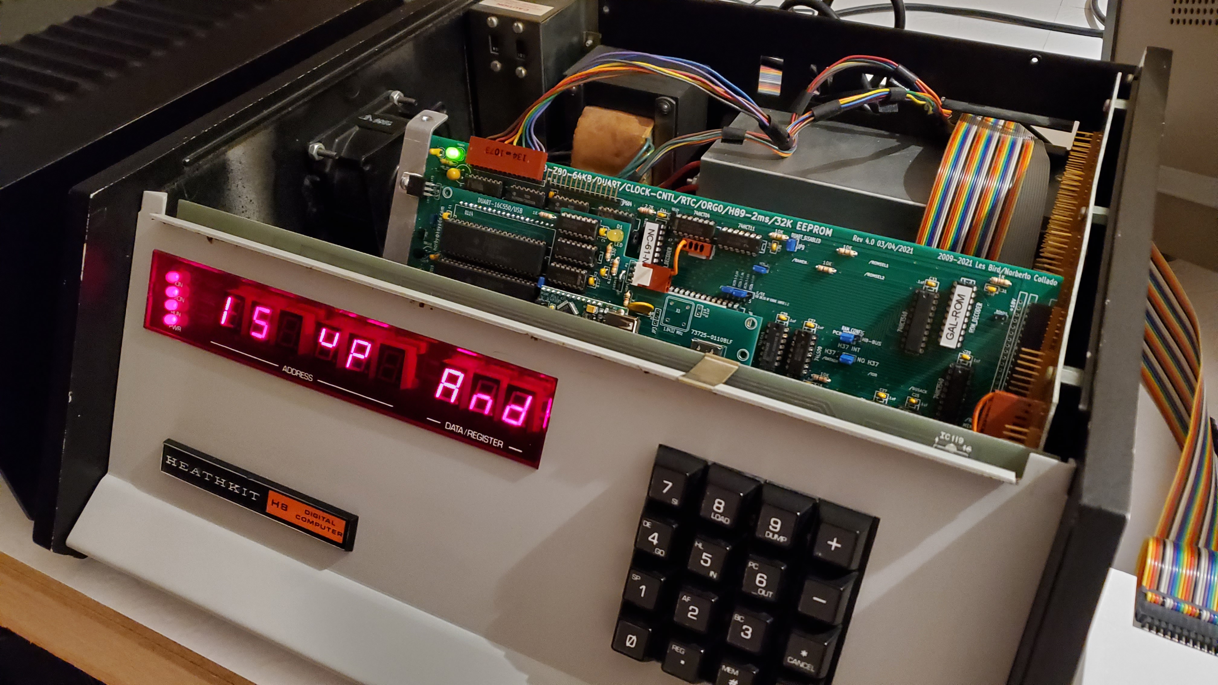
Success!

To view this discussion on the web visit https://groups.google.com/d/msgid/sebhc/88a1e97b-aa9a-458e-a94e-cb137efa47den%40googlegroups.com.
Glenn Roberts
On Jun 29, 2021, at 7:14 PM, norberto.collado koyado.com <norberto...@koyado.com> wrote:
To view this discussion on the web visit https://groups.google.com/d/msgid/sebhc/SN6PR01MB385585A81F6B2BC39E712D73F7029%40SN6PR01MB3855.prod.exchangelabs.com.
Gery Kissel
85-1938-1 8080 CPU card
85-2197-1 16k Static RAM card
H8-5 Cassette / Serial Interface card
Universal Data Systems external 300 baud direct connect modem
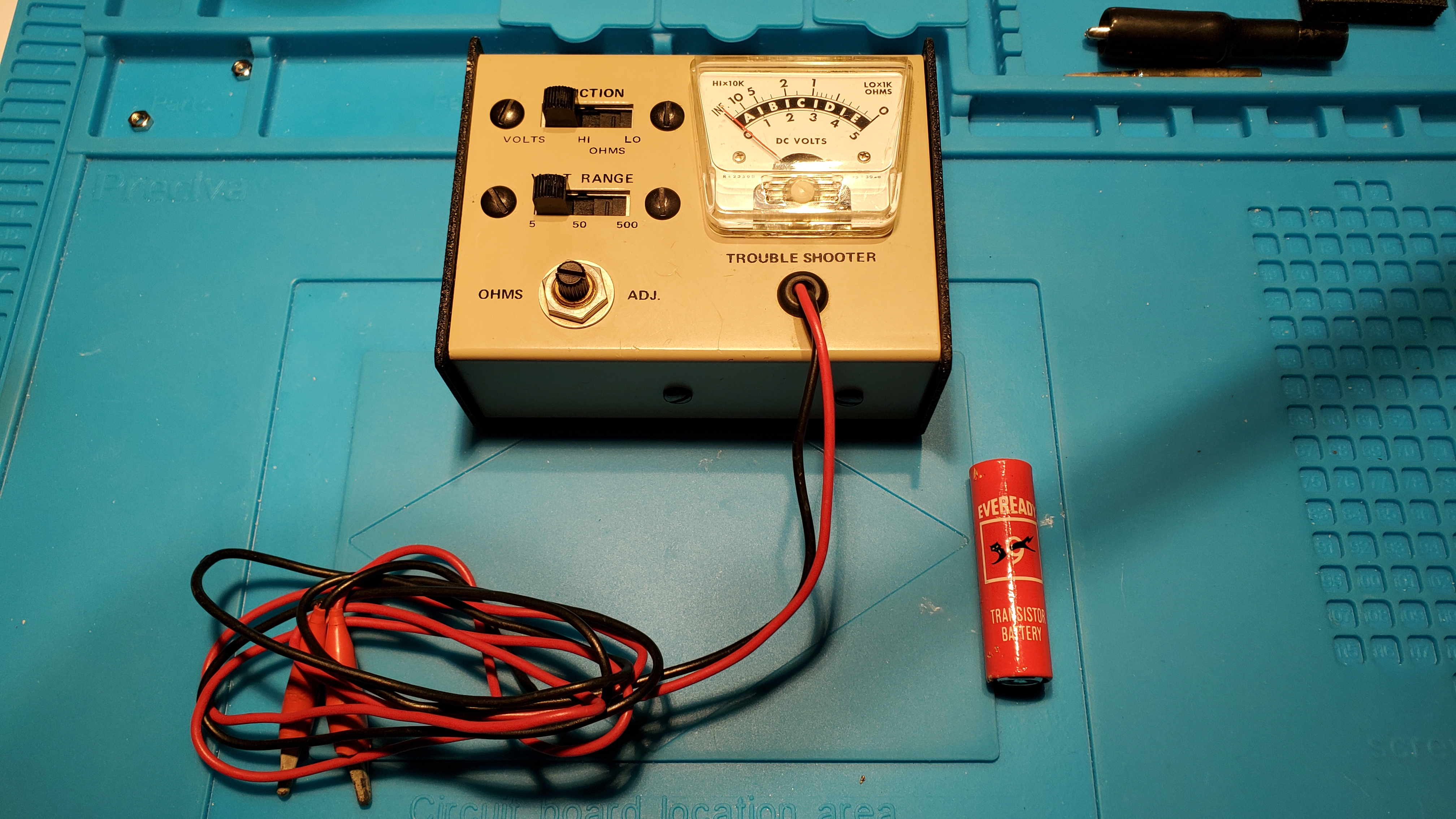
None of the cards have been used since about 1985. That is interesting but what I found more interesting was this old Heath meter that was part of my Heathkit GR-400 TV I built before building my H8 system.
But MOST interesting was the battery in the picture. That is the original battery circa 1978. The open circuit voltage is 1.5V and a battery test meter still says its "good".
In some ways I think that battery has faired better than I have!
Gery
Glenn Roberts
Seeing that red energizer brought back a lot of memories. I used to feed those things to my little GE transistor radio all the time (mostly because I’d fall asleep with it under the pillow still playing… WABC… Cousin Brucie… 😊 )
From: se...@googlegroups.com <se...@googlegroups.com> On Behalf Of Gery Kissel
Sent: Friday, July 09, 2021 9:50 AM
To: SEBHC <se...@googlegroups.com>
Subject: Re: [sebhc] Gery's V4 Build Adventure
Yesterday I was going through boxes in my back room and found a box with:
85-1938-1 8080 CPU card
85-2197-1 16k Static RAM card
H8-5 Cassette / Serial Interface card
Universal Data Systems external 300 baud direct connect modem
None of the cards have been used since about 1985. That is interesting but what I found more interesting was this old Heath meter that was part of my Heathkit GR-400 TV I built before building my H8 system.
But MOST interesting was the battery in the picture. That is the original battery circa 1978. The open circuit voltage is 1.5V and a battery test meter still says its "good".
In some ways I think that battery has faired better than I have!
Gery
To view this discussion on the web visit https://groups.google.com/d/msgid/sebhc/fde95d8a-a743-4956-8dfd-be4b2deba93cn%40googlegroups.com.

Steven Hirsch
> Seeing that red energizer brought back a lot of memories. I used to feed
> those things to my little GE transistor radio all the time (mostly because
> I’d fall asleep with it under the pillow still playing… WABC… Cousin
> Brucie… 😊 )
>
Jean Shepard (WINS 1010, I think). The little GE radio turned up at the
bottom of a box in my attic and I hope to clean it up and repair at some point.