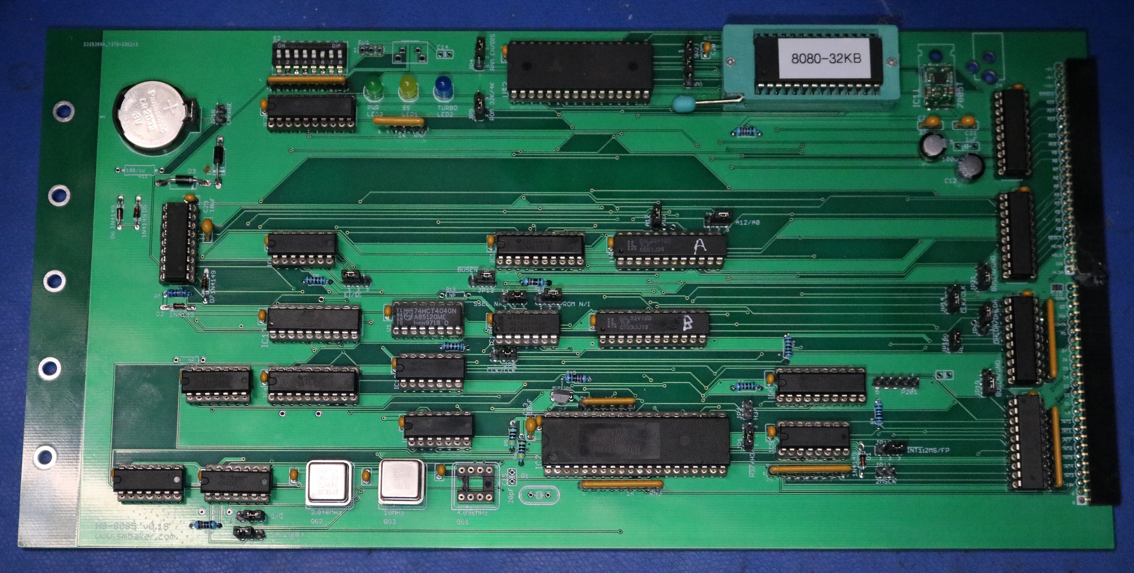
H8-8085 CPU Board

smb...@gmail.com
- Intel 8085, 2 MHz or 4 MHz, software switchable and usable with H17 gearshift driver
- Optional 5 MHz (or faster) instead of 4 MHz if you're willing to live a little dangerously
- 4K or 32K ROM
- 64K Onboard RAM
- ORG0
- 2ms clock stuff lifted from the Z80 board schematic
- Generation of M1 and EI/DI decoding
- HOLD/HLDA supported, like the original
- RTC
- Ought to support H37, but untested yet

norberto.collado koyado.com
Very nice Scott. Simple and elegant.
I have on my hand several 8085 CPU’s from the 80’s and I was thinking on using them on the 8080A board. You read my mind. I will be interested on the schematics, PDL’s files, and KiCad files to add the DUART 40 pin socket, so that it doesn’t depend on the H8-4 board to work properly.
Which monitor are you using? Hopefully it can run same monitor we are using on the new 8080A board supported by Douglas.
For H37 support you will need to add two jumpers. On my 8080A they are labeled: JP29 (two pin header) and JP30 (three pin header).
Schematics here: http://koyado.com/heathkit/New-H8-Website/download/h8-8080a-eeprom-schematics%20(1).pdf
Thanks for sharing and nicely done,
Norberto
--
You received this message because you are subscribed to the Google Groups "SEBHC" group.
To unsubscribe from this group and stop receiving emails from it, send an email to
sebhc+un...@googlegroups.com.
To view this discussion on the web visit
https://groups.google.com/d/msgid/sebhc/2ca6a8f3-d0e9-4f24-aa50-f87a78c8d024n%40googlegroups.com.
smb...@gmail.com
norberto.collado koyado.com
Very nice and thank you!
To view this discussion on the web visit https://groups.google.com/d/msgid/sebhc/b078b7b8-1d36-4616-8698-dcd53af2d478n%40googlegroups.com.

Joseph Travis
To view this discussion on the web visit https://groups.google.com/d/msgid/sebhc/SN6PR01MB38558F99F7F2559D01E92686F7AE9%40SN6PR01MB3855.prod.exchangelabs.com.
smb...@gmail.com
Joseph Travis
To view this discussion on the web visit https://groups.google.com/d/msgid/sebhc/bec75d0e-8fa7-406c-bb02-c6199294c3a7n%40googlegroups.com.
norberto.collado koyado.com
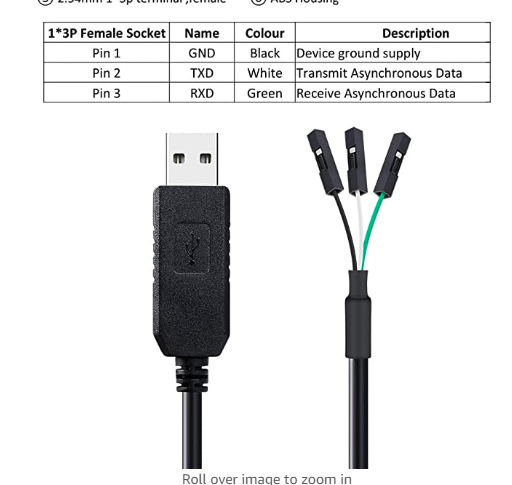
Just add a 3-pin header to use this cable:
To view this discussion on the web visit https://groups.google.com/d/msgid/sebhc/CAGQDgBC%3DQQPiUtmBf%3DBQvExXCFqS8Gjy6AdqqMO%3DoWrw60CE-Q%40mail.gmail.com.

Douglas Miller
Great, Scott!
Let me know if there is any specialized code needed for the 8085
- I can add that as a build option for the 8080A monitor (similar
to what I do for the Z80/Z180 version). Might be nice, though, if
one version fits all.
To view this discussion on the web visit https://groups.google.com/d/msgid/sebhc/b078b7b8-1d36-4616-8698-dcd53af2d478n%40googlegroups.com.
Douglas Miller
I will say, based on a little experiment I did recently, that
using SID/SOD as a general-purpose RS-232 port is not all that
practical. Especially for receive operations, it requires
dedicated CPU time - i.e. you can't receive asynchronously and
still do other tasks. Perhaps highly specialized debugging, but
again, the CPU really can't do much else at the time. Think about
it in contrast to having a UART that can detect the START bit and
receive the character bits while the CPU is not looking - with
SID/SOD if the CPU misses the START bit you've lost the characters
so you really have to be spinning on SID all the time. So you
almost need to work out some sort of "I want to talk" protocol
that interrupts the CPU and starts it spinning on SID to receive
the command, then goes back to "useful" work.
Still, it's a good idea to have the headers on the board for anyone that wants to use it. Similar to what I think was done for some of the extra devices on the Z180.
To view this discussion on the web visit https://groups.google.com/d/msgid/sebhc/SN6PR01MB3855C13CA16E3D4916D398F8F7AE9%40SN6PR01MB3855.prod.exchangelabs.com.
smb...@gmail.com
smb...@gmail.com

glenn.f...@gmail.com
Always enjoy your videos Scott. Had to chuckle at the small mound of JLCPCB boxes in the background. You’ve been keeping them busy!
From: se...@googlegroups.com <se...@googlegroups.com> On Behalf Of smb...@gmail.com
Sent: Monday, March 20, 2023 11:02 AM
To: SEBHC <se...@googlegroups.com>
Subject: Re: [sebhc] H8-8085 CPU Board
Norberto, schematics and PLDs are now current at https://github.com/sbelectronics/h8/tree/master/h8-8085
Possibly a regression though -- 8085 board gave me some trouble using the Dual CF board yesterday. It was hanging right after loading the HA device driver, unless I moved the CF and CPU boards one slot closer together on the bus (yeah, physical distance between the two boards was a trigger). Not sure if that points at a design problem in the 8085 board or an implementation issue -- I'm not as careful with my VCC routing as you are one your boards; maybe I have a bus transceiver that is getting marginal voltage. Need to play with it a bit and root cause it. Maybe next weekend.
Youtube video is up at https://www.youtube.com/watch?v=u7ECUqSSfcU briefly walks through the design, though it leaves all the really complicated stuff (i.e. PLD equations, generating M!, single-stepper, etc) out. In this video I also spend some time showing off the dual-CF card, and gripe about the DRAM board.
Scott
On Sunday, 26 February 2023 at 11:52:49 UTC-8 smb...@gmail.com wrote:
Douglas, the only noteworthy thing I'm missing in the monitor is the code to change speeds. I have 1 bit of speed control implemented, so I only have two speeds (0=normal and 1=fast). In theory the same code as the Z80 board should do this. If the set of boards continues to grow, then each board might offer a slightly different set of speeds than the others -- both quantity of speeds and the absolute MHz of each speed.
For the next revision I'll make a note to expose the SID and SOD pins. It looks like if nothing else, we could blink an LED or read a switch with them :) This is exactly what I did with the MI and MO pins on my Z8000 project. It's like a little bonus 1-bit GPIO.
Scott
On Sunday, 26 February 2023 at 05:21:17 UTC-8 Douglas Miller wrote:
I will say, based on a little experiment I did recently, that using SID/SOD as a general-purpose RS-232 port is not all that practical. Especially for receive operations, it requires dedicated CPU time - i.e. you can't receive asynchronously and still do other tasks. Perhaps highly specialized debugging, but again, the CPU really can't do much else at the time. Think about it in contrast to having a UART that can detect the START bit and receive the character bits while the CPU is not looking - with SID/SOD if the CPU misses the START bit you've lost the characters so you really have to be spinning on SID all the time. So you almost need to work out some sort of "I want to talk" protocol that interrupts the CPU and starts it spinning on SID to receive the command, then goes back to "useful" work.
Still, it's a good idea to have the headers on the board for anyone that wants to use it. Similar to what I think was done for some of the extra devices on the Z180.
On 2/26/23 01:55, norberto.collado koyado.com wrote:
Just add a 3-pin header to use this cable:

To view this discussion on the web visit https://groups.google.com/d/msgid/sebhc/d37f6a8b-5070-45c2-8495-9d44f7c00327n%40googlegroups.com.
smb...@gmail.com
Joseph Travis
To view this discussion on the web visit https://groups.google.com/d/msgid/sebhc/2f86c8d1-c2fe-4a1f-8a52-dde0b3fe2735n%40googlegroups.com.
smb...@gmail.com
norberto.collado koyado.com
Thank you and impressive video!
To view this discussion on the web visit https://groups.google.com/d/msgid/sebhc/d37f6a8b-5070-45c2-8495-9d44f7c00327n%40googlegroups.com.

Lee Hart
To view this discussion on the web visit https://groups.google.com/d/msgid/sebhc/SN6PR01MB3855DDBA4804A10FE24B885DF7819%40SN6PR01MB3855.prod.exchangelabs.com.