Control and Adjustement of Scale

59 views
Skip to first unread message

Edward Mccann

unread,
Jan 20, 2022, 9:17:01 PM1/20/22
to sark110
I am not able to adjust scale of say, VSWR, when I want to have the axis read 1 to 5 instead of 1 to 10 while on PC Computer Control Mode.

I seem to recall being able to adjust the scale in  past iterations of Firmware, but perhaps I am mistaken.

Can someone jog my memory? Or have I installed something or forgotten a step?

Thank you,

Ed McCann
AG6CX

Gregory Neil Winterflood

unread,
Jan 20, 2022, 9:50:36 PM1/20/22
to sar...@googlegroups.com
Gday Ed,

It took me a while to see that one needs to enter changes in the top and bottom boxes as I have indicated in the attachment.

I hope this is the right answer!

73 de Greg VK8MD

Dr Gregory Winterflood [Ret]
BA MBBS DA DRCOG MPH
5 Burke Street
EAST SIDE 
Northern Territory
Australia                0870


--
You received this message because you are subscribed to the Google Groups "sark110" group.
To unsubscribe from this group and stop receiving emails from it, send an email to sark110+u...@googlegroups.com.
To view this discussion on the web visit https://groups.google.com/d/msgid/sark110/ed5e6a22-f1df-4222-8b3c-73d331342975n%40googlegroups.com.
Scales .png

melchor...@gmail.com

unread,
Jan 21, 2022, 6:43:04 AM1/21/22
to sar...@googlegroups.com

Hello Ed,


For adjusting manually the scale, please ensure that the ‘Auto Range’ checkbox is not set; see the screenshot below:


Best regards,

Melchor EA4FRB

--

image001.png

Edward Mccann

unread,
Jan 24, 2022, 1:31:35 PM1/24/22
to sar...@googlegroups.com
I misinterpreted “reset”.

I saw to range in default at 10:1

I entered my  range, 4-1, and hit reset.

Bounced back to 10:1

I failed to understand I was changing scale to 4, requiring an OK, not a “reset”

Pilot error. All set.

Thanks Melchor and Greg.

New issue:

My markers M1 and M2 seem to be working, but are both the same color.

I attach picture of my Sark 110 vs page 21 of the User’s Manual. Color scheme does not seem to matter, in White markers are same.

Would be convenient to restore to two-color marker scheme. 

Suggestions?

Thank you,
Ed McCann
AG6CX


Sent from my iPhone

On Jan 21, 2022, at 3:43 AM, melchor...@gmail.com wrote:


Edward Mccann

unread,
Jan 24, 2022, 1:32:51 PM1/24/22
to sar...@googlegroups.com
With picture:


Sent from my iPhone

On Jan 24, 2022, at 10:31 AM, Edward Mccann <edwm...@gmail.com> wrote:

I misinterpreted “reset”.

melchor...@gmail.com

unread,
Jan 24, 2022, 2:11:17 PM1/24/22
to sar...@googlegroups.com

Hello Ed,


Thank you for your suggestion.


Indeed, I will adjust the colors of markers to be better distinguishable.


Also, I will correct a bug for tracking markers when used for peak detection.

image001.png

Edward Mccann

unread,
Jan 24, 2022, 7:33:35 PM1/24/22
to sar...@googlegroups.com
Melchor:

Sorry to bother you again.

I  beginning to think something has gotten corrupted.
Attached scan of Rs and Xs with M1.
M1 shows Rho in polar form.

I didn’t select to have anything centered, and CT has popped in on its own.

Something appears amiss.

Look forward to your suggestions.

Ed McCann
AG6CX

Sent from my iPhone

Edward Mccann

unread,
Jan 24, 2022, 9:53:03 PM1/24/22
to sar...@googlegroups.com


Sent from my iPhone

On Jan 24, 2022, at 4:33 PM, Edward Mccann <edwm...@gmail.com> wrote:

Melchor:

melchor...@gmail.com

unread,
Jan 25, 2022, 11:49:30 AM1/25/22
to sar...@googlegroups.com

Hello Ed,


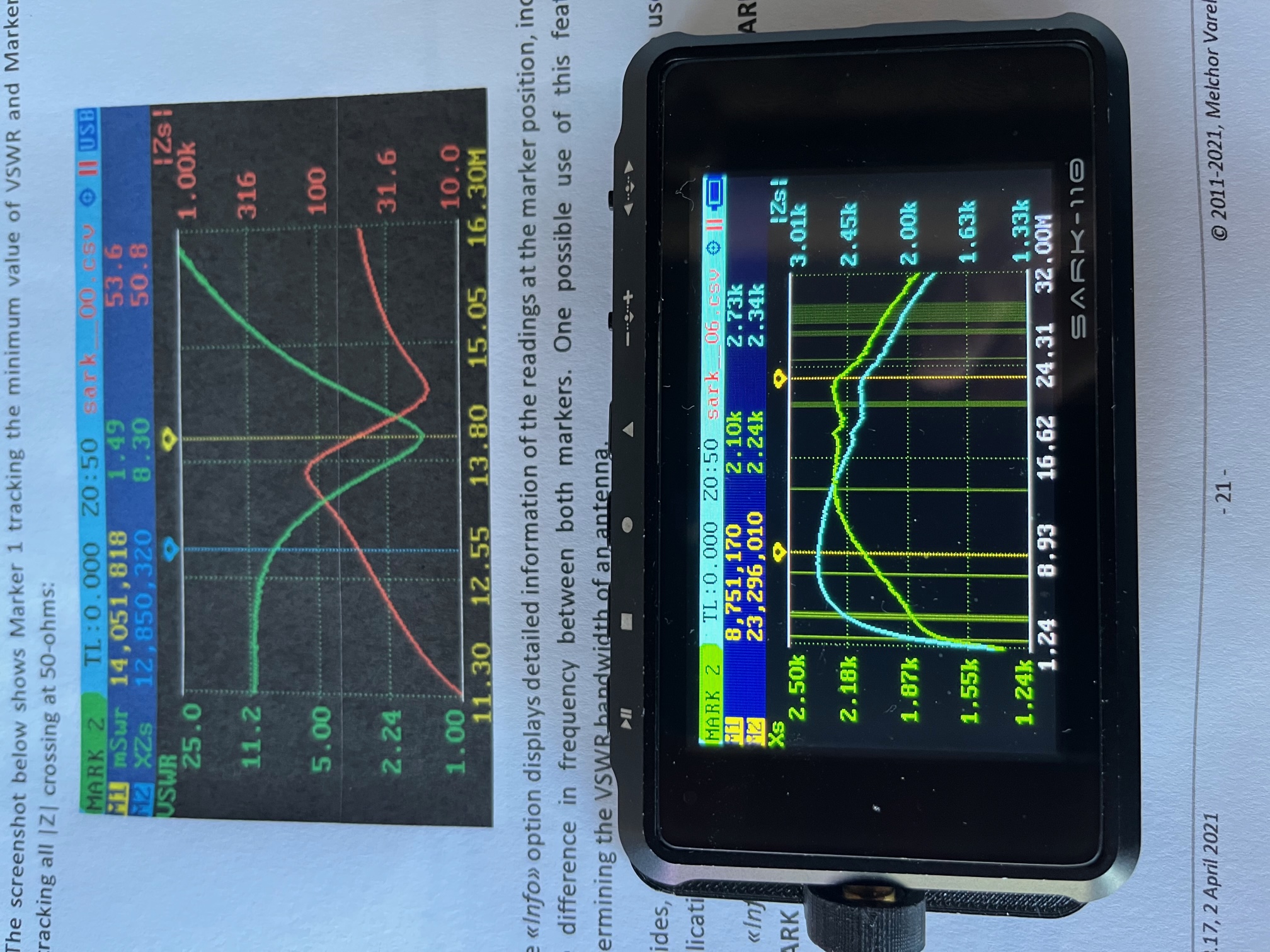
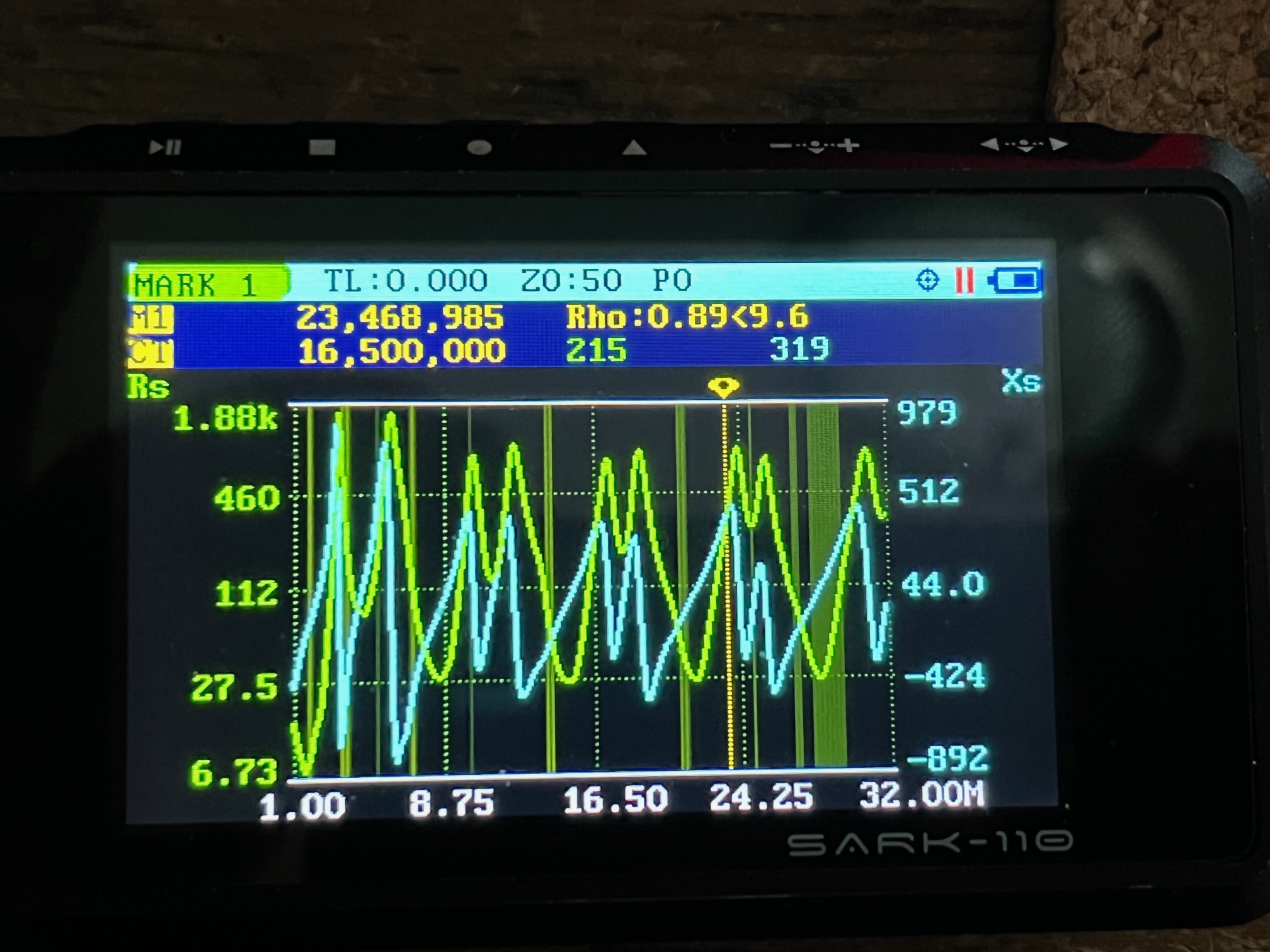
The markers menu (Marker 1 or Marker 2) has the ‘Data’ option that allows selecting the data to be display at marker positions. You can select to display the plotted values, the impedance in rectangular or polar forms, and the reflection coefficient in rectangular or polar forms.


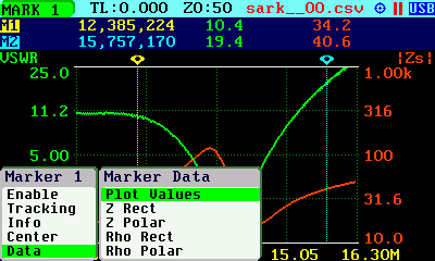
In your screenshot, Marker 1 is displaying the reflection coefficient in polar form.


The second marker shows CT, because it has selected to be in disabled state. In the disabled state it shows the readings at the center of the span (CT is used as abbreviation of center here).

image002.jpg
image003.png
image001.png

Edward Mccann

unread,
Jan 25, 2022, 12:17:01 PM1/25/22
to sar...@googlegroups.com
Melchor:

Makes perfect sense as explained.

I didn’t notice in the operating Gide that if disabled, the Marker default is to center. Must have missed it.

Nor did I realize I needed to select “Plot Values” on Data. 

I must learn to read more accurately!!

Unit run and is working as advertised.

Thanks again for such great support.

Ed McCann
AG6CX

Sent from my iPhone

Edward Mccann

unread,
Feb 28, 2022, 7:51:59 PM2/28/22
to sark110
Hello Melchor (and group):

Using SarkPlots,  trying to characterize a ferrite torid balun, I came across what appeared to be an anomaly, and came up with  a question unrelated to that anomaly.

1. First to the Anomaly:

 Running a plot of Rs vs Frequency, I added  markers to various frequencies, including 2.770 MHz, 3.848 MHz and 4.327 MHz, among others. You can see the corresponding values for Rs and Xs are 2890 and 4468 ohms and 6473 and 4383 ohms and 8103  ohms and 3364 ohms respectively.

Exporting the data in SarkPlots i saved the Excel Spreadsheet, and noticed that the data for the frequencies of interest were transposed up one line from the line of the corresponding frequency. To make the matter clear, I attach a scans marked to show this displacement. I also attach copies of the jpg plot and Excel workbook to aid your review.

I did not check all the frequencies and corresponding data, but assume if they were transposed up one line for the frequencies of interest, the other lines are likely misaligned as well. I did note that the Text document reflects the same issue for the three frequencies I chose.

While it may well be a computer problem, here, I hadn't noticed it before.

2. The Question.

I also noticed the ability to export S11 and S21 data from SarkPLots, which I had not done before.
Given that the Sark 110 appears to be a a one port VNA, could you explain the default entries for S21 and Angle S21,units used,  and why they are included. I may be missing something. You will find copies of the associated JPGs in the zipped file.


Thanks Melchor.

Ed McCann
AG6CX
Choke E226 Sark 20200226.zip

melchor...@gmail.com

unread,
Mar 1, 2022, 12:28:32 PM3/1/22
to sar...@googlegroups.com

Hello Edward,


I have reviewed your files and have noted the anomaly you described. Let me investigate where the problem is, and I’ll get back to you as soon as possible.


On the S21 entries, this is because SARK Plots was designed to support two-port devices, regardless the Sark-110 is a single-port device.

Edward Mccann

unread,
Mar 1, 2022, 12:34:14 PM3/1/22
to sar...@googlegroups.com
Thanks Melchor.

As an aside, I occasionally notice a lag on navigator switch (in either direction) as I attempt to move marker 1 or 2 up or down in frequency.

Is that an internal Sark electronics matter, or indication of a switch needing a shot of electronic cleaner?

Or?

Thanks, and best regards.

Ed McCann
AG6CX 


Sent from my iPhone

On Mar 1, 2022, at 9:28 AM, melchor...@gmail.com wrote:


melchor...@gmail.com

unread,
Mar 1, 2022, 12:53:25 PM3/1/22
to sar...@googlegroups.com

This can be due to a dusty contact. A cleaner such as IPA should be good for fixing it.

Edward Mccann

unread,
Mar 1, 2022, 9:06:06 PM3/1/22
to sar...@googlegroups.com
Deep breath.
Cover removed.
IPA gently applied.
Cover replaced.
Problem solved.

Thanks Melchor.


Sent from my iPhone

On Mar 1, 2022, at 9:53 AM, melchor...@gmail.com wrote:


Reply all
Reply to author
Forward
0 new messages