Patch antennas as feeds
86 views
Skip to first unread message

Marcus D. Leech
Mar 6, 2023, 3:11:34 PM3/6/23
to Society of Amateur Radio Astronomers
Just watched the latest RTOP video.
There was a discussion of patch antennas as dish feeds. We're using a
circular patch to feed our 12.8m dish--because
they're quite compact. But ours is *air supported* -- making it very
low loss.
But a *printed* patch antenna, as was discussed, will be
lossy---particularly on 0.062" FR4. One could re-scale to
use 0.031" FR4 material, which would lower the dielectric losses, but
not eliminate them. The printed form of a patch
is certainly appealing for mass-production and convenience but the
loss is a "gotcha". Also, they're quite narrowband--
which is a good benefit in many situations, but won't allow you to
extend it to 1612MHz.
We got our circular-patch from Sub-Lunar systems--they're not cheap as
coffee or anything, but not gold-toilet horrific.

Alex P
Mar 12, 2023, 4:09:53 PM3/12/23
to Society of Amateur Radio Astronomers
Hello Marcus,
Bob was showing that as
1) a successful 3-D printed design by one of his student friends and
2) as the antenna of a reference Tx source he was considering building.
...... not as an RT system feed.
Cheers,
Alex

Dimitry UA3AVR
Mar 13, 2023, 3:29:50 AM3/13/23
to Society of Amateur Radio Astronomers
Hi all,
FR4 is not a good material regarding losses. PTFE based laminates (like from AD series by Rogers) are better. The best dielectric is air, certainly :)).
With greetings & regards, Dimitry UA3AVR.
понедельник, 6 марта 2023 г. в 23:11:34 UTC+3, Marcus D. Leech:

duncan campbell-wilson
Mar 14, 2023, 3:45:45 AM3/14/23
to sara...@googlegroups.com
Hi,
The issue about feed losses has two parts
(1) The surface quality :
The skin depth determines where the currents travel in the copper (typical 35 um) of the PCB material. Poor surface quality gives rise to an ohmic loss.
The top few microns of the conducting material at UHF is critical. I would recommend silver plated copper on the PCB and a conformal protective coating.
(2) A double sided PCB with many vias can be thought of as a solid plate where the currents flow on the surfacea and the dielectric is effective only at the edges of the board.
I have attached a short paper for your interest. A longer paper by Meiling Deng is available from UBC in Canada
Rgds Duncan
--
--
You received this message because you are subscribed to the Google
Groups "Society of Amateur Radio Astronomers" group.
To post to this group, send email to sara...@googlegroups.com
To unsubscribe from this group, send email to
sara-list-...@googlegroups.com
For more options, visit this group at
http://groups.google.com/group/sara-list?hl=en
---
You received this message because you are subscribed to the Google Groups "Society of Amateur Radio Astronomers" group.
To unsubscribe from this group and stop receiving emails from it, send an email to sara-list+...@googlegroups.com.
To view this discussion on the web visit https://groups.google.com/d/msgid/sara-list/a97182f8-40e7-4ebb-852e-6f77ca155c6dn%40googlegroups.com.

Brad Thomas
Mar 14, 2023, 8:42:20 AM3/14/23
to sara...@googlegroups.com
I've had success at 70cm with circular patch antennas, air-gapped,
made with solid aluminum pizza pans. The upper plate is a 14 or 15
inches, circular. The bottom is similar, but 20 inches. They are
air-gapped using 1 inch nylon stand-offs. The placement of the probe
was determined using Ansys HFSS. In the end, the antennas were checked
out using a vector network analyzer and matched simulations quite
well. They do work in practice, too.
I would like to try something similar for 21 cm, but have not done so as yet.
--Brad Thomas
> To view this discussion on the web visit https://groups.google.com/d/msgid/sara-list/CAFfhL0%3DwSYgCsQNpkKDM_Fow9AMw37vp2bDXG4Ru_kSDi3zNHg%40mail.gmail.com.
made with solid aluminum pizza pans. The upper plate is a 14 or 15
inches, circular. The bottom is similar, but 20 inches. They are
air-gapped using 1 inch nylon stand-offs. The placement of the probe
was determined using Ansys HFSS. In the end, the antennas were checked
out using a vector network analyzer and matched simulations quite
well. They do work in practice, too.
I would like to try something similar for 21 cm, but have not done so as yet.
--Brad Thomas

Jeff King
Mar 14, 2023, 9:02:14 AM3/14/23
to sara...@googlegroups.com
WHAT FREQS ON 70?
To view this discussion on the web visit https://groups.google.com/d/msgid/sara-list/CAJLdLJjP5qtszRL1ECar4LXKy0dwA5zbm08O3S_p-HiHcm5Crg%40mail.gmail.com.

Brad Thomas
Mar 14, 2023, 9:30:15 AM3/14/23
to sara...@googlegroups.com
The larger pizza pan, 15 inch, gave a peak on the VNA at 418MHz the
smaller one, 14 inch, at 445MHz. I had forgotten, so I got out my VNA
and checked just now.
--Brad
> To view this discussion on the web visit https://groups.google.com/d/msgid/sara-list/CAHqcrhRApRZ9og5J4FsJZqZKv0E7L1zVKdb01Kchv%2BVM%2BEzHug%40mail.gmail.com.
smaller one, 14 inch, at 445MHz. I had forgotten, so I got out my VNA
and checked just now.
--Brad
Brad Thomas
Mar 14, 2023, 9:32:07 AM3/14/23
to sara...@googlegroups.com
Thanks for that information on 21 cm. I'll give it a try.
--Brad
--
--
You received this message because you are subscribed to the Google
Groups "Society of Amateur Radio Astronomers" group.
To post to this group, send email to sara...@googlegroups.com
To unsubscribe from this group, send email to
sara-list-...@googlegroups.com
For more options, visit this group at
http://groups.google.com/group/sara-list?hl=en
---
You received this message because you are subscribed to the Google Groups "Society of Amateur Radio Astronomers" group.
To unsubscribe from this group and stop receiving emails from it, send an email to sara-list+...@googlegroups.com.
To view this discussion on the web visit https://groups.google.com/d/msgid/sara-list/625726672.2019347.1678799034823%40mail.yahoo.com.
Jeff King
Mar 14, 2023, 9:33:05 AM3/14/23
to sara...@googlegroups.com
PICS?
To view this discussion on the web visit https://groups.google.com/d/msgid/sara-list/CAJLdLJjHWE-rgc4rMnjENWVczZeP3M6-1gc8TL%2BvUAZRj%3DsdKg%40mail.gmail.com.
Brad Thomas
Mar 14, 2023, 9:58:41 AM3/14/23
to sara...@googlegroups.com
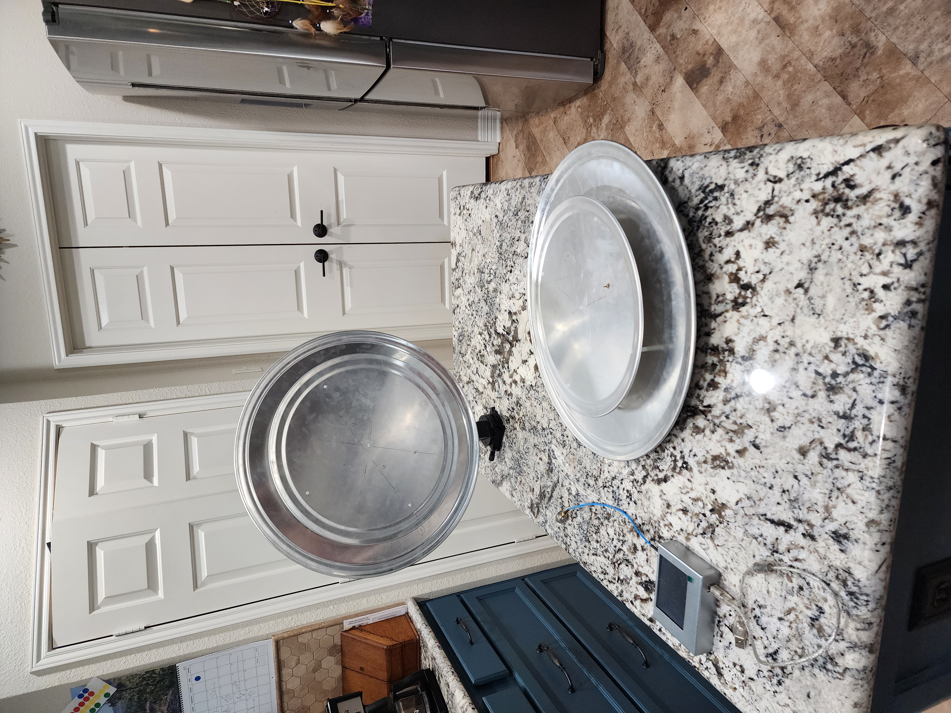
Here are two of the pizza pan circular patch antennas for 70cm. The
base is a 20 inch aluminum pan and the active plate is 15 Inch (418
MHz) or 14 inch (445 MHz). The probe is a 2.5mm threaded brass rod
that goes to an N connector. Stand-offs to provide a one inch air gap
are 1/4 inch nylon. I wondered if the raised rims might be a problem,
so included them in 3D models in HFSS software. The simulations
indicated no large effect.
--Brad Thomas
> To view this discussion on the web visit https://groups.google.com/d/msgid/sara-list/CAHqcrhQCMCj1hEFWh4RCLKQVQ%2BhQhh%2BaR2URBk8%3DrsnCmz_Sqw%40mail.gmail.com.
base is a 20 inch aluminum pan and the active plate is 15 Inch (418
MHz) or 14 inch (445 MHz). The probe is a 2.5mm threaded brass rod
that goes to an N connector. Stand-offs to provide a one inch air gap
are 1/4 inch nylon. I wondered if the raised rims might be a problem,
so included them in 3D models in HFSS software. The simulations
indicated no large effect.
--Brad Thomas

Jeff Kruth
Mar 14, 2023, 10:51:23 AM3/14/23
to sara...@googlegroups.com
Hi All!
I have been watching this topic with interest. I have worked with patches on DoD projects since 1986. There are many good books about them. Basically, in many ways, in the far field, the directivity looks the same as a dipole. But they are NOT dipoles. They are in fact, a resonant cavity structures formed by the top and bottom plates, with the dielectric in between. The losses primarily are for the volume of dielectric. Metals can only get so good, but of course, corrosion is bad. Difference in copper vs. silver will not be measurable. Make sure the metal is thick enough to support at least 3 skin depths of the signal. At 1.4 Ghz, less of a problem than 400 MHz where the wavelength is .75 m.
Dielectric > 1 has the benefit of shrinking the patch size due to the foreshortening of wavelength due to the dielectric. However any dielectric constant greater than air (vacuo) in Er is going to have a loss tangent associated with it and so the EFFICIENCY of the feed goes down. In RA this can be important. That's why air dielectric feeds are so good, but so big. Rogers material for dielectric filled patches with Er > 1, is very good. Crane Polyflon pure Teflon copper clad material is GREAT but Er is only 2.2 or so so th reduction in size is not much.
Additionally the feed illumination angle is better (smaller) in air dielectric feeds.
The feed beamwidth should be matched to the disk illumination angle. Dipole-like feed work best in f/D ratio dishes less than .25 (Angle about 180 degrees).
Most "figure of revolution" parabolas for sat work are .36 or so (feed angle about 120 degrees or so for 12 dB edge taper).
Offset fed dishes (parabolic segments) have f/D ratios greater than this (about .5-.7) so need horns with tighter beamwidth and smaller illumination angles.
Patches with wider beamwidth (thats why they are great for GPS, full sky coverage) may OVER illuminate a dish, causing spillover and allowing :thermal pollution" from the ground, etc to raise your system noise temperature to levels that mask weak sources.
However, I am also a ham and a life member of SARA. So try your feeds out. If they work for you, great! I just wanted to present some additional data. Anyway, I could go on but I have bored you enough.
J.Kruth
To view this discussion on the web visit https://groups.google.com/d/msgid/sara-list/CAFfhL0%3DwSYgCsQNpkKDM_Fow9AMw37vp2bDXG4Ru_kSDi3zNHg%40mail.gmail.com.
Jeff King
Mar 14, 2023, 10:56:49 AM3/14/23
to sara...@googlegroups.com
DID YOU PUT THE CONDUCTOR ON ONE AND BRAID ON THE OTHER?
To view this discussion on the web visit https://groups.google.com/d/msgid/sara-list/1888544710.3775976.1678805477001%40mail.yahoo.com.
Jeff Kruth
Mar 14, 2023, 11:07:28 AM3/14/23
to sara...@googlegroups.com
Well, yes, you have to!
Usually the feed point mechanism is critical and can be complicated as the center of the patch is 0 ohms and the impedance increases to several hundred ohms or so at the edge.
The braid goes to the ground plane, and the center goes to the top plate (at the right place of course). I also wanted to say that match is not the best indicator of performance of any antenna. I teach my Senior level students that it is important for the optimum flow of energy from the antenna to the receiver, of course, but it is not the only thing.
Remember that a resistor can have a great "match" but is a lousy antenna.
One of the simplest ways to see if your antenna is any good is to see how well it radiates. By reciprocity, an antenna transmits exactly as well as it receives.
So a metal plate about 1 wavelength or so across,is a great test of radiation. I wave it in front of the antenna in a radial path to see if the antenna radiates well. It will show in VSWR (or return loss) on a NA. You can see the R.L. change as the antenna moves thru several wavelength excursions. This can give you an idea of how well the antenna works.
J. Kruth
To view this discussion on the web visit https://groups.google.com/d/msgid/sara-list/CAHqcrhTaYhGC%2BD65V03X5ZDdUpvkFsQ81qQdXB_uKPsNA0Pp5w%40mail.gmail.com.
Marcus D. Leech
Mar 14, 2023, 11:21:16 AM3/14/23
to sara...@googlegroups.com
On 14/03/2023 09:54, Brad Thomas wrote:
> Here are two of the pizza pan circular patch antennas for 70cm. The
> base is a 20 inch aluminum pan and the active plate is 15 Inch (418
> MHz) or 14 inch (445 MHz). The probe is a 2.5mm threaded brass rod
> that goes to an N connector. Stand-offs to provide a one inch air gap
> are 1/4 inch nylon. I wondered if the raised rims might be a problem,
> so included them in 3D models in HFSS software. The simulations
> indicated no large effect.
>
> --Brad Thomas
Here's my 611MHz pizza-and-cake-pan patch feed:
> Here are two of the pizza pan circular patch antennas for 70cm. The
> base is a 20 inch aluminum pan and the active plate is 15 Inch (418
> MHz) or 14 inch (445 MHz). The probe is a 2.5mm threaded brass rod
> that goes to an N connector. Stand-offs to provide a one inch air gap
> are 1/4 inch nylon. I wondered if the raised rims might be a problem,
> so included them in 3D models in HFSS software. The simulations
> indicated no large effect.
>
> --Brad Thomas
https://photos.app.goo.gl/d6ZUuSQnsYfnaYhP6
It worked fine. But the RFI at the site was insane, and we had maybe 1
day in 10 where things were quiet. So, gave up on
611MHz, despite it being "protected".
b alex pettit jr
Mar 15, 2023, 8:31:29 AM3/15/23
to 'Jeff Kruth' via Society of Amateur Radio Astronomers
Hello Jeff,
Perhaps you can give insight into the current distribution / radiation pattern of a Patch vs Loop Feed ??
The WiFi para-grid dish is highly polarized and a polarized Feed only works in one orientation.
What surprised me was that the Patch needed to be oriented such that drive point was 90 degrees wrt the Loop for it to function.
( the blue polygon representing the baseplate/choke ring )
1) Full Wave Loop Feed
2) Circular Patch Feed

Regards,
Alex KK4VB
=========================================================================
On Tuesday, March 14, 2023 at 10:51:24 AM EDT, 'Jeff Kruth' via Society of Amateur Radio Astronomers <sara...@googlegroups.com> wrote:
Hi All!
I have been watching this topic with interest. I have worked with patches on DoD projects since 1986. There are many good books about them. Basically, in many ways, in the far field, the directivity looks the same as a dipole. But they are NOT dipoles. They are in fact, a resonant cavity structures formed by the top and bottom plates, with the dielectric in between. < big snip >
J.Kruth
Reply all
Reply to author
Forward
0 new messages