Airspy mini & RTLSDR splitter

Job Geheniau


Paul Oxley
--
You received this message because you are subscribed to the Google
Groups "Society of Amateur Radio Astronomers" group.
To post to this group, send email to sara...@googlegroups.com
To unsubscribe from this group, send email to
sara-list-...@googlegroups.com
For more options, visit this group at
http://groups.google.com/group/sara-list?hl=en
---
You received this message because you are subscribed to the Google Groups "Society of Amateur Radio Astronomers" group.
To unsubscribe from this group and stop receiving emails from it, send an email to sara-list+...@googlegroups.com.
To view this discussion on the web visit https://groups.google.com/d/msgid/sara-list/888d2695-3d43-4b28-a0b7-fd046d5fe44en%40googlegroups.com.

Mario A. Natali
Hello Job,
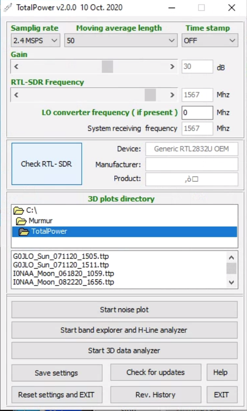
TotalPower is designed to work only with rtl-sdr as of now.
Maybe later on I will consider to extend to other SDR if I will see interest.
Thanks for using Total Power !
Mario
From: sara...@googlegroups.com <sara...@googlegroups.com> On Behalf Of Job Geheniau
Sent: domenica 25 aprile 2021 18:42
To: Society of Amateur Radio Astronomers <sara...@googlegroups.com>
Subject: [SARA] Airspy mini & RTLSDR splitter
Hi Community,
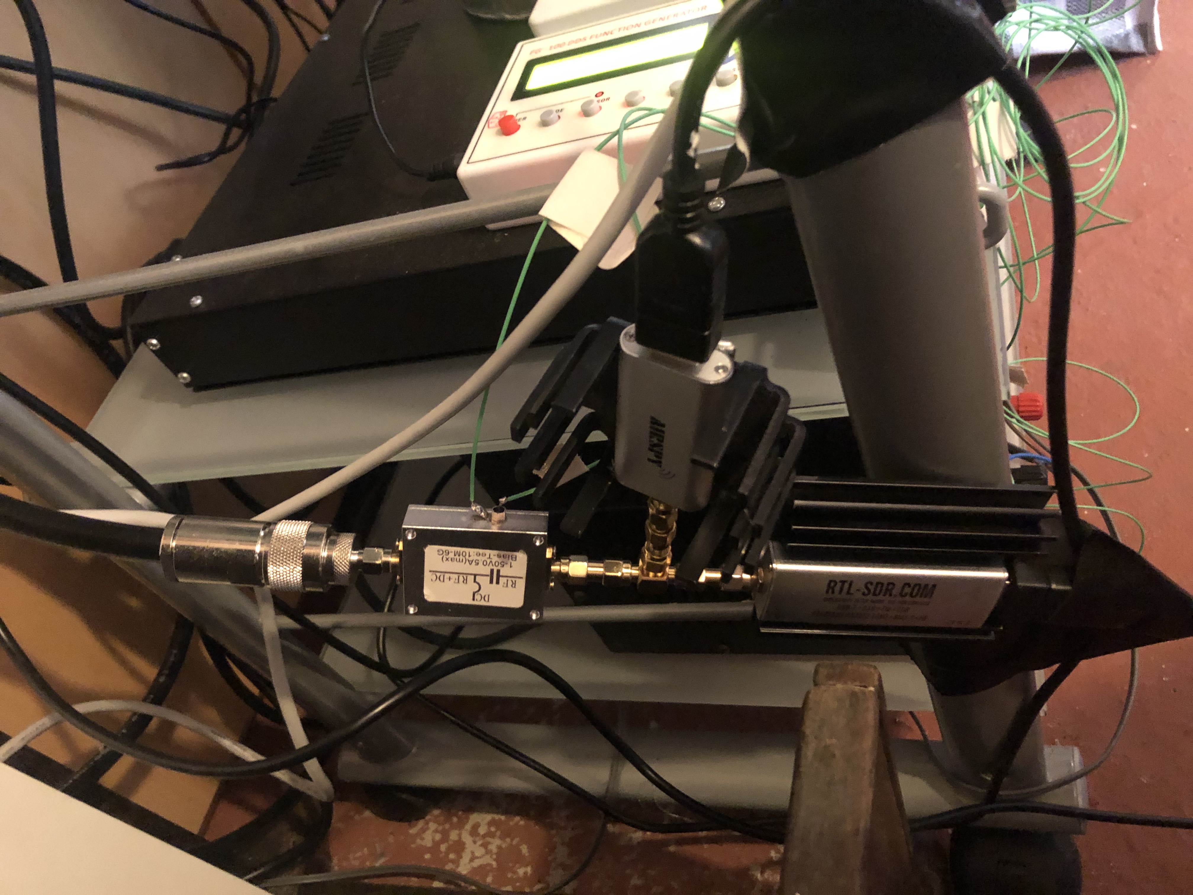
Short question, is this allowed and possible (besides I guess 3 dB loss)?
Because I can use airspy mini with sdr# and rtl with Virgo.
But Total Power seems not to work....
Job Geheniau


jpett...@gmail.com
Job
It looks like the rtl-sdr is not installed properly. When it is, the manufacturer and product will read Realtek and RTL2838UHIDIR respectively (next to the Check RTL-SDR button).
Jonathan
From: sara...@googlegroups.com <sara...@googlegroups.com> On Behalf Of Job Geheniau
Sent: Sunday, April 25, 2021 11:42 AM
To: Society of Amateur Radio Astronomers <sara...@googlegroups.com>
Subject: [SARA] Airspy mini & RTLSDR splitter
Hi Community,
Short question, is this allowed and possible (besides I guess 3 dB loss)?
Because I can use airspy mini with sdr# and rtl with Virgo.
But Total Power seems not to work....
Job Geheniau
Mario A. Natali
Yes Jonathan you are right and sorry I missed this on the previous message.
This is something that happened to some other user. I will incorporate e detailed troubleshooting procedure in the next release of TotalPower.
Job , in the meantime, please have a look to this SignalsEverywhere YouTube video https://www.rtl-sdr.com/signalseverywhere-windows-10-usb_open_error-12-fix/
and I am pretty confident that you will be able to fix the problem !
Mario
To view this discussion on the web visit https://groups.google.com/d/msgid/sara-list/029801d739fd%241c2a1cb0%24547e5610%24%40gmail.com.
Job Geheniau
Job Geheniau
Job Geheniau

Marcus D. Leech
hmm weird, maybe its the splitter, because the RTL works perfect with sdr# and virgo for almost 2 years now....so its installed properly
bias voltage, and the splitter has a DC short in it or some such.
Otherwise, the USB/Digital side of things is completely and utterly and joyfully oblivious as to what bits and pieces of RF
plumbing you may have on the RF/analog side of the radio.
To view this discussion on the web visit https://groups.google.com/d/msgid/sara-list/31aa1bab-eca1-4f18-b840-93ffddd0ed58n%40googlegroups.com.

Shef Robotham
To view this discussion on the web visit https://groups.google.com/d/msgid/sara-list/60861B03.6030909%40gmail.com.

Lamar Owen
What you've pictured will work after a fashion; assuming the input
impedance of both the RTL-SDR and the AirSpy Mini is 50 ohms, a simple T
connector will put those inputs in parallel, causing a 2:1 impedance
mismatch (50 ohms in parallel with 50 ohms = 25 ohms). Depending upon
the gain of your amplifier and its output circuit, you could have
amplifier output detuning caused by the VSWR on the short connections.
You ideally would use three devices here:
1.) a real impedance-matched splitter with two 50-ohm outputs;
2.) two isolators for the frequencies you're observing, one for each SDR.
The isolators will present a 50-ohm impedance to the splitter, and will
isolate the two SDRs from each other. Both splitters and isolators are
somewhat frequency dependent, so you'd use the ones for your frequency
band of interest.
To help prevent amplifier output detuning, it's standard practice to put
an isolator between each amplifier in a cascade, too.
Our 26 East L-band system here, using both an RAS SpectraCyber and an
AirSpy R2 works reasonably well without the isolators on the inputs, but
I am using a real 50 ohm Minicircuits two-way splitter. If I were to
see interference from the AirSpy R2 in the SpectraCyber output I would
isolate one or both of them; it would be far more likely to see issues
coming from the AirSpy R2 than from the SpectraCyber.
In most receiver cases, input impedance isn't super important; radio
astronomy isn't 'most receiver cases.'
On 4/25/21 12:42 PM, Job Geheniau wrote:
> Hi Community,
>
> Short question, is this allowed and possible (besides I guess 3 dB loss)?
> Because I can use airspy mini with sdr# and rtl with Virgo.
> But Total Power seems not to work....
pari <https://www.pari.edu>
Lamar Owen, /Chief Technology Officer/
Pisgah Astronomical Research Institute
/A not-for-profit public organization/
Email lo...@pari.edu <mailto:lo...@pari.edu>
Telephone 828.862.5554 <tel:828.862.5554> | Fax 828.862.5877
<fax:828.862.5877>
1 Pari Drive, Rosman, NC 28772
www.pari.edu <https://www.pari.edu/>
fb <https://www.facebook.com/PARIastronomy/>ig
<https://www.instagram.com/pariastronomy/>in
<https://www.linkedin.com/company/pisgah-astronomical-research-institute/>tw
<https://twitter.com/Astronomy_PARI>yt
<https://www.youtube.com/channel/UCZ14Fw8C8DZAnTvk8IZ7yXg>
Marcus D Leech
The T820T tuner used in both RTL-SDR and AirSPY have a notional input impedance closer to 75 than 50 ohms anyway.
The benefit using a proper hybrid splitter is that there will be port to port isolation. With perfect impedance on all ports the isolation offered is close to 20dB.
Sent from my iPhone
> On Apr 26, 2021, at 9:41 AM, Lamar Owen <lo...@pari.edu> wrote:
>
> Job,
> --
> You received this message because you are subscribed to the Google
> Groups "Society of Amateur Radio Astronomers" group.
> To post to this group, send email to sara...@googlegroups.com
> To unsubscribe from this group, send email to
> sara-list-...@googlegroups.com
> For more options, visit this group at
> http://groups.google.com/group/sara-list?hl=en
> --- You received this message because you are subscribed to the Google Groups "Society of Amateur Radio Astronomers" group.
> To unsubscribe from this group and stop receiving emails from it, send an email to sara-list+...@googlegroups.com.
Paul Oxley
> To view this discussion on the web visit https://groups.google.com/d/msgid/sara-list/2812dc2f-70c4-cc6a-2ef4-96e9f5d4f7a5%40pari.edu.
--
--
You received this message because you are subscribed to the Google
Groups "Society of Amateur Radio Astronomers" group.
To post to this group, send email to sara...@googlegroups.com
To unsubscribe from this group, send email to
sara-list-...@googlegroups.com
For more options, visit this group at
http://groups.google.com/group/sara-list?hl=en
---
You received this message because you are subscribed to the Google Groups "Society of Amateur Radio Astronomers" group.
To view this discussion on the web visit https://groups.google.com/d/msgid/sara-list/91736BE3-97C3-499B-B17C-F6AC6A594614%40gmail.com.
Marcus D Leech
On Apr 26, 2021, at 12:35 PM, Paul Oxley <oxl...@att.net> wrote:
To unsubscribe from this group and stop receiving emails from it, send an email to sara-list+...@googlegroups.com.
To view this discussion on the web visit https://groups.google.com/d/msgid/sara-list/1645393280.1272125.1619454906878%40mail.yahoo.com.
Lamar Owen
the feed (the LNA needs to of course be as close as possible to the
feed, or the hybrid coupler for noise injection at the feed; every
fractional dB of loss prior to the LNA adds directly to the noise figure
of the LNA), many feet of LMR600 coax, then a polyphaser surge arrestor,
then the splitter, which is a Mini-circuits ZAPD-2, which features a
specified 25 dB isolation, with >40dB near 1420MHz (
https://www.minicircuits.com/pdfs/ZAPD-2.pdf ). The splitter's
isolation is part of the reason I haven't yet added any isolators to our
system.
On 4/26/21 12:35 PM, Paul Oxley wrote:
> Marcus
>
> I agree. However, in addition, an LNA needs to be before the splitter.
> The LNA with its low noise will provide a good signal to noise ratio
> on both ports. If it is split first, the loss in the splitter will
> degrade the S/N ratio by 3 or more dB.
>
> The gain of the LNA needs to be sufficient to overcome the loss in the
> splitter. Preferably more.
>
Paul Oxley
--
You received this message because you are subscribed to the Google
Groups "Society of Amateur Radio Astronomers" group.
To post to this group, send email to sara...@googlegroups.com
To unsubscribe from this group, send email to
sara-list-...@googlegroups.com
For more options, visit this group at
http://groups.google.com/group/sara-list?hl=en
---
You received this message because you are subscribed to the Google Groups "Society of Amateur Radio Astronomers" group.
To unsubscribe from this group and stop receiving emails from it, send an email to sara-list+unsub...@googlegroups.com.
To view this discussion on the web visit https://groups.google.com/d/msgid/sara-list/9817f4fd-f0cb-3f04-a5d6-408f0457818b%40pari.edu.
Lamar Owen
The 1.5:1 impedance mismatch between 50 and 75 ohms is usually ok. 75
ohm CATV/SAT splitters today are expected to pass cable modem signals
back upstream, which resistive splitters have a hard time doing. So the
manufacturers had to up their game.
I've read conflicting documents on the AirSpy's input impedance; I don't
think I've seen anyone who has actually measured it, or for that matter
thought it was even important to measure. The R820T2 tuner has a 75 ohm
impedance; the AirSpy doesn't use the same design as the RTL-SDR
dongles, though.
For the RTL-SDR's, both the common R820T (and T2) and the less common
E4000 tuners have a nominal input impedance of 75 ohms; this is actually
documented by Nooelec for their Smart and Smart XTR RTL-SDRs as 75 ohms
in the paper
https://www.nooelec.com/store/downloads/dl/file/id/35/product/265/e4000_r820t_tuner_comparison.pdf
Note that the dBm values are adjusted due to the difference in the input
impedance (Remark 1 in that PDF). I have a couple of the Smart XTR
devices with the E4000 for S-band work at 2.1 and 2.2GHz, above the
range of the R820T2 devices (went that route after no love shown by the
maintainers of the UHD stack for our older DBSRX daughterboards on our
old USRP 1s; eventually I'll work on a fix, but I needed a quick
receiver solution, and the NeSDR SMArt XTR fits the bill).
Thanks for reminding me about a hybrid splitter's built-in isolation; I
had forgotten that detail; that's why I hadn't put any isolators in our
L-band receive system here!
On 4/26/21 11:06 AM, Marcus D Leech wrote:
> I use CATV/SAT splitters. Decades ago, these were usually resistive splitters. But not these days. They usually have a circuit board with proper broadband transformers.
>
> The T820T tuner used in both RTL-SDR and AirSPY have a notional input impedance closer to 75 than 50 ohms anyway.
>
> The benefit using a proper hybrid splitter is that there will be port to port isolation. With perfect impedance on all ports the isolation offered is close to 20dB.
Lamar Owen
system, taking into account the already nearly 50 dB of gain in the dish
(26 meters). I have enough gain at the feed that I need 15dB of
attenuation in front of the SpectraCyber.
With the AirSpy R2, our G/T is right at 20dB/K, which is not bad
(measured using the Sun as 'hot' and the north celestial pole as
'cold'). I don't at the moment have an active calibrator noise source
at the feed due to lack of cabling to switch it on and off; I have coax
for the RF and a nearby DC power supply only. At some point I'll
reactivate a calibrator source with coupler, but it's just not been a
priority.
On 4/26/21 3:20 PM, Paul Oxley wrote:
> Lamar
>
> Sounds like a good layout. In your case, the gain of the LNA also
> needs to compensate for the loss in the coax and lightening arrestor.

Lester Veenstra
Measure the noise floor of the receiver (A/D) with the receiver input terminated. Connect LNA system (antenna pointed at cold sky) to the receiver and note the increase in noise floor due to LNA path.
At a minimum the delta should be a 15 dB increase. More ideally a 20 db (approximately) (delta) increase.
Thus the LNA / Dish system noise element is dominant in the receiver, with the recovers noise floor insignificant. (I.E., the LMA noise figure is not significantly degraded by the receivers NF )
Pad the receiver input to get close to the 20 dB increase value.
Now, make sure that this operating point( say when dish pointed at hot earth or sun ) does not cause A/D to overload (say 1E-5 to 1E-4 (PTIC) percent time in clip). If you do not have sufficient linear range between cold sky and the hottest likely object (minimal PCTIC) , use additional padding for a 15 dB target vice 20 dB.
Lester B Veenstra K1YCM MØYCM W8YCM 6Y6Y
les...@veenstras.com
452 Stable Ln (HC84 RFD USPS Mail)
Keyser WV 26726
GPS: 39.336826 N 78.982287 W (Google)
GPS: 39.33682 N 78.9823741 W (GPSDO)
Telephones:
Home: +1-304-289-6057
US cell +1-304-790-9192
Jamaica cell: +1-876-456-8898
--
You received this message because you are subscribed to the Google
Groups "Society of Amateur Radio Astronomers" group.
To post to this group, send email to sara...@googlegroups.com
To unsubscribe from this group, send email to
sara-list-...@googlegroups.com
For more options, visit this group at
http://groups.google.com/group/sara-list?hl=en
---
You received this message because you are subscribed to the Google Groups "Society of Amateur Radio Astronomers" group.
To view this discussion on the web visit https://groups.google.com/d/msgid/sara-list/4221d6d7-4b67-65d7-1822-22b7e3a67027%40pari.edu.
Lamar Owen
> ...
> E4000 tuners have a nominal input impedance of 75 ohms; this is
> actually documented by Nooelec for their Smart and Smart XTR RTL-SDRs
> as 75 ohms in the paper
> https://www.nooelec.com/store/downloads/dl/file/id/35/product/265/e4000_r820t_tuner_comparison.pdf
Actually, this is wrong. According to Nooelec's page at
https://support.nooelec.com/hc/en-us/articles/360005805834-NESDR-Series
the NESDR series all have an effective input impedance of 50 ohms. My
apologies for incorrect information.
Lamar Owen
that required an actual link budget to be calculated where dish gain is
relevant; my designs for both the L-band and S-band feeds here were done
with these additional criteria in mind as well; for this basic
discussion you're correct, dish gain isn't really relevant, sorry for
the additional confusion.
But here was my process for both the L-band and S-band feeds. If
nothing else, this documents this for me.... :-) If you don't want to
read, well, go ahead and delete.....won't hurt my feelings a bit. And
if you see that I've made an error, by all means speak up; I always
reserve the right to be wrong.
For our system on L-band, we chose the RAS-1420HP-LNA.
With the RAS LNA and its noise figure of 0.29 dB (20K) and 37dB of gain
the Tsys is dominated by the LNA temperature ( 0.29dB NF at LNA input;
37 dB gain; 175 feet LMR600 (5.775 dB loss; 3.3dB per 100' at 1500MHz) =
31.225dB total gain.
The AirSpy R2 has a published NF of 3.5 dB; using the cascaded noise
figure equation (or the handy Pasternack calculator at
https://www.pasternack.com/t-calculator-noise-figure.aspx ) yields a
total noise figure of 0.2938dB, or a noise temp of 20.3K). That's not
bad at all.
Of course, I haven't compensated yet for the splitter and lightning
arrestor; I'm going to be conservative here; the specs for the splitter
say 3.2dB insertion loss per port, and the arrestor should be less than
half a dB, but I'm going to round up to 4dB for the combinarion. This
adds to the 5.775dB loss of the 175' LMR600, making a total loss of
9.775 dB. Let's round that up to 10dB; total gain is now 27dB. What
does this do to our noise figure? System NF is now 0.3dB, or 20.7K, an
increase of 0.4K, not enough to worry about.
The S-band feed has a much longer feedline with a total measured loss of
28dB (375' LMR600 (12.375dB) plus 400 feet of Andrew LDF4-50 (11.084 dB)
plus connector and lightning arrestor losses); there's 76 dB of gain at
that feed. (Kuhne KU LNA 222 AH with a NF of 0.4dB, a gain of 30dB;
filter and isolator (cumulative insertion loss 1dB); second amp (a
Minicircuits ZX60-3018G+ with about a 2.5dB NF) with 20dB gain; second
isolator (half a dB); and third amp (Minicircuits ZRL-2400LN+) with 28dB
gain (and up to +24dBm of output, about a 0.9dB NF); and a final
isolator (another half dB) before the feedline transitions to the LMR600).
The stages were gain-staged and intercept-staged appropriately so that
even the two Sirius/XM satellites wouldn't drive the system out of
linearity. 48dB total gain once we're at the receiver position in OPS.
Input LNA NF = 0.4dB (28K); total system NF (including the filter and
isolator insertion losses) 0.4039dB (28.3K).
The NESDR products don't have published noise figures; there are some
comparison reports out there like the one referred to by
https://www.rtl-sdr.com/a-comprehensive-lab-comparison-between-multiple-software-defined-radios/
done by the SatNOGS group (direct link to the comprehensive report:
https://gitlab.com/librespacefoundation/sdrmakerspace/sdreval/-/raw/master/Report/pdf/Evaluation_of_SDR_Boards-1.0.pdf
).
TL;DR version: the RTL-SDRs don't have great noise figures, >10dB NF
near the 1420 line, and they didn't test the E4000 tuner with up to
2.3GHz tuning. The LimeSDR didn't fare much better; unfortunately I
don't have a BladeRF or a newer USRP to test with, as both have lower
noise figures. I do have a couple of the ADALM-PLUTO modules; I replaced
the 25PPM XO with a 0.5 PPM TCXO on one and an external clock input
(driven by a Leo Bodnar GPSDO) on the other; maybe I should be using
these, as they have a pretty good NF of around 5dB.
But even then, with a say 12dB NF at the SDR, my S-band design still has
an effective NF of 0.4048dB. Going to 5dB NF at the SDR won't improve
things enough to worry about.
While the rule of thumb quoted below will get you in the ballpark, it's
not that hard to work the math if you have good measurements of the
components used. I could probably have done a better job in my
engineering, but it was good enough at the time. I could probably get a
better G/T, but again it was good enough at the time.
On 4/26/21 4:52 PM, 'Lester Veenstra' via Society of Amateur Radio
Paul Oxley
--
You received this message because you are subscribed to the Google
Groups "Society of Amateur Radio Astronomers" group.
To post to this group, send email to sara...@googlegroups.com
To unsubscribe from this group, send email to
sara-list-...@googlegroups.com
For more options, visit this group at
http://groups.google.com/group/sara-list?hl=en
---
You received this message because you are subscribed to the Google Groups "Society of Amateur Radio Astronomers" group.
To view this discussion on the web visit https://groups.google.com/d/msgid/sara-list/30f670bb-64be-1161-ba77-99bd693ad366%40pari.edu.
Lester Veenstra
The secondary issue I harp on is that the setup ensures sufficient dynamic range of the A/D under actual operational conditions, typically in the SARA environment, band limited white noise. The PCTIC is a sensitive indicator of linearity.
--
You received this message because you are subscribed to the Google
Groups "Society of Amateur Radio Astronomers" group.
To post to this group, send email to sara...@googlegroups.com
To unsubscribe from this group, send email to
sara-list-...@googlegroups.com
For more options, visit this group at
http://groups.google.com/group/sara-list?hl=en
---
You received this message because you are subscribed to the Google Groups "Society of Amateur Radio Astronomers" group.
To unsubscribe from this group and stop receiving emails from it, send an email to sara-list+...@googlegroups.com.
Lamar Owen
might realize; you're very correct to protect the headroom at the SDR input.
At L-band, the biggest possible interference signal will be from GPS
satellites, with both the L1 and L2 signals close to 1420. A two-pager
on the link budget for a GPS repeater setup (at least that's what it
looks like) can be found at
https://apps.fcc.gov/els/GetAtt.html?id=110032&x=.
But then there's S-band, where the Sirius/XM radio satellites have
significantly greater signal strength than the Sun does. The link
budget for FM-6, for instance, is quite the read; 71dBW EIRP at the
transmit antenna. NOT dBm; dBW. Even with a 190.8 dB path loss from GEO
you still have an effective -119.8dBW with a 0dB gain antenna.
With a 53dB gain antenna, I have to be prepared to deal with a -66.8dBW
(-36.8dBm) signal; after the first stage I have a -6.8dBm signal (Kuhne
LNA has a P1dB of 15dBm); the filter between the first and second stage
is ~20dB down at the nearest FM-6 frequency (-26dBm, truncating the
0.8dB); second amp has 20dB gain (-6dBm); two isolators at -0.5dB each
(-7dBm); third amp +28dB (+21dBm output, still below the P1dB point by
3dB of the third amp); isolator plus feedline loss -28.5dB, rounding to
-29dB (-8dBm) at OPS. I don't make it a habit to point straight at FM-6
except for pointing verification or antenna pattern measurements (it's a
great point source to use for pattern checking, since it's a strong
enough signal to receive even near the pattern nulls and it's
geostationary), but when I do I have ~3dB of headroom in the RF chain.
That's cutting it close.
Using the ADALM-PLUTO as the SDR: its AD9363 chip has an RF input
maximum rating of +2.5dBm, so I should be ok there. To be safe, I have
an addition 6dB of attenuation prior to the input; spec sheet says a NF
of 3dB and the measurements I pointed to earlier show that's not too far
off from reality, so there's good sensitivity and a nice large dynamic
range.
On 4/27/21 10:19 AM, 'Lester Veenstra' via Society of Amateur Radio
Lester Veenstra
If you can see the A/D output directly, the values to count are simple. For example, for a 8 bit A/D, clip occurs then the A/D output is 0 or when it is 127 (0000 or 1111). If you are not able to see the raw binary output bits, than you need to determine, in whatever values your system presents results, prior to the FFT process. This can be done by overdirinf (overload), with an RF signal generator, with a sine wave in the operating frequency range.
When the sine wave overloads the A/D there will be a series of maximum steady plus values and a series of steady minimum values where you would expect to see the sine wave peak. These are the over load occurrence values, that then can be counted for a PTIC metric.
Keyser WV 26726
GPS: 39.336826 N 78.982287 W (Google)
GPS: 39.33682 N 78.9823741 W (GPSDO)
Telephones:
Home: +1-304-289-6057
US cell +1-304-790-9192
Jamaica cell: +1-876-456-8898
-----Original Message-----
From: sara...@googlegroups.com [mailto:sara...@googlegroups.com] On Behalf Of Lamar Owen
Sent: Thursday, April 29, 2021 8:20 AM
To: sara...@googlegroups.com
Subject: Re: [SARA] Airspy mini & RTLSDR splitter
--
You received this message because you are subscribed to the Google
Groups "Society of Amateur Radio Astronomers" group.
To post to this group, send email to sara...@googlegroups.com
To unsubscribe from this group, send email to
sara-list-...@googlegroups.com
For more options, visit this group at
http://groups.google.com/group/sara-list?hl=en
---
You received this message because you are subscribed to the Google Groups "Society of Amateur Radio Astronomers" group.
To unsubscribe from this group and stop receiving emails from it, send an email to sara-list+...@googlegroups.com.
Lamar Owen
> to port isolation. With perfect impedance on all ports the isolation
> offered is close to 20dB.
S-band RF chain I have a Minicircuits ZFRSC-42+ 2-way splitter to split
the signal between the spectrum analyzer (R&S FSU 26) and the various
SDR dongles under test. Now, this specific splitter is a resistive
splitter (see https://www.minicircuits.com/pdfs/ZFRSC-42+.pdf ). So,
only 6dB of isolation. I checked my stock of 2.2GHz-capable splitters;
I don't have a hybrid-based one in hand right now.
So, while testing the NESDR SMArt XTR dongle (E4000 tuner to get to
2.3GHz in S-band), I noted the spectra. The photos of the screen are a
bit large to email, so instead of attaching them here are links to view:
1.) Display on spec-an's external monitor of S-band on 26 East, splitter
only, port 1 to FSU 26, port 2 to SMArt XTR, showing significant
passband ripple even with 6dB of isolation:
https://nebula.pari.edu/index.php/s/J496CIvlv5DnppQ
2.) Same display, splitter terminated with 50 ohms on port 2:
https://nebula.pari.edu/index.php/s/YVqEcwelJt5Xu1p
3.) Same display, splitter cabled to an RYT S-band isolator, supported
on non-metallic supports and cabled to the SMArt XTR:
https://nebula.pari.edu/index.php/s/7lotvwc5rjgfoaq
(Oh, by the way, on this display terrestrial 2.1GHz RFI is easily
visible on the left, and the Sirius/XM satellite downlinks are easily
visible on the right. Antenna was at zenith for these measurements.)
Moral of the photos: I guess a 75/50 ohm mismatch can have a fairly
significant impact on even receive-only operations.....
Lamar Owen
in any of the reference works I've used (Tools of Radio Astronomy for
one, where 'clipping' is only mentioned in the context of the 'Van Vleck
Clipping Correction' for one-bit quantization). I've looked through
several references, and haven't found it; I would love a pointer to a
textbook or reference using this.
I understand the concept you describe, but the degree to which it is
applicable to modern software-defined radio backends is difficult to
really determine. Ideally you get the input as close to 0dBFS as
possible at your ADC to maximize ADC dynamic range at its input; any
clipping directly translates to distortion.
Now, the term you use in a different context
(https://groups.io/g/softrock40/topic/optimum_adc_loading/5646370),
noise power ratio (NPR) is common; Analog Devices has a tutorial on the
use of NPR at
https://www.analog.com/media/en/training-seminars/tutorials/MT-005.pdf
NPR is a proven metric through decades of use in frequency-division
multiplex telephone systems. That one I'm familiar with.
Since virtually all of the modern SDRs hide the raw ADC samples behind
some DSP hardware, most commonly decimators, determining your PTIC
metric using raw samples is not really feasible (not impossible, just
not feasible) with modern SDRs like the AirSpy R2, ADAM-Pluto, USRP, and
the RTL-SDRs.
Most of the ADCs involved in modern SDRs are sigma-delta, and that
changes things around, as the actual ADC stage in the sigma-delta ADCs
that use a one-bit converter is 'in clipping' continually. A one-bit
ADC has a 100% PTIC metric; techniques are used to gain bit depth at the
expense of sampling rate.
The AirSpy R2 and Mini both are capable of the expansion of bit depth
(the ADC output is 12-bits, but DSP can turn that into 16-bits) via
decimation in the hardware, beyond what is already done as part of the
sigma-delta ADC process. I know that bit-depth expansion via decimation
and quantization noise shaping techniques sounds like a black art; a
reasonable tutorial on the technology can be found at
https://www.analog.com/en/technical-articles/behind-the-sigma-delta-adc-topology.html
Getting access to the raw samples at the ADC with no funny behavior from
AGC or other anti-clip technologies in a modern communications SDR chip
such as the AD9363 used at the heart of the ADALM-Pluto SDR is very
difficult; other ADCs vary.
On 4/29/21 9:47 AM, 'Lester Veenstra' via Society of Amateur Radio
Lester Veenstra
You are correct that the best metric for A/D performance is the NPR. But that significantly more difficult to measure in the typical SARA environment. With one significant exception;
If the noise bandwidth of interest is significantly bandlimited with respect to the Nyquist bandwidth of the receiver (A/D)b you will be a noise floor pedestal of the noise to measured, and an out of band noise floor from the A/D. If you can see out of band noise that is corrupting the A/D noise floor, you are looking at an artifact of what NPR measres,
But that is exactly the method (NPR) I did use in the work leading to PTIC. This work involved 16 bit A/Ds, working in a 1 GHZ usable bandwidth (at L-Band). The test configuration was a wideband white noise source of sufficient upper power range to overload the A/D. The test configuration was, A noise source, to a fix pad, to narrow (Band Stop Filter) inband, L-Band (very deep) notch filter, then fixed pad, into a variable attenuator (0.1 dB computer controlled), and finally into the A/D under test. The fixed pads were to keep the notch filters characteristic optimum. The depth of the notch exceeded the best NPR measured by 20 dB.
The test was conducted by starting at low levels, measuring the NPR (notch depth after the A/D using FFT output converted to dB) As the input notched noise level was increased, a point was reached where the NPR decreased significantly 3:1 with input level changes. At the same time the NPR was measured as a function of input noise, the PTIC was also measured. The PTIC increased sharply in the region of the A/D overload induced NPR degradation occurred. At the low PTIC values, it is of course necessary to run the test for sufficient time for clip occurrences to occur to be statistically significant.
------------------
Thus, for white noise like inputs, the PTIC was a useful and simple (BIT if you wish) measure, in an operation environment of A/D overload.
In the crudest sense, a first order approximation; if you can measure (observe) a PTIC, you are probably too hot, so back off the input level.
In the same crude sense, if you can see band limited (Signal Of Interest) noise spilling into the observable A/D noise floor, you also have a first order determination that, you are probably too hot, so back off the input level.
---------------------
I no longer have access to the test environment, but I think I still have the notch filter around somewhere.
Work on the available "receivers" outputs, prior to FFT processing, with since wave inputs should be able to an the ability of determine output values that correlate to the clipping condition. With the ability to measure those occurances as a function of time and sample rate should give you the PTIC estimation.
Of course: If any one does have suitable white noise sources and really deep notch filters, in band, the work "behind the curtain", can, and should, be replicated.
As an aside comment; Trying to measure the NPR performance analog directly of the test setup prior to the A/D, by substituting a good convention Tek or R&S spectrum analyzer was not a trivial process. Getting a band limited white noise source that had sufficient level and still had a rational peak to average characteristic was also not a trivial process. Make sure any analog amplifiers in line have lots of headroom relative to the RMS values you expect to hit the A/D with.
Lester B Veenstra K1YCM MØYCM W8YCM 6Y6Y
les...@veenstras.com
452 Stable Ln (HC84 RFD USPS Mail)
Keyser WV 26726
GPS: 39.336826 N 78.982287 W (Google)
GPS: 39.33682 N 78.9823741 W (GPSDO)
Telephones:
Home: +1-304-289-6057
US cell +1-304-790-9192
Jamaica cell: +1-876-456-8898
-----Original Message-----
From: sara...@googlegroups.com [mailto:sara...@googlegroups.com] On Behalf Of Lamar Owen
Sent: Friday, April 30, 2021 1:01 PM
To: sara...@googlegroups.com
Subject: Re: [SARA] Airspy mini & RTLSDR splitter
--
You received this message because you are subscribed to the Google
Groups "Society of Amateur Radio Astronomers" group.
To post to this group, send email to sara...@googlegroups.com
To unsubscribe from this group, send email to
sara-list-...@googlegroups.com
For more options, visit this group at
http://groups.google.com/group/sara-list?hl=en
---
You received this message because you are subscribed to the Google Groups "Society of Amateur Radio Astronomers" group.
To unsubscribe from this group and stop receiving emails from it, send an email to sara-list+...@googlegroups.com.
Lamar Owen
things (at least new to me), and I fully enjoy finding new ways to do
things.
What sort of setup would be needed to reproduce the work on an amateur,
open, level?
On 4/30/21 4:03 PM, 'Lester Veenstra' via Society of Amateur Radio
> I understand that PTIC is not part of the published literature. That is because the work behind it was done "behind the curtain" and thus could not be published.
>
> You are correct that the best metric for A/D performance is the NPR. But that significantly more difficult to measure in the typical SARA environment. With one significant exception;
> If the noise bandwidth of interest is significantly bandlimited with respect to the Nyquist bandwidth of the receiver (A/D)b you will be a noise floor pedestal of the noise to measured, and an out of band noise floor from the A/D. If you can see out of band noise that is corrupting the A/D noise floor, you are looking at an artifact of what NPR measres,
Lamar Owen
> ...
> amateur, open, level?
(I did see the need for a band-limited white noise source and suitably
deep notch filters; I'm looking for more specifics if those are shareable)
Jim Abshier
I found the Analog Devices Tutorial that you posted very interesting.
Thank you for posting it. In the tutorial some plots were given showing
NPR versus input loading. The plots were for A/D converter resolutions
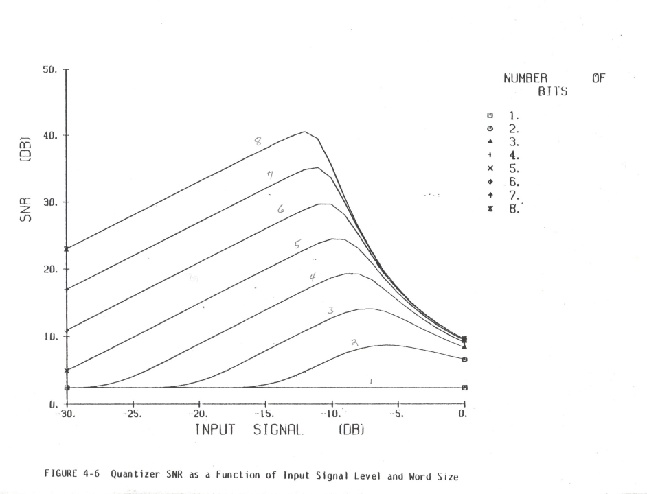
of 10 to 16 bits. I have attached a figure showing plots for A/D
resolutions of 1 to 8 bits that may be of interest. This figure came
from the radar summer course conducted by the University of Michigan.
Early radars tended to use few A/D converter bits.
Jim Abshier
Lester Veenstra
What sort of setup would be needed to reproduce the work on an amateur, open, level?
-------------------------------------------------------------------------------------
(A) First of course, an A/D and digital processing sufficient to look at raw A/D output (ideally) and simultaneously, to do a power spectral density FFT on the output. (Bin widths several times less than notch width)
(B) A noise source of sufficient power to overdrive the A/D after the loss of fixed pads and filters. The critical characteristic here is, of course, end to end flatness over the A/D capability and reasonably high crest factor? Moderate ripple is ok as long as the end to end flatness averages out. A “good” noise source is inherently flat, but in the SARA environment, hay I suggest a string of “wide band 20-30 dB amplifiers, in series, starting with a terminated output. The last stage must have sufficient head room to achieve the desired “crest factor”.
(C) Noise bandwidth filter (Band pass) covering the significant frequency range of the A/D, well down at the Nyquist frequencies. This is used to define in input noise level predictably.
(D) The hard part: A very deep notch filter (Band Stop) , in band of the Noise Bandwidth filter, preferably between ½ and 2/3 Nyquist. As narrow and as deep as money/design expertise can get. As narrow as possible so that the noise power it stops is not a significant part of total band limited noise, but again “as money/design expertise can get”. The depth of the notch should significantly exceed the NPR that the A/D should be capable of achieving based on sample bits.
(E) The easy part, a variable step attenuator.
You can split the band limited, notched, attenuated noise prior to the A/D, in order to measure applied power but that measaurement is not needed or at all that useful in this context of an PTIC vs NPR analysis.
Lester B Veenstra K1YCM MØYCM W8YCM 6Y6Y
452 Stable Ln (HC84 RFD USPS Mail)
Keyser WV 26726
GPS: 39.336826 N 78.982287 W (Google)
GPS: 39.33682 N 78.9823741 W (GPSDO)
Telephones:
Home: +1-304-289-6057
US cell +1-304-790-9192
Jamaica cell: +1-876-456-8898
-----Original Message-----
From: sara...@googlegroups.com [mailto:sara...@googlegroups.com] On Behalf Of Lamar Owen
Sent: Friday, April 30, 2021 4:53 PM
To: sara...@googlegroups.com
Subject: Re: [SARA] Airspy mini & RTLSDR splitter
So, I've snipped just a bit here. I am always willing to learn new
--
--
You received this message because you are subscribed to the Google
Groups "Society of Amateur Radio Astronomers" group.
To post to this group, send email to sara...@googlegroups.com
To unsubscribe from this group, send email to
sara-list-...@googlegroups.com
For more options, visit this group at
http://groups.google.com/group/sara-list?hl=en
---
You received this message because you are subscribed to the Google Groups "Society of Amateur Radio Astronomers" group.
To unsubscribe from this group and stop receiving emails from it, send an email to sara-list+...@googlegroups.com.
To view this discussion on the web visit https://groups.google.com/d/msgid/sara-list/f90a3cfd-acbb-00df-e04a-ee4d7d4e345f%40pari.edu.
Lester Veenstra
Lester B Veenstra K1YCM MØYCM W8YCM 6Y6Y
les...@veenstras.com
452 Stable Ln (HC84 RFD USPS Mail)
Keyser WV 26726
GPS: 39.336826 N 78.982287 W (Google)
GPS: 39.33682 N 78.9823741 W (GPSDO)
Telephones:
Home: +1-304-289-6057
US cell +1-304-790-9192
Jamaica cell: +1-876-456-8898
-----Original Message-----
From: sara...@googlegroups.com [mailto:sara...@googlegroups.com] On Behalf Of Lamar Owen
Sent: Friday, April 30, 2021 4:56 PM
To: sara...@googlegroups.com
Subject: Re: [SARA] Airspy mini & RTLSDR splitter
--
You received this message because you are subscribed to the Google
Groups "Society of Amateur Radio Astronomers" group.
To post to this group, send email to sara...@googlegroups.com
To unsubscribe from this group, send email to
sara-list-...@googlegroups.com
For more options, visit this group at
http://groups.google.com/group/sara-list?hl=en
---
You received this message because you are subscribed to the Google Groups "Society of Amateur Radio Astronomers" group.
To unsubscribe from this group and stop receiving emails from it, send an email to sara-list+...@googlegroups.com.
Lester Veenstra
starting with a terminated input (vice output)
To view this discussion on the web visit https://groups.google.com/d/msgid/sara-list/038301d73e96%24f117bc00%24d3473400%24%40com.
Lamar Owen
> Lamar,
>
> I found the Analog Devices Tutorial that you posted very interesting.
> Thank you for posting it. In the tutorial some plots were given
> showing NPR versus input loading. The plots were for A/D converter
> resolutions of 10 to 16 bits. I have attached a figure showing plots
> for A/D resolutions of 1 to 8 bits that may be of interest. This
> figure came from the radar summer course conducted by the University
> of Michigan. Early radars tended to use few A/D converter bits.