Is this interferometer setup resonable?
83 views
Skip to first unread message

Apeirohedron
May 11, 2022, 9:45:23 AM5/11/22
to Society of Amateur Radio Astronomers
Hi all,
I (finally) got the differential hydrogen-line interferometer I've been working on running in the field. So far, technical difficulties have prevented me from getting any reliable data as of yet, but even so I'm not particularly confident about the data I have gotten; it looks to me like there's some kind of pattern, but I'm worried I'm just trying to find patterns in random noise.
I'll leave an update on this post when I have actual data to report, but regardless I thought it would be worthwhile to describe my setup and see if anyone sees anything wrong with it:
I'm using the differential interferometer (don't know if that's the right term for it) design on the CCERA website, so I have cable runs from my two dishes that plug into two LNAs, physically nearby one another to keep their temperatures the same. The output of the LNAs are split and combined in two different ways; one SDR receives the two signals with the same phase delay, and the other receives one signal 180 degrees out of phase from the other.
- The cables connecting the dishes to the combiner are both 50-foot RG11 coax with F-type connectors, but I have to use adapters to convert them to SMA on both ends.
- The LNAs are both Nooelec SAWbird H1+ Barebones, and I'm powering them using their microUSB port. They're both in a plastic bag and are rubber-banded together to keep their temperatures the same.
- The SDRs are both Nooelec NESDR SMArt XTRs; one of them receives the output of both LNAs through ~15cm SMA cables, since using only connectors put everything under too much stress, and the other is connected to one LNA by a male-to-male SMA connector and the other by a SMA cable cut to half a wavelength (accounting for the velocity factor of the cable) plus the length of the connector inside the hexagonal fasteners.
- I'm using a Raspberry Pi to run the GNU Radio code to read both SDRs and output the data to a file. The flow-graph does the following in order:
- Reads from both SDRs at a sample rate of 2MHz with the correct target frequency, with gain set to manual and IQ offset set to automatic
- Converts the outputs from complex to magnitude squared
- Subtracts the two squared magnitudes
- Moving average over 500k samples (0.25 seconds of integration time)
- Keeps 1 in 500k samples (this makes the moving average mostly pointless; maybe this should be a different number?)
- Outputs the data as floats to a raw binary file using an unbuffered file sink
Thanks,
Aidan

Marcus D. Leech
May 11, 2022, 10:37:50 AM5/11/22
to sara...@googlegroups.com
On 2022-05-11 09:45, Apeirohedron
wrote:
Hi all,
I (finally) got the differential hydrogen-line interferometer I've been working on running in the field. So far, technical difficulties have prevented me from getting any reliable data as of yet, but even so I'm not particularly confident about the data I have gotten; it looks to me like there's some kind of pattern, but I'm worried I'm just trying to find patterns in random noise.
I'll leave an update on this post when I have actual data to report, but regardless I thought it would be worthwhile to describe my setup and see if anyone sees anything wrong with it:
I'm using the differential interferometer (don't know if that's the right term for it) design on the CCERA website, so I have cable runs from my two dishes that plug into two LNAs, physically nearby one another to keep their temperatures the same. The output of the LNAs are split and combined in two different ways; one SDR receives the two signals with the same phase delay, and the other receives one signal 180 degrees out of phase from the other.
How long are the cables between your dishes and the LNAs? How big
are the dishes?
You really really want almost no cable between your feed setup and the LNAs. Temperature matching is nice, but in this case, making that work requires long lengths of
cable between the antenna and the LNA---making your "LNA" not very low-noise.
You really really want almost no cable between your feed setup and the LNAs. Temperature matching is nice, but in this case, making that work requires long lengths of
cable between the antenna and the LNA---making your "LNA" not very low-noise.
- The cables connecting the dishes to the combiner are both 50-foot RG11 coax with F-type connectors, but I have to use adapters to convert them to SMA on both ends.
- The LNAs are both Nooelec SAWbird H1+ Barebones, and I'm powering them using their microUSB port. They're both in a plastic bag and are rubber-banded together to keep their temperatures the same.
- The SDRs are both Nooelec NESDR SMArt XTRs; one of them receives the output of both LNAs through ~15cm SMA cables, since using only connectors put everything under too much stress, and the other is connected to one LNA by a male-to-male SMA connector and the other by a SMA cable cut to half a wavelength (accounting for the velocity factor of the cable) plus the length of the connector inside the hexagonal fasteners.
- I'm using a Raspberry Pi to run the GNU Radio code to read both SDRs and output the data to a file. The flow-graph does the following in order:
- Reads from both SDRs at a sample rate of 2MHz with the correct target frequency, with gain set to manual and IQ offset set to automatic
- Converts the outputs from complex to magnitude squared
- Subtracts the two squared magnitudes
- Moving average over 500k samples (0.25 seconds of integration time)
- Keeps 1 in 500k samples (this makes the moving average mostly pointless; maybe this should be a different number?)
- Outputs the data as floats to a raw binary file using an unbuffered file sink
You need much longer integration time. Several seconds at least.
You might usefully learn how to build yourself an embedded Python block that can take yours samples (integrated and downsampled to perhaps 100Hz) and log them
with "housekeeping" data to a regular ASCII file.
You might usefully learn how to build yourself an embedded Python block that can take yours samples (integrated and downsampled to perhaps 100Hz) and log them
with "housekeeping" data to a regular ASCII file.
I know this is a lot of information, but I was hoping that a few people who know what they're talking about could confirm whether or not this setup has flaws in it. It wouldn't surprise me in the least if there's something I'm doing that makes the entire thing non-functional (honestly, it would kind of explain a lot), so if anyone has time to read through this and give some feedback I would really appreciate it.
Thanks,Aidan
--
--
You received this message because you are subscribed to the Google
Groups "Society of Amateur Radio Astronomers" group.
To post to this group, send email to sara...@googlegroups.com
To unsubscribe from this group, send email to
sara-list-...@googlegroups.com
For more options, visit this group at
http://groups.google.com/group/sara-list?hl=en
---
You received this message because you are subscribed to the Google Groups "Society of Amateur Radio Astronomers" group.
To unsubscribe from this group and stop receiving emails from it, send an email to sara-list+...@googlegroups.com.
To view this discussion on the web visit https://groups.google.com/d/msgid/sara-list/56a432f7-ecfb-4e9c-b35e-07de77f9ada3n%40googlegroups.com.
Apeirohedron
May 11, 2022, 2:26:15 PM5/11/22
to Society of Amateur Radio Astronomers
I totally understand that having the amplifiers before any cables is much better, and while it would be kind of hard to change my setup to work like that I definitely would do that if I was aware it was an option. My understanding was that this type of interferometer only works if the LNAs are at the same exact ambient temperature. My dishes (which are 1.5m homemade mesh prime-focus dishes) are around 80-ish feet and while they are probably pretty close temperature-wise I was under the impression that the small differences in ambient temperature would drown out any real signal. Is it just a tradeoff, where the signal is either noisy or has more severe gain fluctuations, or is it not as much of a problem as I think?
Also, after looking through some of the incomplete data from last afternoon (GNU Radio programs seem to crash sometimes on a Pi because of memory access issues: I'm currently running the Python program from a Bash script that restarts the script when it crashes), I definitely agree that the integration time is too short. I tried averaging the data in Python after the fact, and the data looks a lot better. I'll definitely try increasing the integration time for tomorrow's observation.
As for writing my own Python block, that sounds like a good idea. I've been editing the top_block.py file instead of modifying the .grc file since the editor is slow and I'm more familiar with Python anyway, so I think that would make this way easier. I'll have to see how much I need to downsample for the Pi to keep up with it, though!
Thanks as always,
Aidan
Marcus D. Leech
May 11, 2022, 2:33:08 PM5/11/22
to sara...@googlegroups.com
On 2022-05-11 14:26, Apeirohedron
wrote:
I totally understand that having the amplifiers before any cables is much better, and while it would be kind of hard to change my setup to work like that I definitely would do that if I was aware it was an option. My understanding was that this type of interferometer only works if the LNAs are at the same exact ambient temperature. My dishes (which are 1.5m homemade mesh prime-focus dishes) are around 80-ish feet and while they are probably pretty close temperature-wise I was under the impression that the small differences in ambient temperature would drown out any real signal. Is it just a tradeoff, where the signal is either noisy or has more severe gain fluctuations, or is it not as much of a problem as I think?
If you're using it as a differential *radiometer*, then having
gain-balanced (or, more importantly, gain-derivative-balanced) LNAs
is much more important than in
interferometer mode. You really really don't want 40ft of cable between your feed and the LNAs. Really. Particularly with such small dishes.
interferometer mode. You really really don't want 40ft of cable between your feed and the LNAs. Really. Particularly with such small dishes.
Also, after looking through some of the incomplete data from last afternoon (GNU Radio programs seem to crash sometimes on a Pi because of memory access issues: I'm currently running the Python program from a Bash script that restarts the script when it crashes), I definitely agree that the integration time is too short. I tried averaging the data in Python after the fact, and the data looks a lot better. I'll definitely try increasing the integration time for tomorrow's observation.
Which model of Pi? I've run fairly-sophisticated flow-graphs on an
Odroid XU4Q with only 2G of memory, and never had memory issues.
But at 1G, I could see that
happening. "Modern" Linuxes tend NOT to page, since main memory is generally (not always) plentiful. On embedded-class systems, they use something called
the "OOM Killer" to kill memory-hog processes.
happening. "Modern" Linuxes tend NOT to page, since main memory is generally (not always) plentiful. On embedded-class systems, they use something called
the "OOM Killer" to kill memory-hog processes.
As for writing my own Python block, that sounds like a good idea. I've been editing the top_block.py file instead of modifying the .grc file since the editor is slow and I'm more familiar with Python anyway, so I think that would make this way easier. I'll have to see how much I need to downsample for the Pi to keep up with it, though!
Thanks as always,Aidan
I generally don't do *development* on the target platform if it's an
embedded type system like a Pi. I make sure I have a compatible
version of GR on an x86 laptop or
desktop, do the development there, and then ship the files over to the embedded system.
desktop, do the development there, and then ship the files over to the embedded system.
To view this discussion on the web visit https://groups.google.com/d/msgid/sara-list/55b3a848-14e9-477b-9b6b-060399029730n%40googlegroups.com.

Alex P
May 11, 2022, 4:28:15 PM5/11/22
to Society of Amateur Radio Astronomers
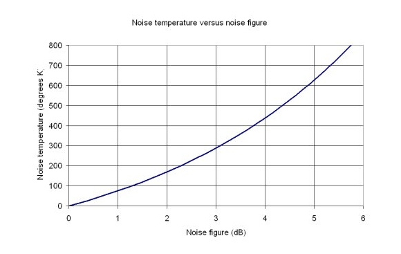
For an indication of performance vs noise, I suggest reading this
( and see attached chart )
For RG-11, 50 ft length, loss at 1.4GHz = 2.7 to 3.3 dB ( depending on reference ) + adapters : that has a significant impact on your system performance .
Alex KK4VB

Jim Abshier
May 11, 2022, 5:01:33 PM5/11/22
to sara...@googlegroups.com
Aiden,
I certainly agree with those who recommend putting the LNAs at the
antennas. As for the drift problem, in the add-and-subtract (or
differential) interferometer system, the noises from the LNAs are added
in one channel and subtracted in the other channel so any power drift in
either or both LNAs should result in the same power change in the sum
and difference channels. Subtracting after power detection should cancel
the effect. What is important is balancing the gain in the sum and
difference channels after the combiners. Differential gain drifts there
will cause baseline drift in the output. For this part of the system,
you are at the mercy of the RTL SDRs.
Jim Abshier
On 5/11/22 2:26 PM, Apeirohedron wrote:
>
> I totally understand that having the amplifiers before any cables is
> much better, and while it would be kind of hard to change my setup to
> work like that I definitely would do that if I was aware it was an
> option. My understanding was that this type of interferometer
> _only_ works if the LNAs are at the same exact ambient temperature. My
>> * The cables connecting the dishes to the combiner are both
>> hexagonal fasteners.
>> * I'm using a Raspberry Pi to run the GNU Radio code to read
>> o Subtracts the two squared magnitudes
>> o Moving average over 500k samples (0.25 seconds of
>> integration time)
>> o Keeps 1 in 500k samples (this makes the moving average
>> <https://groups.google.com/d/msgid/sara-list/56a432f7-ecfb-4e9c-b35e-07de77f9ada3n%40googlegroups.com?utm_medium=email&utm_source=footer>.
> <https://groups.google.com/d/msgid/sara-list/55b3a848-14e9-477b-9b6b-060399029730n%40googlegroups.com?utm_medium=email&utm_source=footer>.
I certainly agree with those who recommend putting the LNAs at the
antennas. As for the drift problem, in the add-and-subtract (or
differential) interferometer system, the noises from the LNAs are added
in one channel and subtracted in the other channel so any power drift in
either or both LNAs should result in the same power change in the sum
and difference channels. Subtracting after power detection should cancel
the effect. What is important is balancing the gain in the sum and
difference channels after the combiners. Differential gain drifts there
will cause baseline drift in the output. For this part of the system,
you are at the mercy of the RTL SDRs.
Jim Abshier
On 5/11/22 2:26 PM, Apeirohedron wrote:
>
> I totally understand that having the amplifiers before any cables is
> much better, and while it would be kind of hard to change my setup to
> work like that I definitely would do that if I was aware it was an
> option. My understanding was that this type of interferometer
>> 50-foot RG11 coax with F-type connectors, but I have to use
>> adapters to convert them to SMA on both ends.
>> * The LNAs are both Nooelec SAWbird H1+ Barebones, and I'm
>> adapters to convert them to SMA on both ends.
>> powering them using their microUSB port. They're both in a
>> plastic bag and are rubber-banded together to keep their
>> temperatures the same.
>> * The SDRs are both Nooelec NESDR SMArt XTRs; one of them
>> plastic bag and are rubber-banded together to keep their
>> temperatures the same.
>> receives the output of both LNAs through ~15cm SMA cables,
>> since using only connectors put everything under too much
>> stress, and the other is connected to one LNA by a
>> male-to-male SMA connector and the other by a SMA cable cut
>> to half a wavelength (accounting for the velocity factor of
>> the cable) plus the length of the connector _inside_ the
>> since using only connectors put everything under too much
>> stress, and the other is connected to one LNA by a
>> male-to-male SMA connector and the other by a SMA cable cut
>> to half a wavelength (accounting for the velocity factor of
>> hexagonal fasteners.
>> * I'm using a Raspberry Pi to run the GNU Radio code to read
>> both SDRs and output the data to a file. The flow-graph does
>> the following in order:
>> o Reads from both SDRs at a sample rate of 2MHz with the
>> the following in order:
>> correct target frequency, with gain set to manual and IQ
>> offset set to automatic
>> o Converts the outputs from complex to magnitude squared
>> offset set to automatic
>> o Subtracts the two squared magnitudes
>> o Moving average over 500k samples (0.25 seconds of
>> integration time)
>> o Keeps 1 in 500k samples (this makes the moving average
>> mostly pointless; maybe this should be a different number?)
>> o Outputs the data as floats to a raw binary file using an
>
> --
> --
> You received this message because you are subscribed to the Google
> Groups "Society of Amateur Radio Astronomers" group.
> To post to this group, send email to sara...@googlegroups.com
> To unsubscribe from this group, send email to
> sara-list-...@googlegroups.com
> For more options, visit this group at
> http://groups.google.com/group/sara-list?hl=en
> ---
> You received this message because you are subscribed to the Google
> Groups "Society of Amateur Radio Astronomers" group.
> To unsubscribe from this group and stop receiving emails from it, send
> an email to sara-list+...@googlegroups.com
> <mailto:sara-list+...@googlegroups.com>.
> --
> --
> You received this message because you are subscribed to the Google
> Groups "Society of Amateur Radio Astronomers" group.
> To post to this group, send email to sara...@googlegroups.com
> To unsubscribe from this group, send email to
> sara-list-...@googlegroups.com
> For more options, visit this group at
> http://groups.google.com/group/sara-list?hl=en
> ---
> You received this message because you are subscribed to the Google
> Groups "Society of Amateur Radio Astronomers" group.
> To unsubscribe from this group and stop receiving emails from it, send
> an email to sara-list+...@googlegroups.com
> To view this discussion on the web visit
> https://groups.google.com/d/msgid/sara-list/55b3a848-14e9-477b-9b6b-060399029730n%40googlegroups.com
> <https://groups.google.com/d/msgid/sara-list/55b3a848-14e9-477b-9b6b-060399029730n%40googlegroups.com?utm_medium=email&utm_source=footer>.
Marcus D. Leech
May 11, 2022, 7:29:38 PM5/11/22
to sara...@googlegroups.com
On 2022-05-11 16:28, 'Alex P' via
Society of Amateur Radio Astronomers wrote:
For an indication of performance vs noise, I suggest reading this
( and see attached chart )
For RG-11, 50 ft length, loss at 1.4GHz = 2.7 to 3.3 dB ( depending on reference ) + adapters : that has a significant impact on your system performance .
Alex KK4VB
If one conservatively assumes that the combined insertion loss and
inherent noise figure combine to about 5dB, then the Tsys will be
somewhere around 900K or
thereabouts--add in spillover, if any, and probably 20K on a small dish.
900K isn't insurmountable, just "unpleasant". But combine that with the small dish size, and limited bandwidth, and things don't look that wonderful.
With 1.5m antennas the beam-width will be about 10deg, assuming no under-illumination. That means the sun will occupy about 1/400th of the beam. The Sun
is a pretty-good "test" object. Let's call the brightness temperature of the Sun at 21cm 100,000K. So, 100,000/400 == 250K. Since you're using single polarization,
your receivers will *see* half of that, or about 125K. Now, the "cold" sky at 21cm varies over a range of about 10K to about 90K. For purposes of analysis, let's call
the "cold" sky 50K. So, as a *radiometer*, a single-dish + receiver should "see" a response of about:
Tsys = 920
Tsun = 125
Tcold = 50
Tsys+Tsun / Tsys+Tcold
(920+125) / (920+50)
Or about 0.3dB change due to the Sun
0.3dB is "enough" but kinda sad for the Sun. For other objects, the Tant due to that object passing through is likely to be 1K or less.
You can see how these numbers get much nicer once your Tsys dives below about 150K....
Now, Cass. A has an apparent size of about 5 arcmin, or about 1/14000th of your beam. The overwhelming fraction of your single-antenna input will be
galactic background, again, call it 50K. Cass. A at L-band is about 2500Jy, or about 2500K brightness temperature. So, 2500K / 14000 = 0.18K.
That's not a lot when set against a Tsys of 920K. But with very-long integration times, and an interferometer at least partially removing the large-scale
backgrounds, you might be able to "see" Cass. A with your setup, particularly if you lower Tsys considerably.
- The cables connecting the dishes to the combiner are both 50-foot RG11 coax with F-type connectors, but I have to use adapters to convert them to SMA on both ends.
- The LNAs are both Nooelec SAWbird H1+ Barebones, and I'm powering them using their microUSB port. They're both in a plastic bag and are rubber-banded together to keep their temperatures the same.
- The SDRs are both Nooelec NESDR SMArt XTRs; one of them receives the output of both LNAs through ~15cm SMA cables, since using only connectors put everything under too much stress, and the other is connected to one LNA by a male-to-male SMA connector and the other by a SMA cable cut to half a wavelength (accounting for the velocity factor of the cable) plus the length of the connector inside the hexagonal fasteners.
--
--
You received this message because you are subscribed to the Google
Groups "Society of Amateur Radio Astronomers" group.
To post to this group, send email to sara...@googlegroups.com
To unsubscribe from this group, send email to
sara-list-...@googlegroups.com
For more options, visit this group at
http://groups.google.com/group/sara-list?hl=en
---
You received this message because you are subscribed to the Google Groups "Society of Amateur Radio Astronomers" group.
To unsubscribe from this group and stop receiving emails from it, send an email to sara-list+...@googlegroups.com.
To view this discussion on the web visit https://groups.google.com/d/msgid/sara-list/245514b1-4899-478e-a8b9-35acca6a7290n%40googlegroups.com.
Apeirohedron
May 12, 2022, 8:27:26 AM5/12/22
to Society of Amateur Radio Astronomers
Yeah, 0.18K doesn't sound like much. Possibly a dumb question, but what can I actually do to reduce the system temperature? Is it just 'have better components'? Is that calculation for my current setup with the amplifiers before the cable run, or will that not make a difference?
Also, related question: I'm trying to put the amplifiers before the cable runs, but I've found that they're producing a lot of DC voltage which I hadn't considered previously (I've checked and the SDRs and LNAs are all undamaged as far as I can tell). From other posts, it seems like I'm supposed to have a DC block after each LNA. Is that the correct solution? I don't want to kill any of my equipment.
Thanks,
Aidan
b alex pettit jr
May 12, 2022, 8:44:14 AM5/12/22
to sara...@googlegroups.com
Hi Aidan,
Look at this info on the Friis Equation
Noise figure (NF) and noise factor (F) are measures of degradation of the signal-to-noise ratio (SNR), caused by components in a signal chain.
It is a number by which the performance of an amplifier or a radio
receiver can be specified, with lower values indicating better
performance.
Linear passive devices have noise figure equal to their loss. Expressed in dB, the NF is equal to -S21(dB).
Something with one dB loss
has one dB noise figure
So, if the 50 ft of RG11 has 3 dB atten and each of the 4 connectors ( F and F<>SMA adapters ) have 0.25 dB loss, you have 4 dB of loss =
4dB of Noise 'temperature' added to the system due to having the Cable before the LNA.
What can I actually do to reduce the system temperature? Move the LNA to the antenna feed_point before the 50ft of cable
Self powering the SAWBird also puts 5V on the Output . DC Blocks will not hurt ... depends on the SDR if that is an issue or not.
Alex KK4VB
Marcus D. Leech
May 12, 2022, 9:12:49 AM5/12/22
to sara...@googlegroups.com
On 2022-05-12 08:44, 'b alex pettit jr'
via Society of Amateur Radio Astronomers wrote:
Hi Aidan,
Look at this info on the Friis Equation
Noise figure (NF) and noise factor (F) are measures of degradation of the signal-to-noise ratio (SNR), caused by components in a signal chain.It is a number by which the performance of an amplifier or a radio receiver can be specified, with lower values indicating better performance.Linear passive devices have noise figure equal to their loss.
Expressed in dB, the NF is equal to -S21(dB).
Something with one dB loss has one dB noise figure
So, if the 50 ft of RG11 has 3 dB atten and each of the 4 connectors ( F and F<>SMA adapters ) have 0.25 dB loss, you have 4 dB of loss =4dB of Noise 'temperature' added to the system due to having the Cable before the LNA.
What can I actually do to reduce the system temperature? Move the LNA to the antenna feed_point before the 50ft of cable
Self powering the SAWBird also puts 5V on the Output . DC Blocks will not hurt ... depends on the SDR if that is an issue or not.
I'm unaware of any SDRs that DO NOT have a DC-block on the input,
but putting one on the output of
the LNA is just good hygiene if you know that there's DC coming out of it, and you don't want it there.
Also, "data sheet" loss figures are almost always optimistic for coax and connectors. So I "do the math" and
add about 1dB due to the "fibbing factor". One could actually measure it to be sure, but that rule-of-thumb
has generally been close to the "truth" for me.
Alex KK4VB
On Thursday, May 12, 2022, 08:27:29 AM EDT, Apeirohedron <apeirohe...@gmail.com> wrote:
Yeah, 0.18K doesn't sound like much. Possibly a dumb question, but what can I actually do to reduce the system temperature? Is it just 'have better components'? Is that calculation for my current setup with the amplifiers before the cable run, or will that not make a difference?
Also, related question: I'm trying to put the amplifiers before the cable runs, but I've found that they're producing a lot of DC voltage which I hadn't considered previously (I've checked and the SDRs and LNAs are all undamaged as far as I can tell). From other posts, it seems like I'm supposed to have a DC block after each LNA. Is that the correct solution? I don't want to kill any of my equipment.
Thanks,Aidan
--
--
You received this message because you are subscribed to the Google
Groups "Society of Amateur Radio Astronomers" group.
To post to this group, send email to sara...@googlegroups.com
To unsubscribe from this group, send email to
sara-list-...@googlegroups.com
For more options, visit this group at
http://groups.google.com/group/sara-list?hl=en
---
You received this message because you are subscribed to the Google Groups "Society of Amateur Radio Astronomers" group.
To unsubscribe from this group and stop receiving emails from it, send an email to sara-list+...@googlegroups.com.
To view this discussion on the web visit https://groups.google.com/d/msgid/sara-list/459834154.1391485.1652359476814%40mail.yahoo.com.
b alex pettit jr
May 12, 2022, 9:13:25 AM5/12/22
to 'b alex pettit jr' via Society of Amateur Radio Astronomers
And, although the equation shows that noise in the later stages is reduced by the gain of the device and preceding stages,
it is easier to 'visualize' that the initial noise sources are Amplified by the Later Stages.

" The First Noise is the Worst Noise "
AP
Marcus D. Leech
May 12, 2022, 9:19:30 AM5/12/22
to sara...@googlegroups.com
On 2022-05-12 09:13, 'b alex pettit jr'
via Society of Amateur Radio Astronomers wrote:
And, although the equation shows that noise in the later stages is reduced by the gain of the device and preceding stages,it is easier to 'visualize' that the initial noise sources are Amplified by the Later Stages.
Indeed, once you have 30+dB of low-noise gain "up front", you can
have loss after it and it doesn't affect
overall Tsys more than a tiny amount. We use RG6 because it's cheap, parts for it are literally available
at the local hardware store, and since we always have our low-noise amplifiers/converters "right up front",
the loss in the cabling system is less of an issue. The shielding of more-expensive cables is either the
same or slightly-worse than RG6Q. The other thing to consider is the the apparent gain drift due to
temperature changes in the cables--it will be better with lower-loss cables, but not so much that it's
"worth it" in my opinion--you'll always need *some* method to compensate for that, and an interferometer
nicely takes care of that :) [yes, the fringe magnitudes will change a bit, but you cannot be 'fooled' the way
you can with a single-dish radiometer system].
" The First Noise is the Worst Noise "
AP
--
--
You received this message because you are subscribed to the Google
Groups "Society of Amateur Radio Astronomers" group.
To post to this group, send email to sara...@googlegroups.com
To unsubscribe from this group, send email to
sara-list-...@googlegroups.com
For more options, visit this group at
http://groups.google.com/group/sara-list?hl=en
---
You received this message because you are subscribed to the Google Groups "Society of Amateur Radio Astronomers" group.
To unsubscribe from this group and stop receiving emails from it, send an email to sara-list+...@googlegroups.com.
To view this discussion on the web visit https://groups.google.com/d/msgid/sara-list/413491035.1391906.1652361201485%40mail.yahoo.com.
Apeirohedron
May 12, 2022, 9:30:20 AM5/12/22
to Society of Amateur Radio Astronomers
Quick question then: by 'good hygiene', do you mean that I would be taking a risk by not adding DC blocks or that it's general good practice but not necessarily an issue in this situation? I definitely do want to do things correctly as much as possible, but I'm under time pressure and don't want to lose observation time waiting for ordered parts to arrive if not using them is safe.
- Aidan

fasleitung3
May 13, 2022, 5:16:33 AM5/13/22
to sara...@googlegroups.com
I'm unaware of any SDRs that DO NOT have a DC-block on the input
The ADALM-Pluto does not have a DC block, I learned this the hard way.....
Wolfgang
Marcus D. Leech
May 13, 2022, 12:31:03 PM5/13/22
to sara...@googlegroups.com
Good to know. Such a simple thing, and yet it gets missed by
designers...
--
--
You received this message because you are subscribed to the Google
Groups "Society of Amateur Radio Astronomers" group.
To post to this group, send email to sara...@googlegroups.com
To unsubscribe from this group, send email to
sara-list-...@googlegroups.com
For more options, visit this group at
http://groups.google.com/group/sara-list?hl=en
---
You received this message because you are subscribed to the Google Groups "Society of Amateur Radio Astronomers" group.
To unsubscribe from this group and stop receiving emails from it, send an email to sara-list+...@googlegroups.com.
To view this discussion on the web visit https://groups.google.com/d/msgid/sara-list/27a31a3cf9fce0553b2ed19bf30946837181d718.camel%40googlemail.com.
Marcus D. Leech
May 13, 2022, 3:10:42 PM5/13/22
to sara...@googlegroups.com
On 2022-05-12 08:27, Apeirohedron
wrote:
Yeah, 0.18K doesn't sound like much. Possibly a dumb question, but what can I actually do to reduce the system temperature? Is it just 'have better components'? Is that calculation for my current setup with the amplifiers before the cable run, or will that not make a difference?
Move your LNAs right up to the feeds. That's the main thing you can
do.
Also, related question: I'm trying to put the amplifiers before the cable runs, but I've found that they're producing a lot of DC voltage which I hadn't considered previously (I've checked and the SDRs and LNAs are all undamaged as far as I can tell). From other posts, it seems like I'm supposed to have a DC block after each LNA. Is that the correct solution? I don't want to kill any of my equipment.
Yes, if you're powering your LNAs from the micro-usb port, because
they have a multiple-methods strategy for getting DC power, if you
put DC power in at one point, it will
show up at the other points. Put in a DC block on the output of the LNAs, because "up the coax" is one of the ways they get DC power.
show up at the other points. Put in a DC block on the output of the LNAs, because "up the coax" is one of the ways they get DC power.
To view this discussion on the web visit https://groups.google.com/d/msgid/sara-list/ad5f5322-55f5-4a24-8cc7-c3494a80f817n%40googlegroups.com.
Marcus D. Leech
May 13, 2022, 3:10:42 PM5/13/22
to sara...@googlegroups.com
On 2022-05-12 09:30, Apeirohedron
wrote:
Quick question then: by 'good hygiene', do you mean that I would be taking a risk by not adding DC blocks or that it's general good practice but not necessarily an issue in this situation? I definitely do want to do things correctly as much as possible, but I'm under time pressure and don't want to lose observation time waiting for ordered parts to arrive if not using them is safe.
- Aidan
I think you're using RTLSDR which have DC blocks on the input. You
could confirm with NooElec technical support.
If this is a school project, then, yeah, I totally understand "time pressure". But, in the general case, those objects will still be there next week, and
long after we're all dust :) :)
If this is a school project, then, yeah, I totally understand "time pressure". But, in the general case, those objects will still be there next week, and
long after we're all dust :) :)
To view this discussion on the web visit https://groups.google.com/d/msgid/sara-list/b0c0141f-aefc-4ae2-b571-1b365e2f3d1en%40googlegroups.com.
Reply all
Reply to author
Forward
0 new messages