Understanding triq.org/pdv analyzer settings
319 views
Skip to first unread message

David Todd
Mar 2, 2022, 3:25:43 PM3/2/22
to rtl_433
I'm hoping that someone can help me understand how to correctly set triq.org/pdv Analyzer settings for PPM.
I have an Acurite 609 remote, which i sat 10cm from the RTL-SDR antenna while I ran rtl_433. I collected data until I saw two sets of transmissions from the 609 (5 packets per transmission). I converted to an .ook file with rtl_433 -r a609.cu8 -W a609.ook. I dropped the .ook file into triq's pdv and scanned to make sure I had the transmissions from the 609 (they were at the end of the OOK section). Then I edited the .OOK file to remove all the extraneous signals and dropped the edited .ook file into triq/pdv again.
I know the ID, temp, and humidity at the time of the samplings from the remote's monitor, and translating those to the message format of the 609 (using rtl_433's acurite.c to learn the format), the packet should be A4A0C120cc (cc=checksum). I also know that acurite.c says that shorts are 1000µs, longs are 2000µs, gaps are 3000µs, and resets are 10000µs.
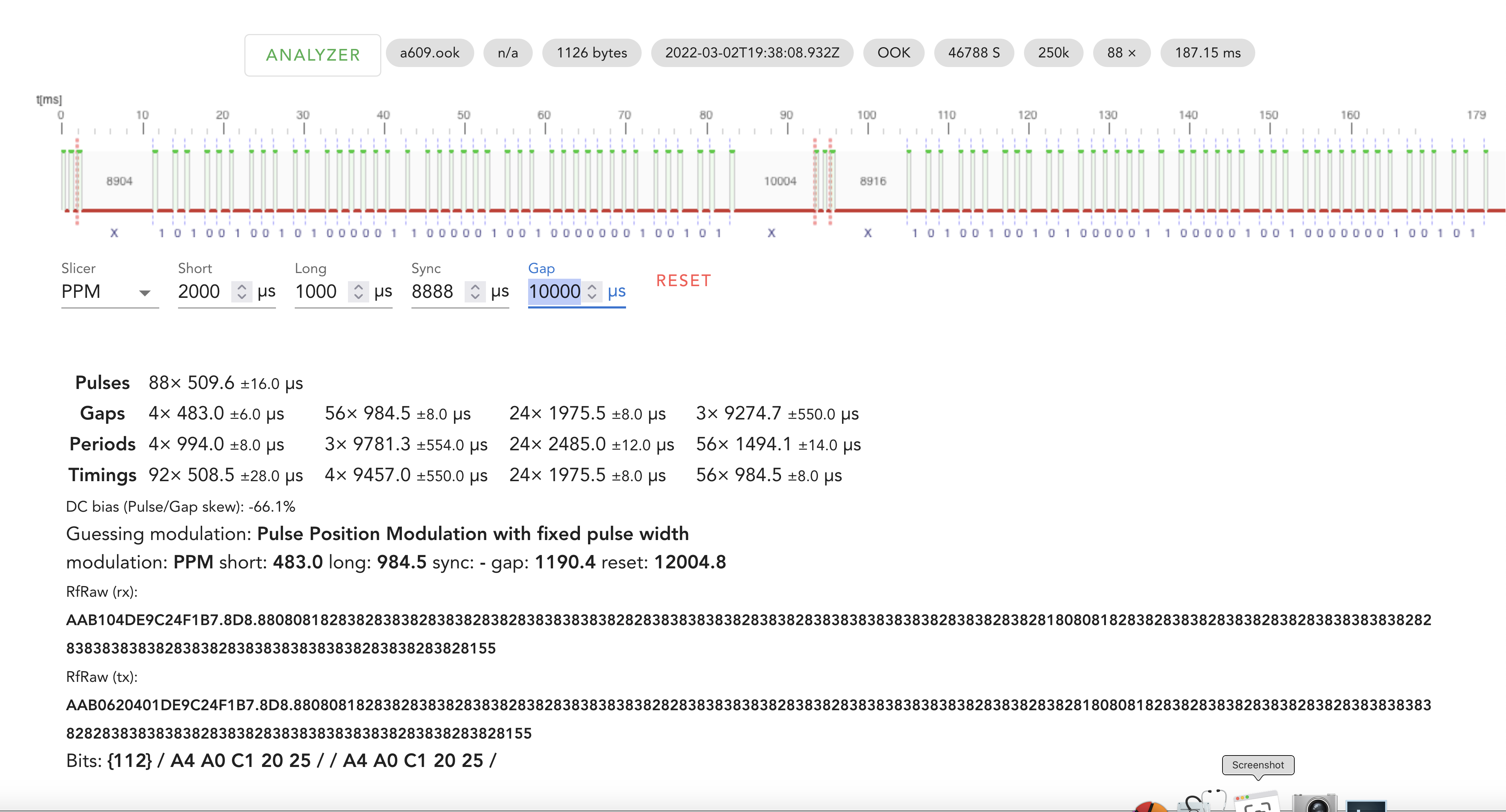
With that .ook file in view, if I set the Analyzer with 2000 for short and 1000 for long, 8888 (or 10000) for sync and 10000 for gap, Analyzer correctly say that I have two packets of A4A0C120cc.
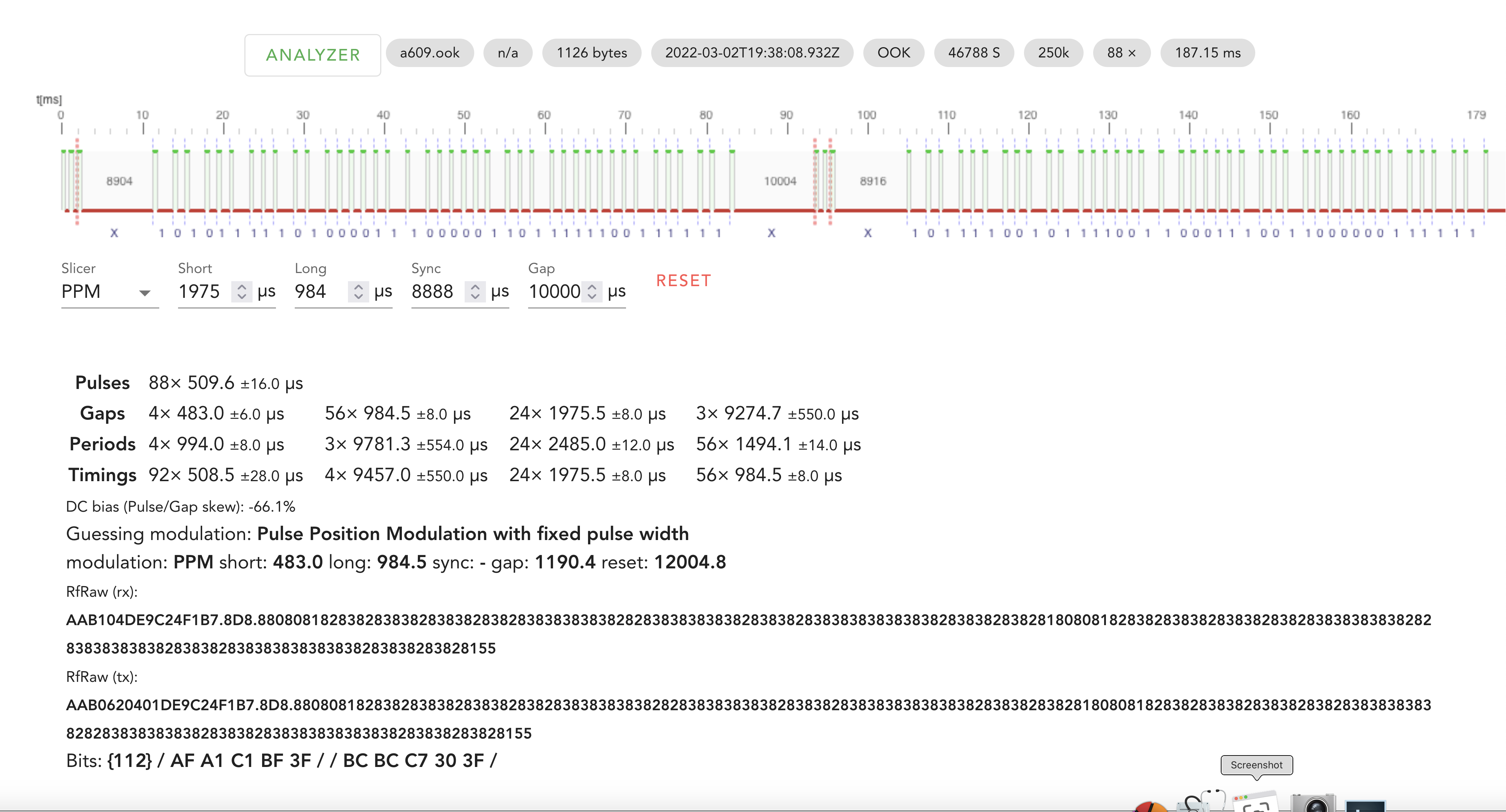
But if I look at the Analyzer's gap/period/timing analysis, I see that it might be better to use 1975 for short, 984 for long, 8888 for sync, and 10000 for gap. But if I use those, the analysis comes out incorrectly (two packets with different values).
If I didn't know from rtl_433's acurite.c what the timings should be -- for example, if I were analyzing the transmissions from a new device -- I would have expected to use the Analyzer's timings to try to understand the pattern (for example, reversing the values for long and short), and I wouldn't have gotten anywhere near to the actual packet values.
I've apparently misunderstood how to use the Analyzer's data to help decode packets. Could someone explain how I would have used the Analyzer's pulse/gap/period analysis to help with the PPM decoding of the packet bits? Or should I just visually examine the pulse train and base my Analyzer settings on what I see.
I've attached two .png files showing the two analyses with the pulse train.
Thanks in advance for any advice you can offer.

Christian Z.
Mar 2, 2022, 3:44:42 PM3/2/22
to rtl_433
Short needs to be shorter than Long, from the pulse stats you can see they should be 500 and 1000. The exact values don't matter to much the PPM slicer will decide by a threshold in the middle between Short and Long.
There are no sync pulses, ignore that option.
Gap is means "any gap longer than this breaks into a new packet", you want more than 2000 here, say 2500.
But from eyeballing the screenshot the A4A0C12025 looks correct.
David Todd
Mar 2, 2022, 5:47:26 PM3/2/22
to rtl_433
Christian,
If I use the parameters in the "Correct" png, the bit pattern at the bottom of the screen is correct, and the formatting suggests that it's seeing two packets, which is also correct. (SHORT=2000, LONG=1000, SYNC=8888, GAP=10000, which yields Bits: {112} / A4 A0 C1 20 25 / / A4 A0 C1 20 25 /)
And I know that to be correct because I created the same bit pattern from the monitor data. And I know that there are two packets in that sample.
The SYNC pulse is the 8904µs low signal after the initial three pulses, and apparently it determines how the Analyzer distinguishes two packets rather than one in that transmission. So it's not required but it's helpful. If I drop SYNC, I get the two messages as one packet. Not as helpful as seeing that there were two repeated packets in that single transmission.
If I use short=1000 long=2000, the bit pattern is the 1's complement of the correct pattern: Bits: {112} / 5B 5F 3E DF DA / / 5B 5F 3E DF DA /
And if I set SYNC to 0, it's reported as one long packet rather than two, again.
So the most accurate settings are the ones I used for "CORRECT" (discovered by switching the parameters around).
If I were analyzing a real, unknown device, those are the settings I'd want to be using because they'd give me the most accurate picture of the data being transmitted.
But they're not what I'd guess by looking at the timing analysis -- LONG and SHORT reversed, for example.
So maybe there's no simple way to look at the timing analysis and set the PPM parameters to immediately get the packet information: maybe you just have to apply the parameters in different ways until you get something that makes sense. But I was hoping there was a more direct process for the decoding.
I've attached the .cu8 file if you want to explore it. Maybe there's something else I'm doing wrong -- I'm completely new at this.
Thanks for thinking about it!
David Todd
Mar 2, 2022, 9:11:09 PM3/2/22
to rtl_433
Christian,
I apologize ... that was a long response for what should have been a quick message.
You're absolutely right: I would have expected to use the parameters off the Analysis timings to set up the PPM parameters. But I know what the answer should be, and those parameters don't give me that result.
So how would I translate the Analysis parameters into Analysis PPM parameters to get the correct result?
David
On Wednesday, March 2, 2022 at 3:44:42 PM UTC-5 Christian Z. wrote:
Christian Z.
Mar 3, 2022, 2:07:30 AM3/3/22
to rtl_433
> bottom of the screen is correct (SHORT=2000, LONG=1000
Using a short longer than long is not expected and will produce weird behaviour generally.
> I know that there are two packets in that sample.
Yes, we can see that in the display.
> The SYNC pulse is the 8904µs low signal
In general terms a pulse is high-level, a gap low-level. For FSK the terms mark and space are also used.
A Sync would be a third length of pulse in e.g. PWM.
> If I drop SYNC, I get the two messages as one packet.
This seems to be a bug in the slicer, the "/" symbol is missing in the output.
> If I use short=1000 long=2000, the bit pattern is the 1's complement of the correct pattern
We’ll usually assign high levels or high frequency (fast) level changes a bit value of 1, low levels or low frequency (slow) level changes a bit value of 0. This not a commonly accepted convention though and needs to be figured out for each protocol.
You just need to invert the displayed bits afterwards, it's not generally something the slicer can deliver.
I might need to add an option for that.
> So maybe there's no simple way to look at the timing analysis and set the PPM parameters to immediately get the packet information
> I've attached the .cu8 file if you want to explore it.
I didn't pick up there where two different files and timings in your post.
Let's look at the file:
- Pulses 88× 509 µs
This clearly is PPM, ignore this width.
- Gaps 4× 483 µs 56× 984 µs 24× 1975 µs 3× 9274 µs
The 483 gaps are not the ones you are looking for (too low count), neither are the 9274 ones, they are at the packet boundaries. Ignore them.
The 984 and 1975 carry the data, use them for short and long.
Use something wider than long and shorter than the 9274 to split packets, the Reset or Gap setting, say 2500.
I'll look into the issue with the missing packet separator and if "invert" can be added.
Christian Z.
Mar 3, 2022, 2:15:59 AM3/3/22
to rtl_433
Oh, and if at all the sync should be the 483, say 500, to recognize the very short gaps at the start. This will break into a new packet on each sync. rtl_433 does support this for PPM.
It is in fact, as you understood, the third symbol, i.e. gaps of ~500->sync ~1000->short ~2000->long, much longer -> new packet.
David Todd
Mar 3, 2022, 9:05:14 AM3/3/22
to rtl_433
Christian,
First, let me say that rtl_433 and the triq/pdv site are astounding pieces of work. Congratulations to those of your working on those: beautiful work, and very helpful.
Second, thanks for your analysis above. That suggests how I should be looking at these in the future. I think I'm having trouble with the terminology, so I was not quite sure how to use the timings analysis to inform the bit-pattern analysis. I knew that, in this case, it was the gap timings that carried the data. Looking at the gap/period/timing analysis, I'd have thought that SHORT=984 and LONG=1975 were the right settings, with the SYNC gap = 8888 and the inter-packet GAP = 10000. And, in fact, those settings almost work -- the bit pattern analysis sees two packets, but the bit values are reversed and as a result the analyzer's bit pattern is the 1's comp of the actual packet value -- 5B 5F 3E DF DA rather than A4 A0 C1 20 25. So SHORT==>0 and LONG==>1 in the Acurite 609 signaling. I got to the settings in my "CORRECT" png by switching parameters around until I got the result I knew I should see, but that's not the way to do it in the future if I don't already know what the answer is. 😉
I suppose that, in general, given just the pattern of long and short gaps, they could be assigned 0/1 or 1/0 values. So as I look at these in the future, I have to keep that in mind. There may be a convention that LONG==>0 and SHORT==>1, but it's not a universal standard.
So I think that what I learned in this case, for a PPM analysis of the Acurite 609 signaling, is:
- Load the .ook file into triq.org/pdv to see the pulse trains. Edit the .ook file to isolate just a few of the OOK pulse trains for the device you're investigating. Load that edited file into triq.org/pdv, and you now have a timing analysis for just the device you're investigating.
- Look at the pulse train; note any sync bits and gaps between them and at the gap between the sync pulse(s) and the first data pulses; use the timing of that gap between sync pulses and first data pulse as the value for SYNC
- Note the gap between packets as the value for the timing of the GAP field
- Look at the gap/period/timing analysis and look for largest counts of the short and long gaps: those are probably carrying the data. Use those timings as the values of SHORT and LONG in the analyzer
- Look at the resulting bit pattern at the bottom of the analysis. It should reflect the number of packets you have from the visual inspection of the pulse train at the top. BUT, the actual data packets may be 1's complement of the bit pattern reported, as the encoding may have chosen to use SHORT/LONG as 0/1 or 1/0.
Again, thanks for your help: this is exactly what I needed.
David
Christian Z.
Mar 3, 2022, 9:24:34 AM3/3/22
to rtl_433
A good summary. Also note that when looking at hex nibbles there is generally no inherent alignment from pulses to bits, you might want to look at the hex with 1 to 3 bits shifted. So 8 possible hex representations, 0-3 bits shift and inverted.
Playing with the codes in BitBench might help for a quick inspection. https://triq.net/bitbench
Though usually not the case with PPM other pulse codes like PWM and very common with PCM (NRZ) there might be another coding on top, e.g. Manchester, Differential Manchester, NRZI, CMI/AMI, Bit-Stuffing, Whitening, ...
I'm in the process of writing an introduction to all the common ones, a first overview is currently at https://triq.org/rtl_433/PULSE_FORMATS.html
A description of the slicer parameters will follow.
David Todd
Mar 3, 2022, 10:27:59 AM3/3/22
to rtl_433
On Thursday, March 3, 2022 at 9:24:34 AM UTC-5 Christian Z. wrote:
I'm in the process of writing an introduction to all the common ones, a first overview is currently at https://triq.org/rtl_433/PULSE_FORMATS.htmlA description of the slicer parameters will follow.
I read this for the first time yesterday, and it was incredibly helpful. Recommended reading for anyone trying to figure this stuff out. Your comment in there "We’ll usually assign high levels or high frequency (fast) level changes a bit value of 1,
low levels or low frequency (slow) level changes a bit value of 0.
This not a commonly accepted convention though and needs to be figured out for each protocol." seems especially helpful in retrospect. That was exactly what was causing me so much trouble.
Reply all
Reply to author
Forward
0 new messages