Skip to first unread message

theFabFor
Dec 31, 2014, 6:35:35 PM12/31/14
to ros-by-...@googlegroups.com
I've built a differential drive robotic base and am attempting to control it using ros arduino bridge but am having an issue I can't seem to fix. When using the arduino serial connection to control it, and the encoder count is set to 0, a command of m 50 50 will result in an encoder count of ~3500. An associated, I'm assuming, issue is experienced when running the robot via ros topic pub cmd_vel. This command $ rostopic pub -r 10 /cmd_vel geometry_msgs/Twist '{linear: {x: 0.1, y: 0, z: 0}, angular: {x: 0, y: 0, z: 0}}' will send the wheels spinning rapidly to full speed, sometimes stopping and changing directions randomly. Any suggestions would be greatly appreciated.
Thanks in advance

Alex McClung
Jan 1, 2015, 9:09:38 PM1/1/15
to ros-by-...@googlegroups.com
I built a similar robot platform with unsupported hardware (larger motors, different motor drivers, more encoder counts/rev and encoder board etc.) and had to modify ROS Arduino Bridge firmware to support them. It took a few hours of tuning different PID parameters to stop getting the same sort of erratic behaviour you are describing.
ROS Arduino Bridge uses two PID controllers; one for the velocity of each wheel on the robot, which (when tuned properly) it keeps the motor spinning at the desired speed, it calculates the velocity (using the change in encoder position over time), if the calculated velocity is slower than what we asked for; it drives the motor faster, or if its too fast; it slows the motor down.
The PID parameters (Kp, Ki, Kd, Ko) are set in arduino_params.yaml and sent to the Arduino when the ROS node is started (they can also be configured directly on the arduino in diff_controller.h or through the serial terminal). Basically the larger the numbers; the more the PID controller tries to compensate for the wheel speed giving more aggressive and possibly erratic movements.
It sounds like what is happening in your situation is the exact same as what happened controller is set so aggressively for your particular drive platform that the PID is not only slowing the motor down when its going too fast, but putting the motor in complete reverse in an attempt to slow it down, then realising its going backwards and powering forwards again (repeatedly) creating an oscillation.
I suggest if you are unfamiliar with PID control that you watch these two videos on the topic: https://www.youtube.com/watch?v=UR0hOmjaHp0 and https://www.youtube.com/watch?v=XfAt6hNV8XM
Make sure you have correctly set your robot drivetrain parameters such as encoder resolution, wheel diameter and gear reduction in the arduino_params.yaml (note: all measurements are in the units specified at http://www.ros.org/reps/rep-0103.html).
Also make sure that the encoder measurements are going the right direction, i.e. when the wheel is turned forward, the encoder count increases. (It seems to be fine with the information you provided, but it is always best to check)
Then try setting your PID parameters (this is a trial and error process) to Kp: 0.1 (a really small number), Kd: 0, Ki: 0 and just leave Ko at 50, send a cmd_vel and increase Kp until the motor becomes unstable (erratic movements), leave Kp at the highest stable value and repeat with Kd then Ki.
Cheers,
Alex McClung

Patrick Goebel
Jan 1, 2015, 10:06:32 PM1/1/15
to ros-by-...@googlegroups.com
Terrific answer--thanks Alex!
--patrick
--patrick
--
You received this message because you are subscribed to the Google Groups "ros-by-example" group.
To unsubscribe from this group and stop receiving emails from it, send an email to ros-by-exampl...@googlegroups.com.
Visit this group at http://groups.google.com/group/ros-by-example.
For more options, visit https://groups.google.com/d/optout.
Randy Schack
Jan 2, 2015, 3:34:03 PM1/2/15
to ros-by-...@googlegroups.com
Thanks for the thorough response - it's much appreciated.
I've been learning more and more about PID values and have had some success using/tuning them for the hot end of a 3D printer I built. However, finding the sweet spot for driving the differential drive is proving to be much more elusive. Numbers that come close with the robot up on blocks (between 3 and 4 for the P value) don't work correctly once the robot is on the ground. Numbers below 3 result in no action at all, not even the sound of a stalled motor, 3 and above and I get erratic behaviour. Guess I'll just have to dedicate more time to uncovering the appropriate values.
Oddly, when testing the robot using only the arduino serial interface (sending M xx xx commands) it works like a champ now with Patrick's PID values. It's only when attempting to integrate it with ROS (by sending it commands through RQT or rostopic) that I get issues.
theFabFor
--
Patrick Goebel
Jan 2, 2015, 9:45:41 PM1/2/15
to ros-by-...@googlegroups.com
Hi Randy,
That's good news that your robot is now behaving when using the direct serial commands. The only difference between sending serial commands directly and using ROS is the parameters you set in your arduino_params.yaml file. So first check the PID parameters you have set in the Arduino firmware and then make sure they are the same in your arduino_params.yaml file. Also double check the settings you have for wheel_diameter, wheel_track (distance between drive wheels, center-to-center), encoder_resolution and gear_reduction. If you haven't done so already, confirm the encoder counts using the "r" and "e" commands in the serial interface and rotating your wheels by hand through one revolution.
--patrick

P Tiago Pereira
Jan 3, 2015, 2:04:47 AM1/3/15
to ros-by-...@googlegroups.com
Randy,
Tell me more about your hardware: What kind of motors ? Encoder what kind ? How many ticks per revolution is connect to the motor shaft, wheel or gears ?
Regarding the other hardware i'm assuming you are using the ros arduino base hardware arduino mega, pololu hdrive and robogaia mega encoder shield.
Tiago

Kristof Robot
Jan 3, 2015, 2:15:18 AM1/3/15
to ros-by-...@googlegroups.com
Randy,
Alex already gave excellent PID tuning instructions.
On top of monitoring the physical behaviour of your motors, I
recommend monitoring the actual PID outputs directly, through one of
the following:
(a) via ros_arduino_bridge (with Twist commands and changing the PID
parameters in the config file),
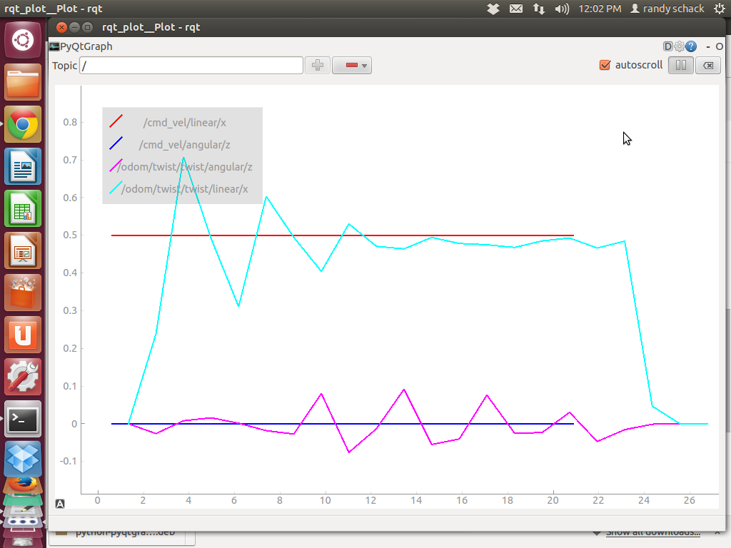
using rqt_plot to display /cmd_vel/linear/x, /cmd_vel/angular/z,
/odom/twist/twist/linear/x and /odom/twist/twist/angular/z
Example Twist commands:
$rostopic pub -r 15 /cmd_vel geometry_msgs/Twist '{linear: {x: 0.07,
0, z: 0}, angular: {x: 0, y: 0, z: 0.6}}'
$rostopic pub -r 15 /cmd_vel geometry_msgs/Twist '{linear: {x: 0, y:
0, z: 0}, angular: {x: 0, y: 0, z: 1.0}}'
(b) directly on the arduino code by adding Serial.print() statements
in the PID controller code,
to display input/output while sending "u" commands to change PID
parameters and "m" motor commands.
I prefer (b), as it allows me to directly see the raw PID Input and
Outputs, rather than the input/output speeds.
(Note: if you are taking this route, do NOT forget to disable the
additional output before using the ros_arduino_bridge; otherwise it
will not work).
Also, in case you go for (a), it is useful to be able to dynamically
set the PID parameters using dynamic_configure. I wrote some code for
that at some point in time (see [1]), but never bothered merging that
upstream.
Happy tuning!
Kristof
[1] https://github.com/KristofRobot/ros_arduino_bridge/commit/5df1f823b412b5dd355c6e9e61d93be44cf52ae3
Alex already gave excellent PID tuning instructions.
On top of monitoring the physical behaviour of your motors, I
recommend monitoring the actual PID outputs directly, through one of
the following:
(a) via ros_arduino_bridge (with Twist commands and changing the PID
parameters in the config file),
using rqt_plot to display /cmd_vel/linear/x, /cmd_vel/angular/z,
/odom/twist/twist/linear/x and /odom/twist/twist/angular/z
Example Twist commands:
$rostopic pub -r 15 /cmd_vel geometry_msgs/Twist '{linear: {x: 0.07,
y: 0, z: 0}, angular: {x: 0, y: 0, z: 0}}'
$rostopic pub -r 15 /cmd_vel geometry_msgs/Twist '{linear: {x: 0.2, y:
0, z: 0}, angular: {x: 0, y: 0, z: 0}}'
$rostopic pub -r 15 /cmd_vel geometry_msgs/Twist '{linear: {x: 0, y:
0, z: 0}, angular: {x: 0, y: 0, z: 0.6}}'
$rostopic pub -r 15 /cmd_vel geometry_msgs/Twist '{linear: {x: 0, y:
0, z: 0}, angular: {x: 0, y: 0, z: 1.0}}'
(b) directly on the arduino code by adding Serial.print() statements
in the PID controller code,
to display input/output while sending "u" commands to change PID
parameters and "m" motor commands.
I prefer (b), as it allows me to directly see the raw PID Input and
Outputs, rather than the input/output speeds.
(Note: if you are taking this route, do NOT forget to disable the
additional output before using the ros_arduino_bridge; otherwise it
will not work).
Also, in case you go for (a), it is useful to be able to dynamically
set the PID parameters using dynamic_configure. I wrote some code for
that at some point in time (see [1]), but never bothered merging that
upstream.
Happy tuning!
Kristof
[1] https://github.com/KristofRobot/ros_arduino_bridge/commit/5df1f823b412b5dd355c6e9e61d93be44cf52ae3
Randy Schack
Jan 3, 2015, 4:46:30 PM1/3/15
to ros-by-...@googlegroups.com
The motors and gearboxes are from a Powerwheels ride-on Jeep, like the ones kids have. They are 12v motors. I designed a hack for the gearbox to add quadrature encoders as described here. When having the issues I'm experiencing the logical first place to go was the untested hardware. To mitigate that possibility I've done quite a bit of testing, from manually spinning the wheels to see if I could get a consistent count to connecting them up to an oscilloscope to check for clean signals. There is an image of the oscilloscope's signal here for clarity. The image shows only the encoder's right A and B channels as my oscilloscope only has two channels but the results are similar for the left encoder. A manual test (spinning the wheels ten revolutions, counting the ticks and dividing by 10) returned the expected 1228.29 count.
Your assumptions regarding other hardware are correct - Arduino Mega, Pololu VNH5019 and Robogaia encoder shield.
I am able to get consistent results when using the Arduino serial connection to send M xx xx commands. It is only when I add ROS into the mix and attempt to send Twist commands that the problems occur. By radically changing the PID values (Kp: 3.6 Kd: 3 Ki: 0.1Ko: 50) I'm able to overcome the overshoot in ROS when running the robot up on blocks but still have issues when actually putting it in motion on the ground. It will freeze up and stop and/or change speeds randomly. Also, the settings don't completely eliminate the oscillations. Nor does the robot respond at all to settings less than 0.4m/s of linear travel or 1.8 r/s through RQT. When sending commands through the arduino serial interface I can get smooth operation as low as M 8 8.
Kristof Robot, in his response to this post, has suggested taking a closer look at the values that are being generated. I will perform those tests and report back to the forum. In the mean time I have posted the yaml file I'm using and the current Arduino code here. I've gone over that code more times that I can count looking for my mistake(s) but can't see it/them. If you have time to take a look it would be much appreciated, keeping in mind that the issue only comes up when operating from the ROS side of things so the Arduino code should be OK.
Thanks for your interest in helping to solve my dilemma,
Randy
--
Randy Schack
Jan 3, 2015, 4:57:01 PM1/3/15
to ros-by-...@googlegroups.com
Thanks for the response and suggestions. I'll start with option "A" as I'm no longer having issues with the Arduino side of things, the problems only manifest themselves when adding ROS to the mix. I've already installed the various pieces required to run rqt_plot with the idea of doing just what you suggest, you've made it much easier by providing exactly what to display! Once I get the results of the test I'll post them to the forum.
Thanks also for sharing the dynamic PID code,
Randy
Randy Schack
Jan 3, 2015, 6:00:52 PM1/3/15
to ros-by-...@googlegroups.com
Patrick,
Thanks for replying and following this issue. I see in this forum you often supply the answers us less accomplished roboticists don't seem to be able to uncover on our own. I greatly appreciate your willingness to support the open source community.
I've been fighting this issue for some time now so have done the check, recheck and then double check so many times I afraid that I'm looking right at the problem and not seeing it. It makes little sense to me that, with it working properly from the Arduino serial interface, it isn't working through ROS. The only thing I can think of is that it is a timing or publishing frequency issue.
Here are the contents of the yaml file if you have a moment to look them over:
# For a direct USB cable connection, the port name is typically
# /dev/ttyACM# where is # is a number such as 0, 1, 2, etc
# For a wireless connection like XBee, the port is typically
# /dev/ttyUSB# where # is a number such as 0, 1, 2, etc.
port: /dev/ttyACM0
baud: 57600
timeout: 0.1
rate: 50
sensorstate_rate: 10
use_base_controller: True
base_controller_rate: 10
# === Robot drivetrain parameters
wheel_diameter: 0.3028
wheel_track: 0.488
encoder_resolution: 1228 # from randys best guess. 1228.2912 from gear ratio calcs
gear_reduction: 1.0
motors_reversed: False
# === PID parameters - all modified 1/2/2015
Kp: 20 #3.8
Kd: 12 #3
Ki: 0 #0.1
Ko: 50 #50
accel_limit: 0.1 #0.1
# === Sensor definitions. Examples only - edit for your robot.
# Sensor type can be one of the follow (case sensitive!):
# * Ping
# * GP2D12
# * Analog
# * Digital
# * PololuMotorCurrent
# * PhidgetsVoltage
# * PhidgetsCurrent (20 Amp, DC)
sensors: {
#motor_current_left: {pin: 0, type: PololuMotorCurrent, rate: 5}, #uncommented out 09/18/2014
#motor_current_right: {pin: 1, type: PololuMotorCurrent, rate: 5}, #uncommented out 09/18/2014
#ir_front_center: {pin: 2, type: GP2D12, rate: 10},
#sonar_front_center: {pin: 5, type: Ping, rate: 10},
Proportional: {pin: 5, type: Ping, rate: 10},
arduino_led: {pin: 13, type: Digital, rate: 5, direction: output}
}
The commented out values in the pid section are the values I got the best results with but they still didn't work when actually running the robot on the ground vs running it up on blocks. As I mentioned in the response to P Tiago Pereira using those parameters led to unresponsiveness at smaller values (less than 0.4m/s and less than 1.8r/s).
I'm going out to the shop to perform the tests Kristof Robot suggested in his response and will post the results to the forum.
Thanks again for all you do,
Randy
Patrick Goebel
Jan 3, 2015, 9:34:21 PM1/3/15
to ros-by-...@googlegroups.com
Hi Randy,
Just to confirm something: You say below that using the Arduino serial connection you are getting smooth operation as low as "m 8 8". Is your robot on blocks when you do that test or on the ground? I'm still drawing a blank on your problem but I want to make sure the "m 8 8" is working with your robot on the ground, otherwise it could be a motor torque issue (I'm grasping a straws...).
--patrick
Randy Schack
Jan 3, 2015, 11:53:35 PM1/3/15
to ros-by-...@googlegroups.com
I haven't put it on the ground while running it through the Arduino but I have put a strong load on the motors by grasping the wheels with my hands. In those instances the motors kept their speed until I could no longer hold on and once I let go, depending on whether I let loose immediately (where they would over speed for a moment and then return to the set speed) or if I slowly reduced the pressure (where it would maintain a "close to constant" speed).
I've been doing the tests in rqt_plot that Kristof Robot suggested and will post them tomorrow when I can format them in a manner that makes sense visually. After having run a few different test plots this evening I'm hopeful the full set of plots will uncover some new information.
Thanks Again,
Randy
Randy Schack
Jan 4, 2015, 12:43:41 PM1/4/15
to ros-by-...@googlegroups.com
As discussed here is an svg that contains screen shots of rqt_plots of all of the settings suggested plus a few that started to give other results. It's rather large (6mb) so may be slow to load.
I haven't tried to analyse the data yet but thought I'd post it sooner rather than later in case there was interest from the forum (plus if anyone has suggestions I'd love to hear them!). If I get better results from further tests I'll add them to the svg.
Randy
On Fri, Jan 2, 2015 at 11:15 PM, Kristof Robot <kri...@gmail.com> wrote:
Kristof Robot
Jan 4, 2015, 2:47:38 PM1/4/15
to ros-by-...@googlegroups.com
Randy,
A wild guess, but I wonder whether there is a problem with the link
between your ROS pc and the Arduino. Perhaps there is interference on
this link and/or gets overloaded - missing/garbling messages. I am
assuming you hooked up the Arduino Mega via USB directly to the ROS PC
on the robot?
Also, since you built your own encoders (they look very impressive, by
the way!), this is a potential weak point (as you already mentioned).
You could try verifying the encoder values that ROS sees, by logging
the results of following line in base_controller.py:
left_enc, right_enc = self.arduino.get_encoder_counts()
E.g. just add a printout:
rospy.loginfo(str(left_enc) + " " + str(right_enc))
Additionally, I see that you kept the default values in your yaml file
- which should work - but perhaps you could try with a very low value
for "base_controller_rate" (1 or lower). At the same time I would
disable all sensors for a moment (what does the "Proportional" sensor
do?).
If that works better, that also points to problems on your communication line.
Cheers,
Kristof
Randy Schack
Jan 4, 2015, 3:09:52 PM1/4/15
to ros-by-...@googlegroups.com
Thanks for the suggestions, I'll try them all!
After creating the chart of plots I quit trying to figure out why Patrick's pid values wouldn't work through ROS and started tuning per your directions. I'm far from being done but so far settings of: Kp: 5.2 Kd: 0 Ki: 0 Ko: 50 are giving the result indicated in the attached screen shot. Smaller P values never get above about 3.6 m/s when shooting for 5 m/s and larger numbers overshoot to maximum motor speeds.
Randy
Kristof Robot
Jan 4, 2015, 3:11:10 PM1/4/15
to ros-by-...@googlegroups.com
Randy,
Your last PID parameters (Kp=3, ...) definitely seem to work best. But
it seems that they make your robot only move at speeds > 0.3 or so
(0.2 does not seem to work, 0.5 seems to work fine).
I noticed that your wheels seem to be huge (30 cm diameter). What I
suspect is that your motors are simply not capable of driving them at
the low speeds that you command them (<=0.2).
Since you have reasonable results with a speed of 0.5m/s (which is
very fast for an indoor robot), I would tune your PID for speeds
around that figure (and work with speeds around that figure).
Alternatively, if you need your robot to move slower, you should go
for either other motors, or smaller wheels.
Cheers,
Kristof
Kristof Robot
Jan 4, 2015, 3:21:45 PM1/4/15
to ros-by-...@googlegroups.com
To figure out what speeds your motor/wheel combo is capable of, you
could send it PWM commands directly. You will notice that at low
values it will not move at all (the "dead-band"), and from a certain
value onwards it should start running reliably - that is your minimum
speed.
At some point in time I added support for sending PWM commands using
ros_arduino_bridge, and also for setting the "MIN_PWM" to jump across
the initial "dead-band" - see
https://github.com/KristofRobot/ros_arduino_bridge/commit/2e2762c1ce7da0946d21debe007f6eea2bfa50a1
I never got around pushing this upstream however.
If this turns out to be of any help to you, I'll consider pushing this upstream.
Cheers,
Kristof
Randy Schack
Jan 4, 2015, 3:36:19 PM1/4/15
to ros-by-...@googlegroups.com
I think you are correct, with the 5.2 value I can get the motors to run at 0.3 m/s and at 0.2 m/s the motor will try and then stall. I'll see what I can find in the way of geared or more sensitive motors.
I tried changing out the usb cable and eliminating the sensors to no avail. I believe the proportional sensor is related to a sonar ping of a sensor if that type sensor is used.
Thanks for all your help.
Randy
Randy Schack
Jan 4, 2015, 3:51:52 PM1/4/15
to ros-by-...@googlegroups.com
Thanks! I'll try it right now.
BTW, thanks for the kudos regarding the quadrature encoders. They were a way to use the powerwheels gearboxes I saved from my sons Jeep while giving me an excuse to use the 3D printer (before designing the robot!).
Randy
Randy Schack
Jan 4, 2015, 6:50:03 PM1/4/15
to ros-by-...@googlegroups.com
Kristof,
The PID additions are very helpful, I've been tuning all afternoon (California time) and now have a new issue, when putting more load on the wheels (by rubbing my had against them) the speed doesn't recover like it used to. Any suggestions?
Thanks in advance,
Randy
Kristof Robot
Jan 5, 2015, 2:09:34 AM1/5/15
to ros-by-...@googlegroups.com
Hi Randy,
Seems that your proportional term is too low in that case - you could
try increasing Kp (slowly).
But it would probably better to completely restart your PID tuning
from scratch using the instructions of Alex, and with the new
knowledge that you want to tune at a speed of around 0.4 (i.e. put Kd
and Ki to 0).
But before doing that I would manually check the behaviour of your
motors at different PWM values. If that behaviour is not reasonably
linear, your PID controller has little chance.
Kristof
Randy Schack
Jan 5, 2015, 11:39:35 AM1/5/15
to ros-by-...@googlegroups.com
Thanks for the advice. Your help has led me to think the robot will not perform well at low speeds as configured.
I've ordered a couple of slower speed motors (7750 rpm vs 19,000+) as well as some gears, bearings and shafts to make a gear reduction adapter for use with the existing motors. I'll try both options separately and report back.
The gear reduction sounds promising as a quadrature encoder could be integrated eliminating the modifications to the gearbox on future implementations.
Thanks again for your input,
Randy
Reply all
Reply to author
Forward
0 new messages