SDRAM works

Casainho
imx-bootlets and use this init function: init_ddr_mt46v32m16_96Mhz
I ended by using the original code and see if something works. Here the main():
poweron_pll(); <----- Inits PLL to 480Mhz. Although clock here
still be the 24MHz from cristal.
delay_us(11000);
/* Enable the VDDMEM to 2.5V */
turnon_mem_rail(2500); <----- Enables de VDDMEM rail to 2.5V, I
verified doing step by step debug and oscilloscope.
delay_us(11000);
/* enable pins as for working with EMI,
* for external RAM
*/
init_emi_pin(0, PIN_DRIVE_12mA); <----- Enables the pins for EMI
(external memory interface). Pins must be mux'ed to EMI pheripherial,
etc.
disable_emi_padkeepers(); <----- don't know what this code does.
/* init the EMI clock at 96MHz */
init_clock(); <----- The clock of 480MHz from PLL is here divided
to 96MHz, for SDRAM. If we want higher or lower speed for SDRAM, we
can change this function.
delay_us(10000);
init_ddr_W9425G6EH_5_96Mhz(CE); <----- This is a copy of the code
of init_ddr_mt46v32m16_96Mhz()
value = HW_DRAM_CTL08_RD();
value |= BM_DRAM_CTL08_START;
HW_DRAM_CTL08_WR(value); <----- Starts the clock/SDRAM???
exit_selfrefresh(); ???
set_port_priority(); ???
entry_auto_clock_gate(); <----- a way to have low power, I think
MCU clock slows while waiting for SDRAM data
change_cpu_freq(); <----- CPU freq goes from the 24MHz cristal to
the 454MHz from PLL :-) Verified with osciloscope.
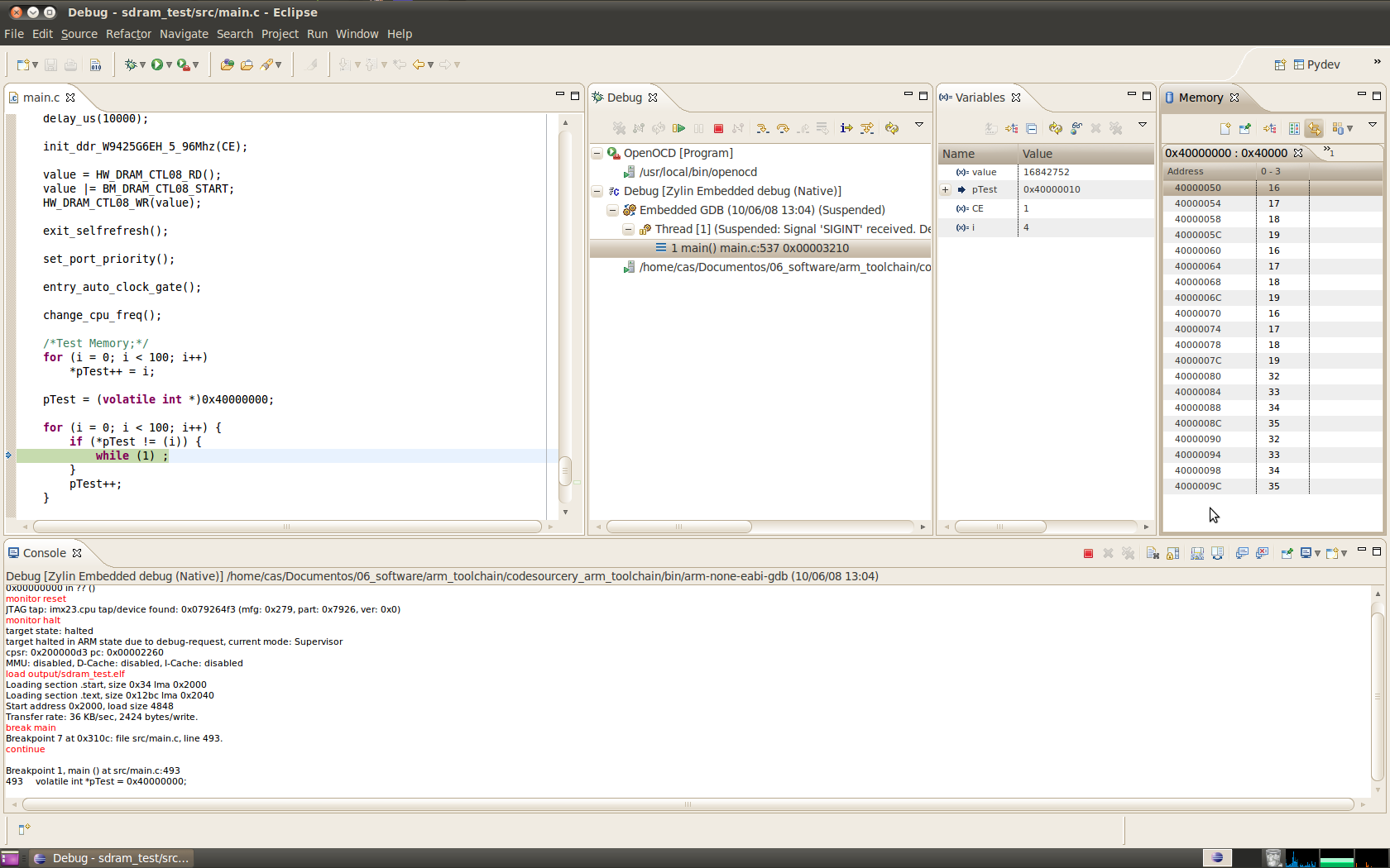
/*Test Memory;*/
for (i = 0; i < 100; i++)
*pTest++ = i;
pTest = (volatile int *)0x40000000;
for (i = 0; i < 100; i++) {
if (*pTest != (i)) {
while (1) ;
}
pTest++;
}
So, on the 0x40000000 (begin of SDRAM), we should have the values:
0, 1, 2, 3, 4, 5, 6, 7, 8, 9, 10, 11, 12, 13, 14, 15... 99
But I got:
0, 1, 2, 3, 4, 0, 1, 2, 3, 4, 0, 1, 2, 3, 4, 0, 1, 2, 3, 4, 12, 13,
14, 15, 12, 13, 14, 15, 12, 13, 14, 15, 12, 13, 14, 15, etc..
For sure something is wrong on the SDRAM init :-) -- the mt46v32m16
isn't the same as ours, it even have a different size :-)
Does anyone knows what values of registers do I need to change?
The code is on Lyre SourceForge SVN:
http://lyre.svn.sourceforge.net/viewvc/lyre/propendous-imx233_board/firmware/sdram_test/
--
Cumprimentos,
Jorge Pinto

john cooper
> So, on the 0x40000000 (begin of SDRAM), we should have the values:
> 0, 1, 2, 3, 4, 5, 6, 7, 8, 9, 10, 11, 12, 13, 14, 15... 99
>
> But I got:
> 0, 1, 2, 3, 4, 0, 1, 2, 3, 4, 0, 1, 2, 3, 4, 0, 1, 2, 3, 4, 12, 13,
> 14, 15, 12, 13, 14, 15, 12, 13, 14, 15, 12, 13, 14, 15, etc..
Is that data sequence correct? Repeat data modulus 5 for 0..4
and modulus 4 for 12..15 ? Data aliasing modulus 2^n typically
indicates a stuck address line or incorrect controller multiplexing
config relative to either RAS/CAS bit width in the physical device.
Eg: if you're finding data aliasing after 4x 32-bit ints on a
16-bit DDR device, A3 seems like it is somehow stuck.
But given your test program above I'd expect to see latter data
overwriting prior data if a decode alias bug existed so I'm unsure
what the issue may be.
-john
Casainho
From: Opendous Support <opendous...@gmail.com>
Date: Tue, Jun 8, 2010 at 5:14 PM
Subject: Re: SDRAM works
To: Casainho <casa...@gmail.com>
Casainho,
I have been going through the datasheets and code to figure out
SDRAM initialization and will be looking into this.
I want to greatly thank you for putting all the power and SDRAM code
together as it saved me all that work.
I have slightly modified your code by adding Debug UART. Please
look over the code and see if I am doing something wrong.
I use a 16MHz USB AVR (8MHz has too high an error rate at
115200baud) loaded with LUFA's latest USBtoSerial firmware and launch
it with:
gtkterm --port /dev/ttyACM0 --speed 115200
Later,
Matt,
Opendous Inc.
--
Cumprimentos,
Jorge Pinto

Bob
data bits are always zero, bits 4-5 ?
Bob
works as well as it does!
john cooper
> I think that was a typo, must be 0,1,2,3,0,1,2,3... I am thinking some
> data bits are always zero, bits 4-5 ?
Or just stuck at either level. Could be open too over that short
of a test sequence. My guess is A3 given it is a 16 bit device.
Incidentally given a small alias it is likely an interconnect issue
vs. controller setup issue. The latter would arise as aliasing after
the number of CAS bits rolls over which is something to keep in mind
going forward.
-john
Bob
One handy thing with a JTAG debugger is to display a memory dump and
keep pressing refresh. Any dodgy timing on the reads will show bits
changing randomly.
On 8 June, 17:41, Casainho <casai...@gmail.com> wrote:
> ---------- Forwarded message ----------
> From: Opendous Support <opendous.supp...@gmail.com>
> Date: Tue, Jun 8, 2010 at 5:14 PM
> Subject: Re: SDRAM works
> To: Casainho <casai...@gmail.com>
>
> Casainho,
>
> I have been going through the datasheets and code to figure out
> SDRAM initialization and will be looking into this.
>
> I want to greatly thank you for putting all the power and SDRAM code
> together as it saved me all that work.
>
> I have slightly modified your code by adding Debug UART. Please
> look over the code and see if I am doing something wrong.
>
> I use a 16MHz USB AVR (8MHz has too high an error rate at
> 115200baud) loaded with LUFA's latest USBtoSerial firmware and launch
> it with:
> gtkterm --port /dev/ttyACM0 --speed 115200
>
> Later,
> Matt,
> Opendous Inc.
>
> > --
> > Cumprimentos,
> > Jorge Pinto
>
> --
> Cumprimentos,
> Jorge Pinto
>
>
>
> 92KViewDownload
>
> opendous_sdram_testing-2010-06-08-1200.zip
> 665KViewDownload
john cooper
> I am also thinking the timing will be off, I am surprised that it
> works as well as it does!
DRAM is pretty interesting stuff. In the past I'd designed
discrete dram controllers where the prototype had stopped
refresh when the system went into reset for seconds. Even in
that case the data content was mostly intact even after such a
long decay. More anecdotal than useful I'll admit but IME even
gross timing and refresh violations can go unnoticed without
exhaustive testing.
-john
Casainho
<opendous...@gmail.com> wrote:
> Later on I will need to write random data to SDRAM so I will have to
> communicate via UART as JTAG would be too slow.
>
> You can use any USB to Serial device to connect to the Debug UART. If
> you have a FT2232-based device it will work just as well. UART is
> DBUS0,1 pins so you can even use your JTAG connector.
Ok :-)
> What results do you get using my code?
Well, took me a few time to be able to debug it, because it was giving
errors always. The lines in the midle of the code:
/* Enable parallel JTAG, 12mA drive and the MUX pins for it */
HW_PINCTRL_MUXSEL4_CLR(0x3FFF);
HW_PINCTRL_MUXSEL4_SET(0x2AAA);
HW_PINCTRL_DRIVE4_CLR(0x3FFF);
HW_PINCTRL_DRIVE4_SET(0x2AAA);
HW_DIGCTL_CTRL_CLR((1 << 1) | (1 << 3) | (1 << 6));
They simple should disable temporary parallel JTAG.
Well, I get the same results with your code. I think.
I am seing that doing debug, I can write directly a value to a piece
of memory. If I write 0xFFFFFFFF, the value stay instead 0xFFF3FFF3
--> 1111111111110011 , so I will be looking with oscilloscope to that
pins.
I agree with John's comment
Matt, why don't you send your messages to Rockboxplayer group, so we
all receive your messages?
> about the stuck pin but I seem to be getting an error on correct
> behavior which implies I am overlooking something very simple. The
> equality check fails but then the data is read back correctly.
Bob: I suspect without optimisation turned on, each reference to
*pTest will reread SDRAM, so that is why he gets apparent false errors
it would be better to do
val = *pTest;
if (val != i) printf "got %x expected %x\n", val, i);
The fact that he gets these errors suggest the write was successful
but the reads are intermittent
Bob: I see Matt declared his vars as volatile, so that explains the funny output
----
So, maybe SDRAM is ok, and I have 2 pins shorted. I have with me the
BoB board, I will assembly the SDRAM part of the board and test it :-)
Casainho
> one. After the board for the buttons and finally audio and enclosure
> :-)
Matt, do you have one LCD for you? do you have any LCD to sell??
I am interested on the 2.4'' LCD plus components. If you will buy some
material from Digikey, you could also buy the LCD and components for
me. And maybe Bob will want also.
Casainho
---------- Forwarded message ----------
From: Casainho <casa...@gmail.com>
Date: Tue, Jun 8, 2010 at 11:23 PM
Subject: Re: SDRAM works
To: Opendous Support <opendous...@gmail.com>
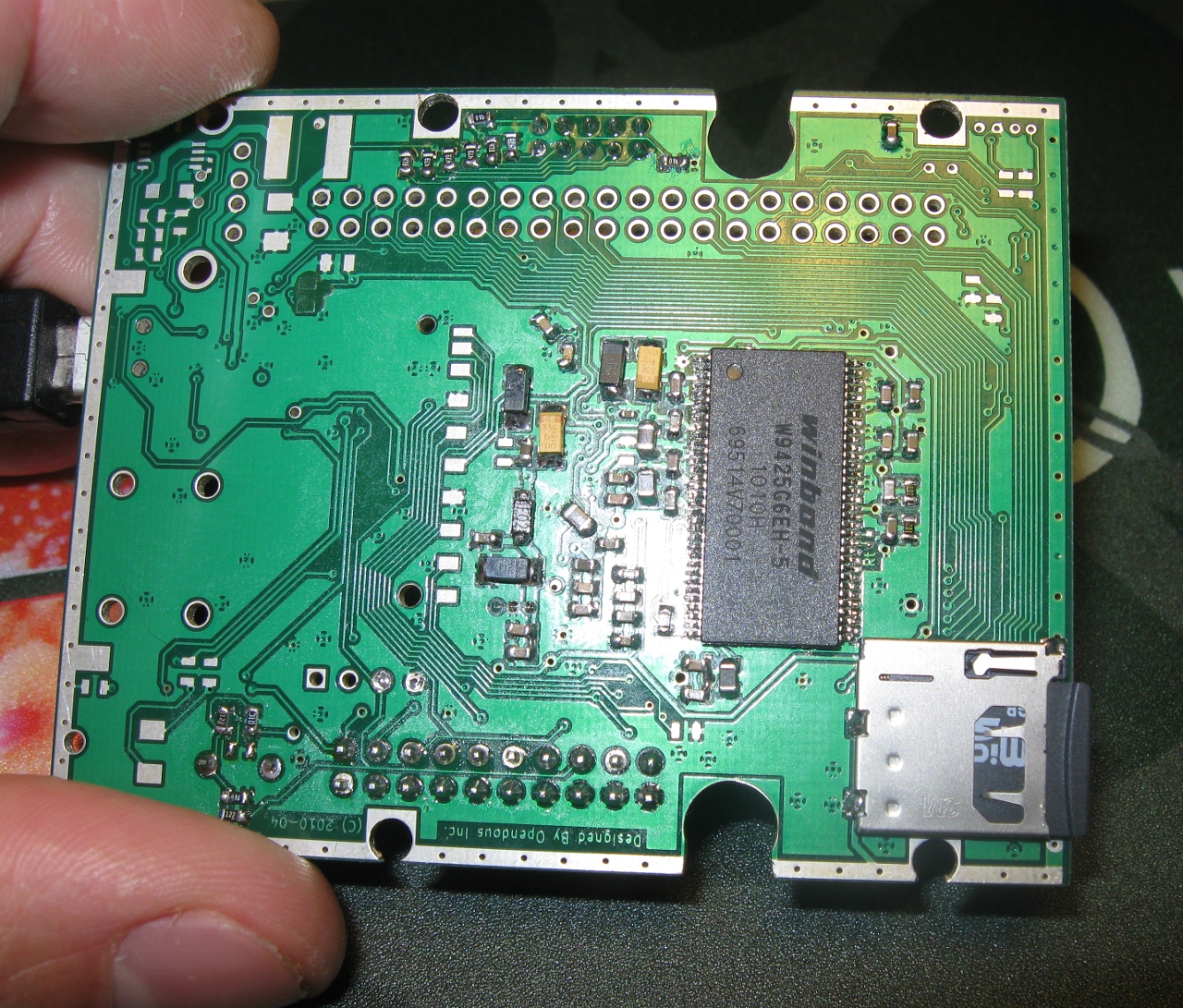
Ok, finally my SDRAM works :-) -- and I am sure the SDRAM on Matt
board is also working.
What was the problem? apparently bad solder on imx233 pins, some pins
that goes to SDRAM.
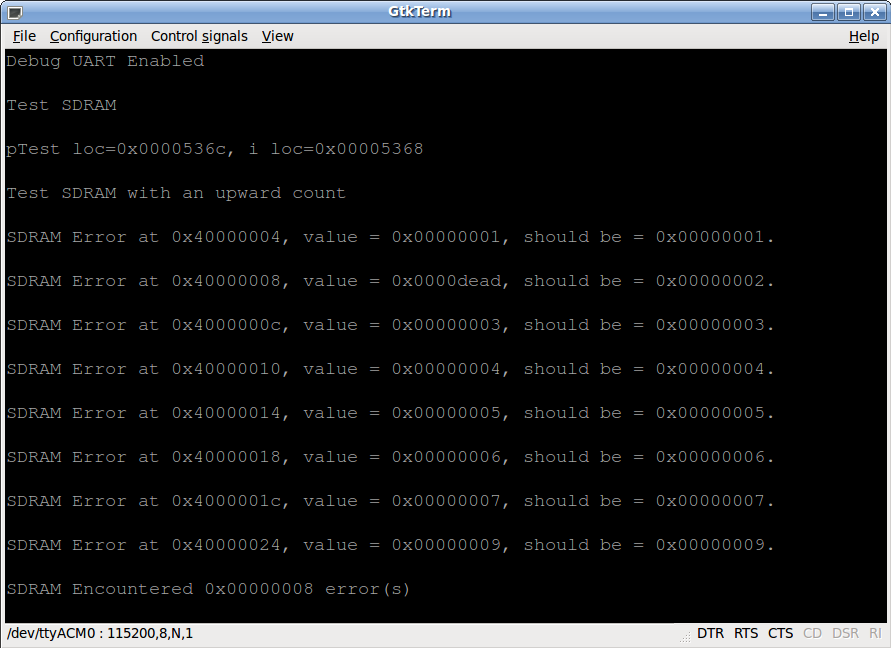
I used a code to fill the full 32Mbytes with 1 and tested them. After
filled with 0 and tested again. I used volatile variables to hold the
values, so the values and for sure written and readed from SDRAM. I
commited the code to SVN.
First I did init the SDRAM at 96MHz and then at 133MHz, it works on
both situations. My oscilloscope just measures up to 50MHz but I were
able to see a small signal of 133MHz and 96Mhz.
Tomorrow will finish to assembly Bob SDRAM on his board and test it,
before sending him.
The imx233 gets a bit hot, because I am powering it by USB and it runs
from internal linear regulators. Actual code do not change to DC-DC,
but powering the board from battery will run from DC-DC, something I
can test later. Or use the code from FreeScale to enable the DC-DC.
Whats follow next? -- I would prefer to have next the LCD, the 2.4''
one. After the board for the buttons and finally audio and enclosure
:-)
Matt, you did a great job with this board ;-)
--
Cumprimentos,
Jorge Pinto
Casainho
<opendous...@gmail.com> wrote:
> Later on I will need to write random data to SDRAM so I will have to
> communicate via UART as JTAG would be too slow.
Maybe it's a bad idea random data. Bob sent me a link with good
information for testing memories:
http://www.embedded.com/2000/0007/0007feat1.htm
And I am doing now as author says, write 1 and verify, after write
zeros and verify. It takes many seconds for our the 32MBytes SDRAM.
I finished to solder Bob board and it just passed on the test :-)
----
As for LCD and buttons, I am looking for getting something as the
gameboy, buttons that would let people "play" on a tracker, just like
this: http://www.youtube.com/watch?v=RotoNE_zMqo
This an a big advantage that Lyre haves! it will be able to synthesize
music! and not just play recorded one. And for this, I think Lyre
needs a relative good LCD like the 2.4'' (but I think a 1.8'' would
also be good because is small, for a small portable device).
For LCD, I do not have a big problem, I am sure the printed enclosure
will make a good frame for it. And for buttons, maybe we could use
cheap ones like the one used now for PWSITCH. Maybe we could also
print that kind of cross for directional buttons... and there are
people printing with white, black, red, green and blue plastic :-)
The PCB do not need screws! the enclosure can be made in a way to
press the PCB against it. Next board do not need to have holes for
screws.
Even the battery, we can avoid to buy the support and instead design
and print the enclosure for hold the batteries. There are detached
springs on selling, for use in this cases, to make contact with
battery and to help hold it.
Actual board is a bit large, so, the 2.5'' LCD will be ok. But later I
would prefer to make the nano concept, with a real nano board and LCD.
Even I think we could use just the uSDCard for firmware + audio files,
because users will not change a lot the uSDCard since they will need
to connect the Lyre to PC for charge and then they can transfer the
files by USB.
Well, this are ideas, let's see what we will do in future :-)
Here a video of Lyre bird, a strange bird as Bob said :-)
Casainho
<opendous...@gmail.com> wrote:
> Casainho,
>
> So SDRAM works well for you? It still does not work for me. Please
> test the included code distributions. I use arm-linux- instead of
> arm-none-eabi- so make sure to change this at the top of the makefile.
> The second distribution uses eclipse native compiling.
YES, it works! It worked on my board and Bob board!
I tested one of your codes (that is the same I used + you serial
prints) and it works perfectly, but I had to comment the serial calls,
because I do not have serial.
Very nice, you didn't changed nothing on Eclipse debug and openocd
files, so they were with the paths to my computer files, I just
connected the JTAG to board, builded the code and run/debuged it 3
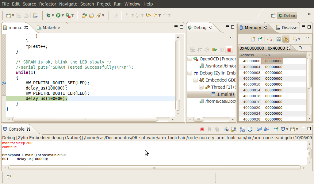
times, always with the same result -- SDRAM is ok. I am sending a
screenshot, where you can see all 00000000 to some addresses of SDRAM,
since code end by write 0000 and read, testing them.
I am also sending back the code. The code on SVN MUST work, since is
the same and I tested it a few times.
Casainho
<opendous...@gmail.com> wrote:
> Casainho,
>
> Please create a reference image for the microSD card you are using:
> dd if=/dev/sd? of=casainho_JTAG_bootstream.img count=80
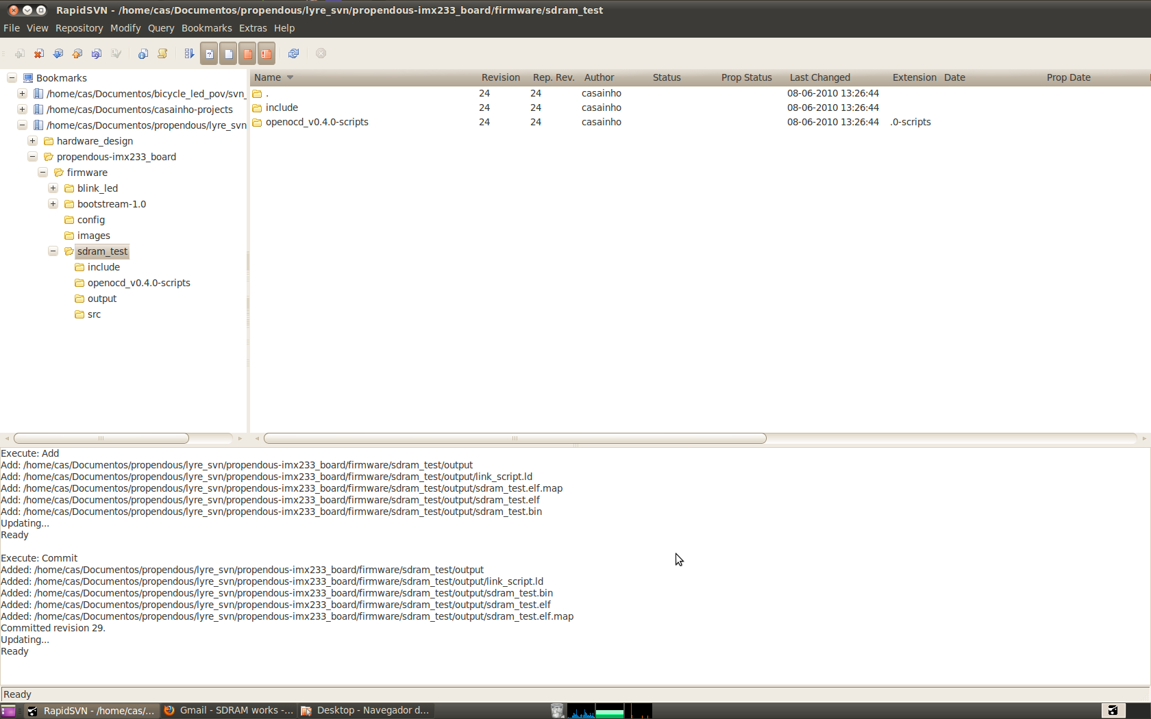
I just did commit to the elf file, bin file and the one ready to place
on uSDcard. Follow the README file :-)
> Also, are you using HW_PINCTRL_DRIVE4 for JTAG pin control? It is
> HW_PINCTRL_DRIVE8 that contains the SSP1/JTAG pins:
> HW_PINCTRL_DRIVE8_CLR(0xFFFFFFFF);
> HW_PINCTRL_DRIVE8_SET(0x22222202);
No, I think you are mistaken. Verify again the datasheet. I am sending
a screenshot of it.
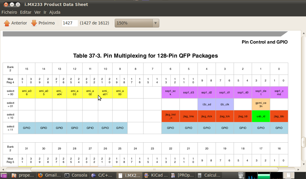
Casainho
<opendous...@gmail.com> wrote:
> Casainho,
>
> Thanks, it might be that serial is interfering with the SDRAM test.
Maybe.
> Please try the original firmware as well with serial output. You
> can use your JTAG adapter (which I assume is based on the FT2232D).
> TDI = RXD = ADBUS1 and GND are the only connections you need. You may
> need to reprogram your FT2232's EEPROM. Or, change the baud rate in
> serial.h to a slower speed by adjusting CONFIG_BAUDRATE and then use a
> USB AVR loaded with LUFA's USBtoSerial firmware. Start GTKterm with
> gtkterm --port /dev/ttyACM0 --speed 38600 or similar.
I don't need serial, at least for now.
> Which version of OpenOCD are you using? I am using the 0.4.0 release.
Me too! as you can see for the folder name where the scripts are for the imx233.
Casainho
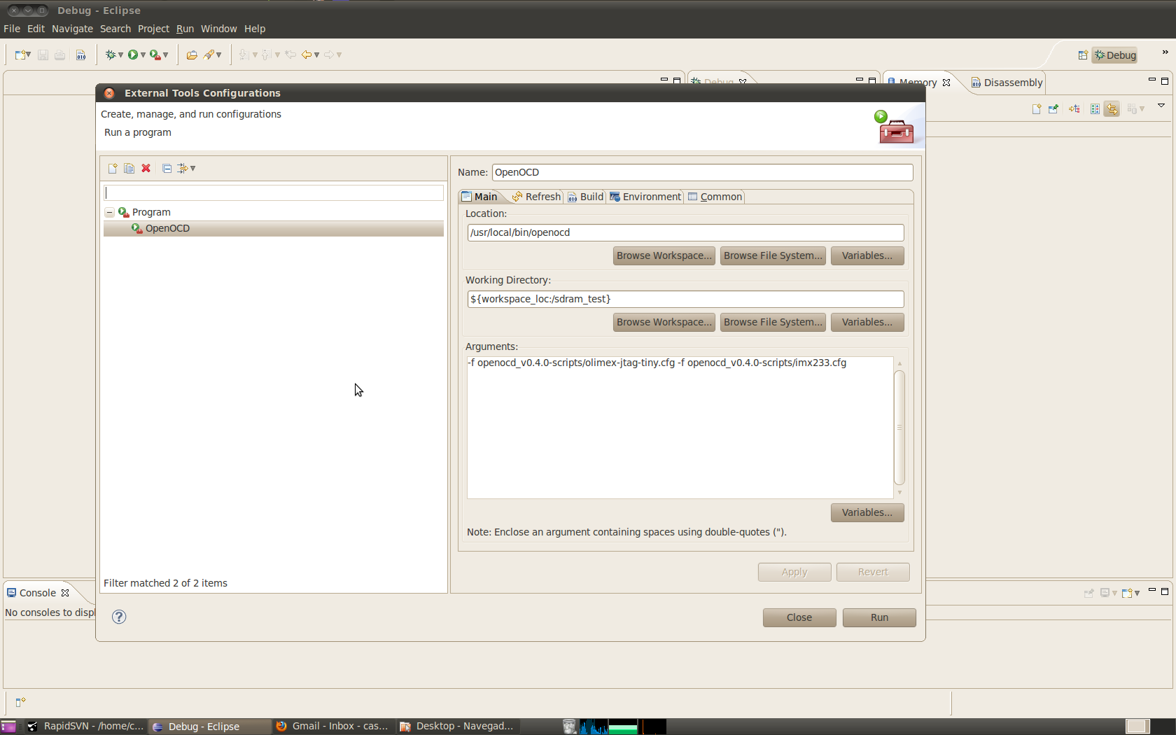
From: Casainho <casa...@gmail.com>
Date: Wed, Jun 9, 2010 at 4:36 PM
Subject: Re: SDRAM works
To: Opendous Support <opendous...@gmail.com>
> still have problems with it.
First, I boot the imx233 with uSDCard, with that image that blinks the
LED and enable parallel JTAG.
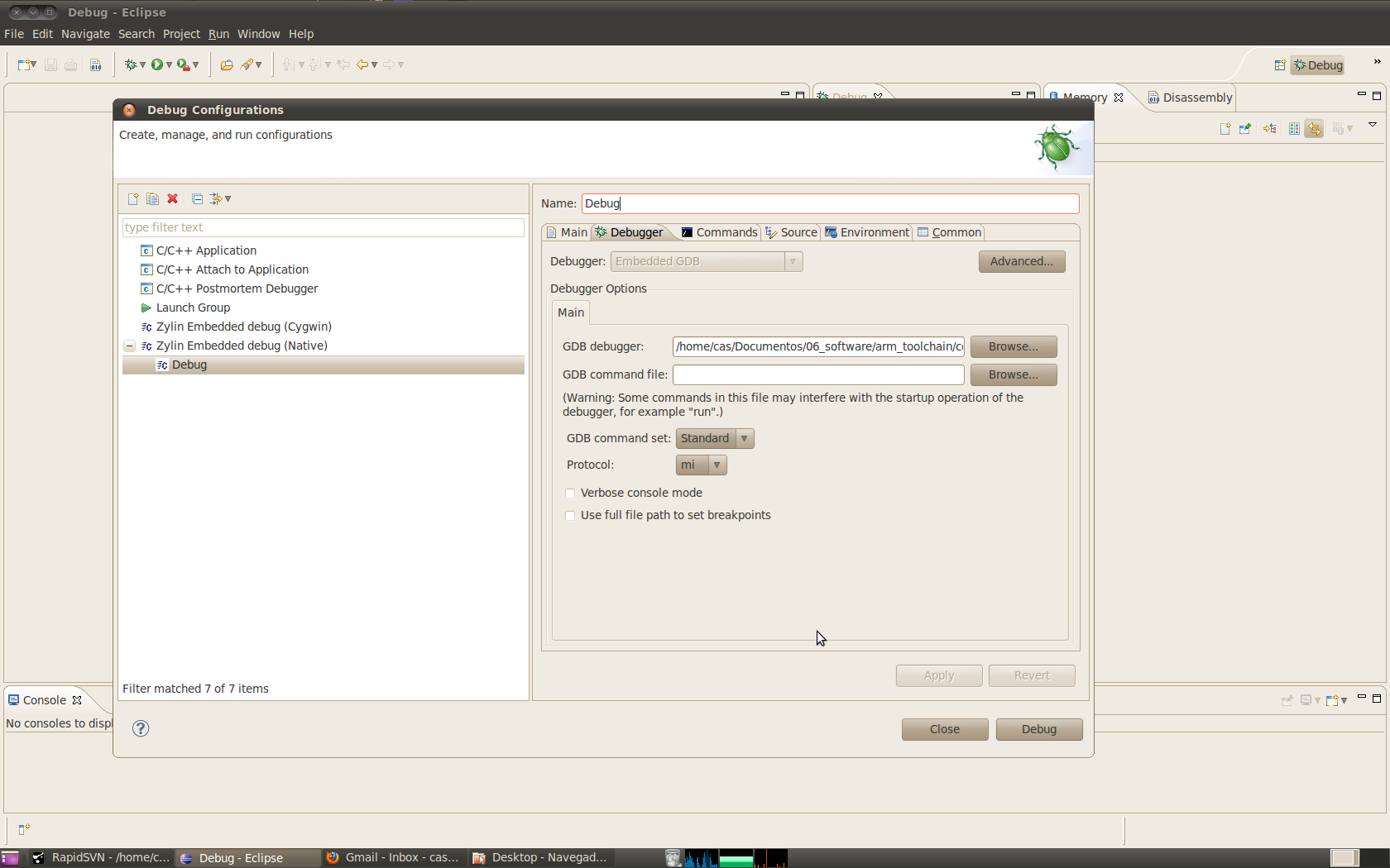
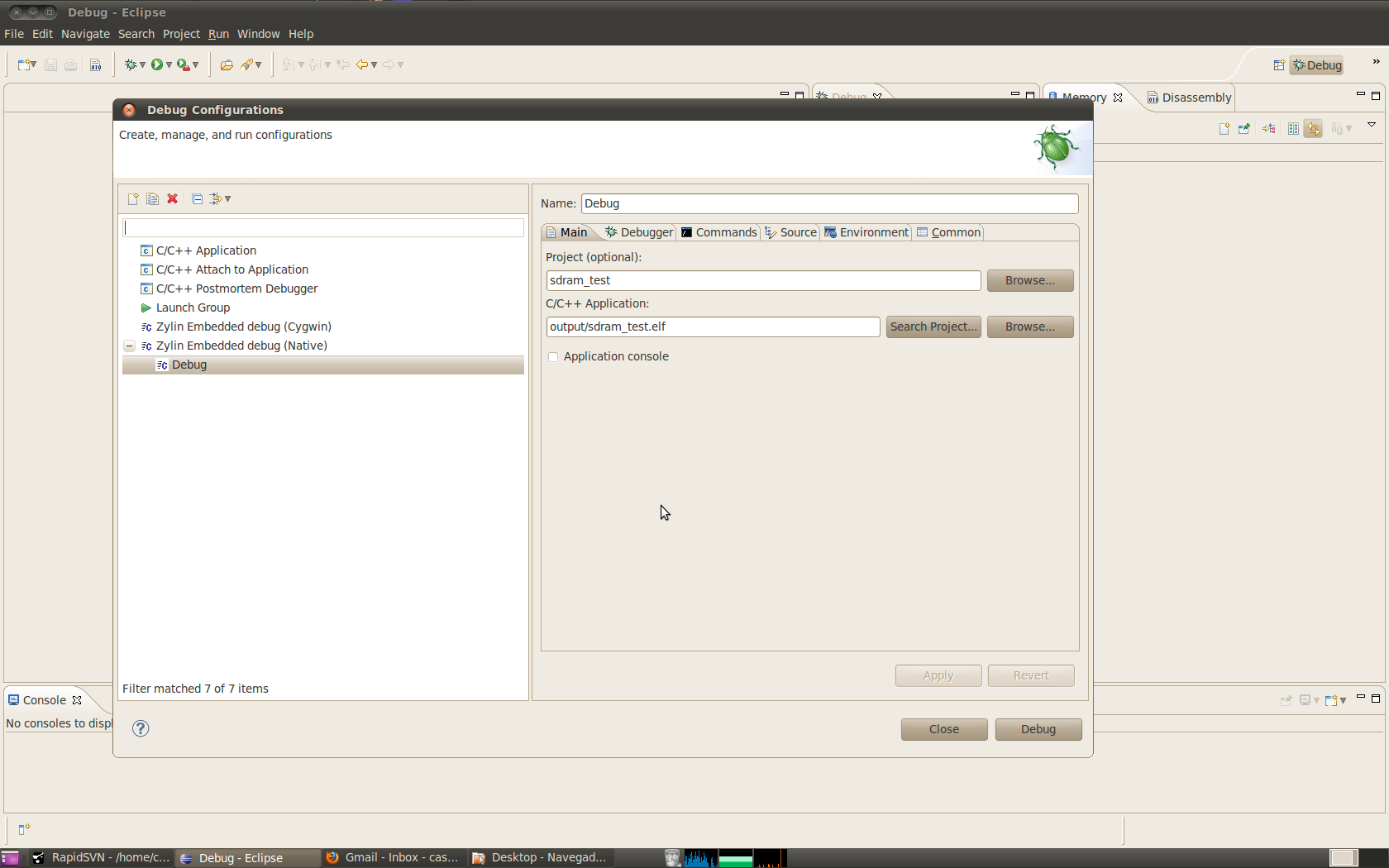
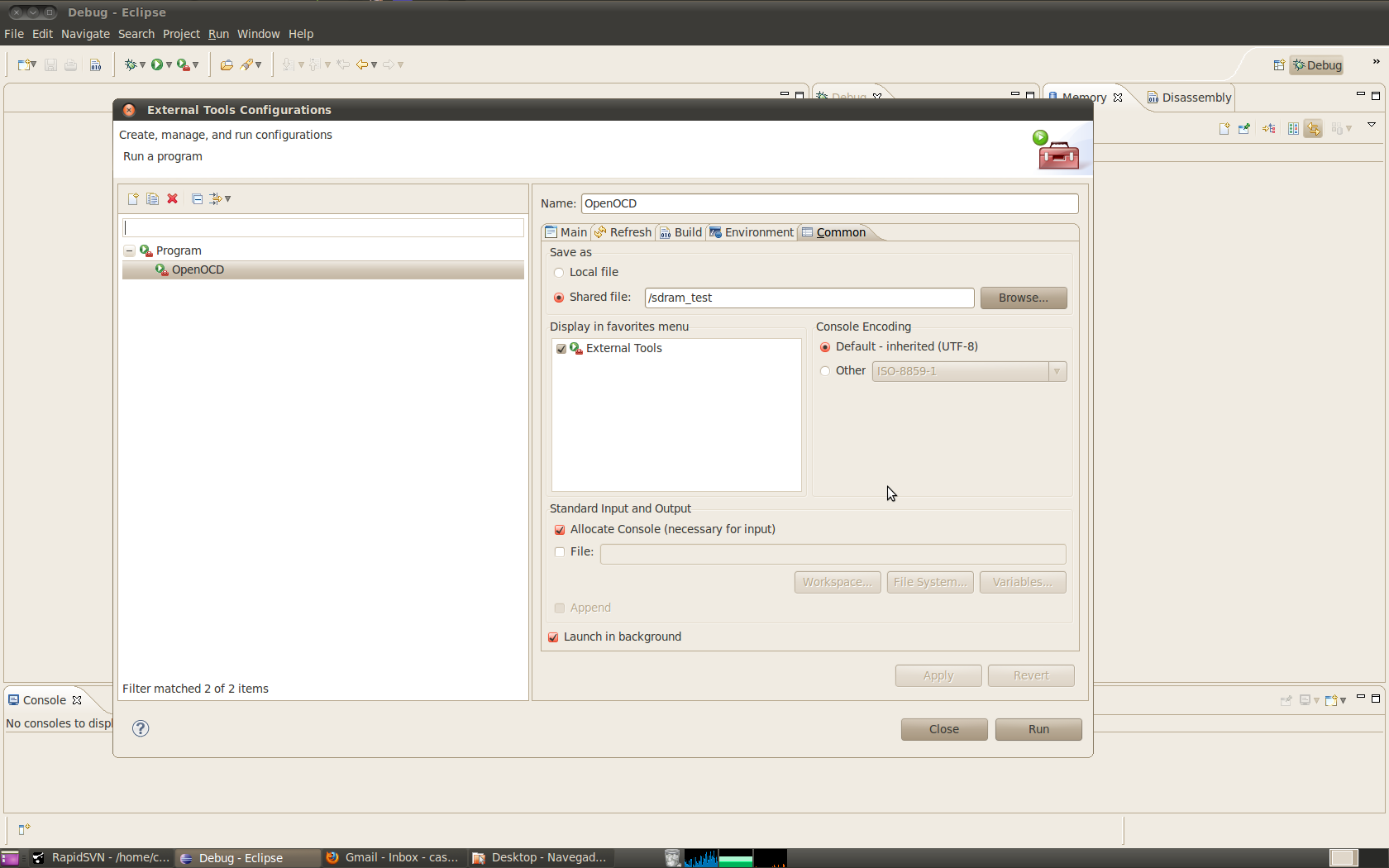
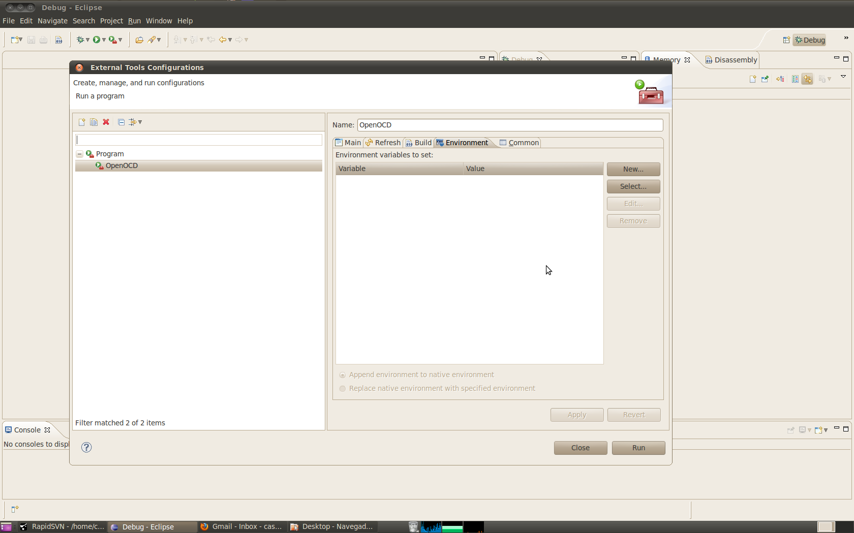
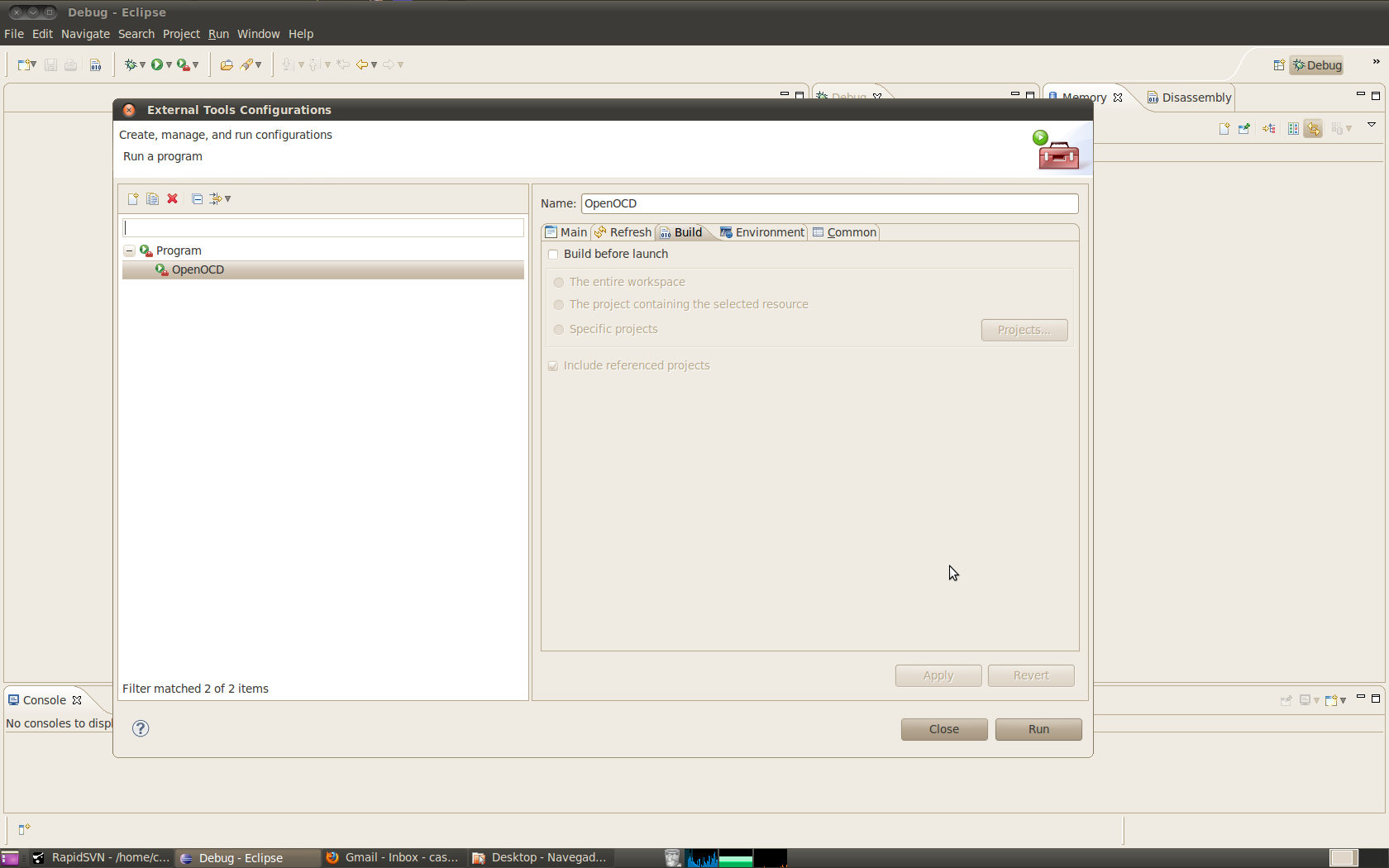
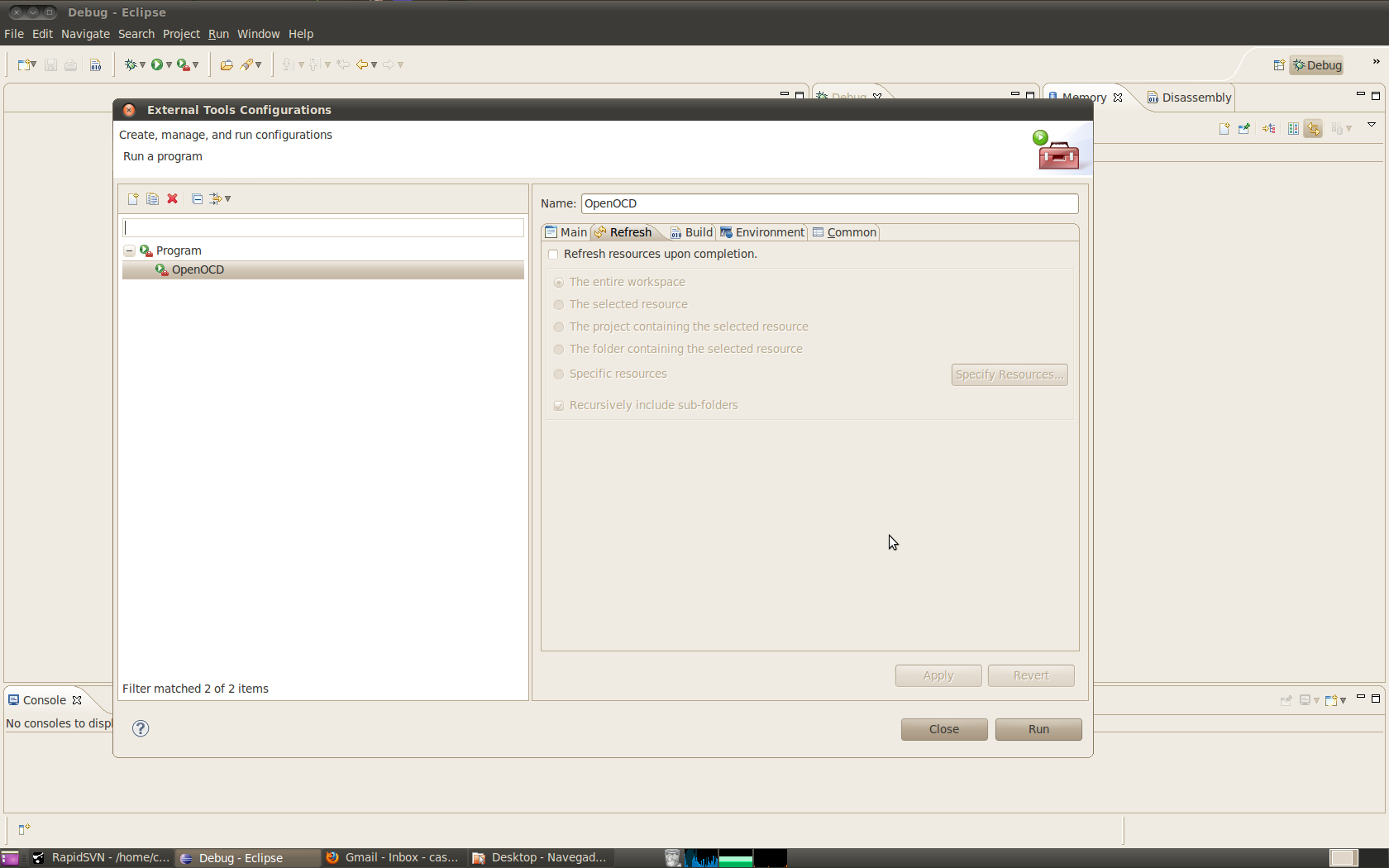
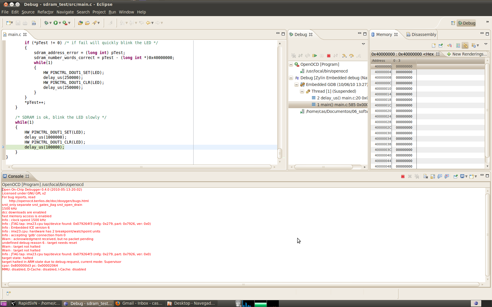
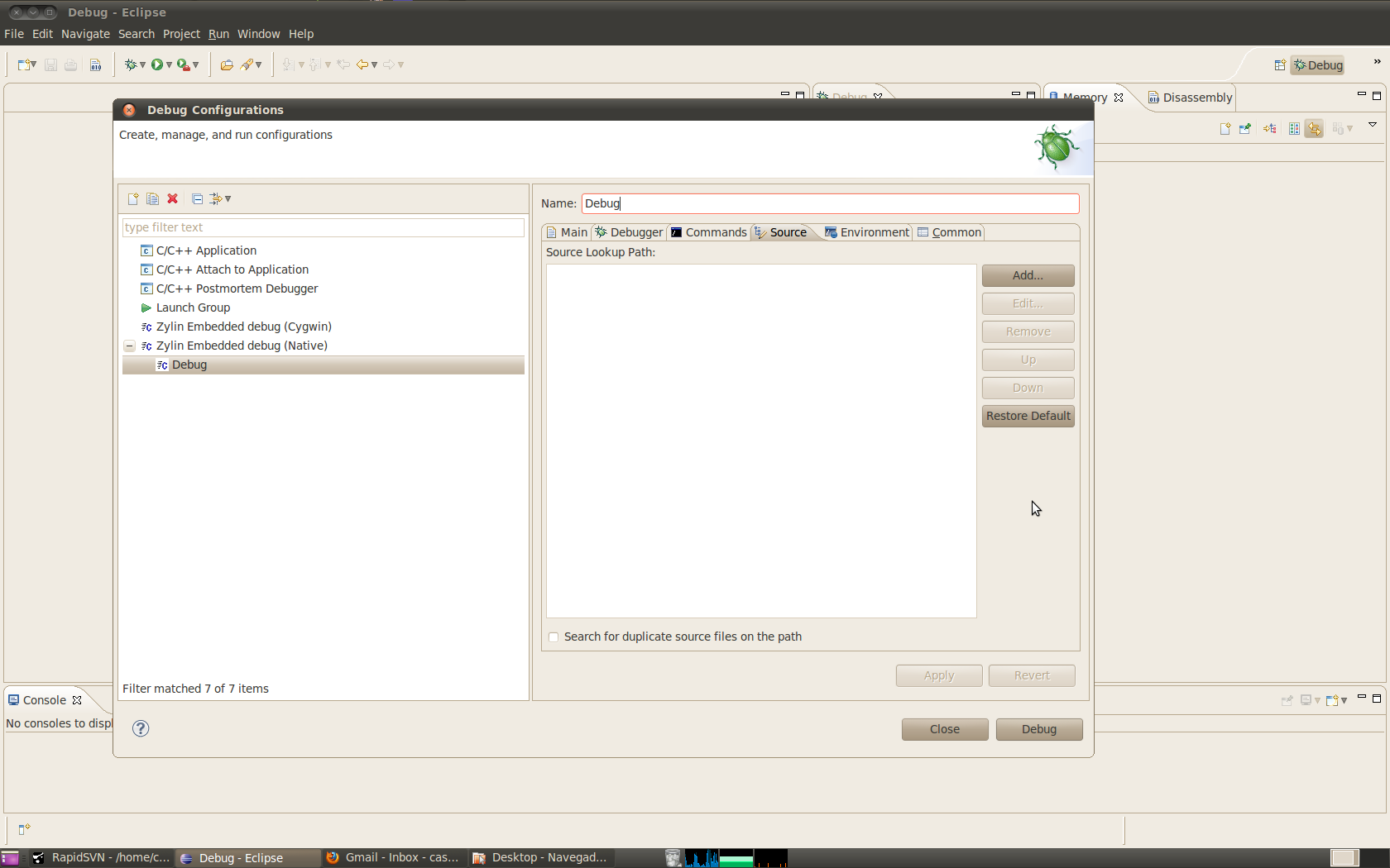
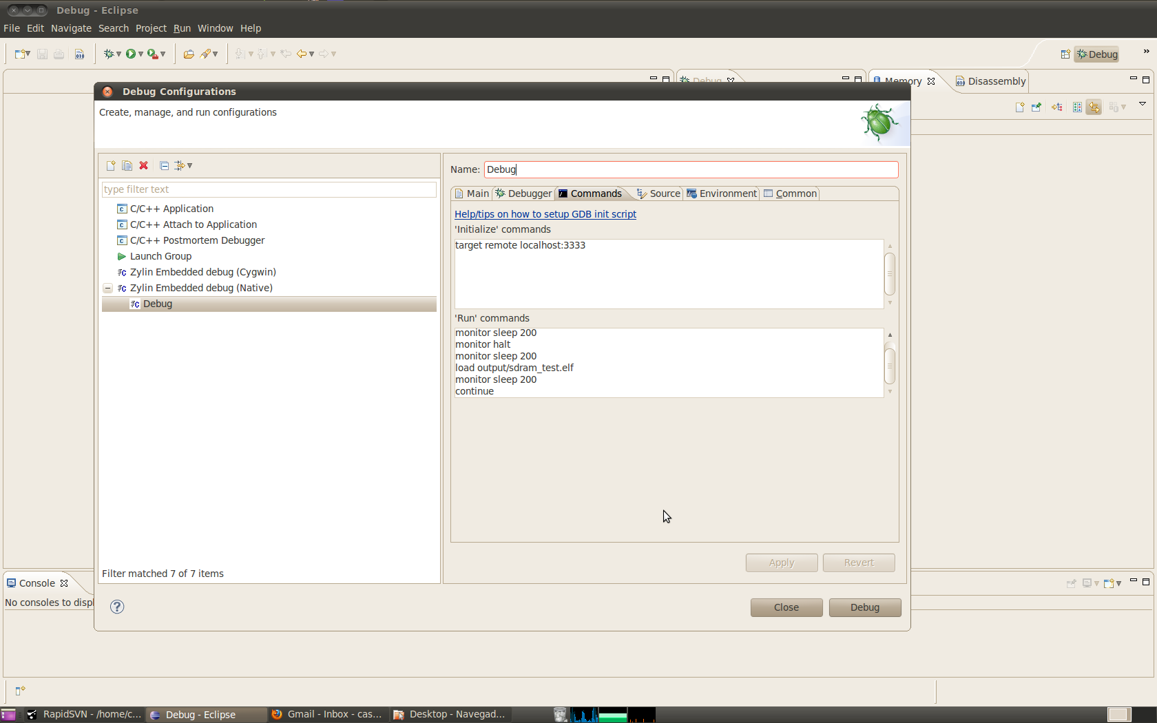
Second, I connect the JTAG cable and execute "OpenOCD" on Eclipse. If
you import on Eclipse the "sdram_test" project/folder of code that are
on SVN, you will have an "OpenOCD" and "Debug" entry on Eclipse menus.
You may need to adapt the paths to OpenOCD and arm-none-eabi-gdb.
So, first execute OpenOCD, here it never fails, always connects and
you should see this:
http://www.flickr.com/photos/43558168@N00/4669023634/sizes/l/
If OpenOCD/JTAG connection is wrong, like imx233 mux pins not
configured, you should see this error:
http://www.flickr.com/photos/43558168@N00/4657201688/sizes/l/
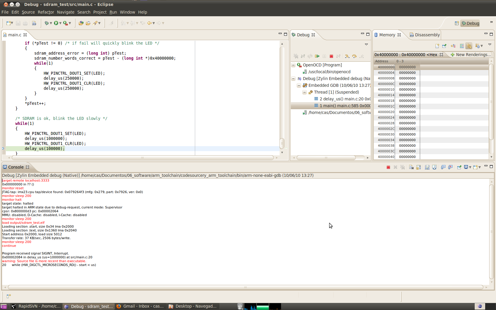
After, click on "Debug" and you should see something like this:
http://www.flickr.com/photos/43558168@N00/4675375577/sizes/l/in/photostream/
But some other times it fails a lot and you will see this:
http://www.flickr.com/photos/43558168@N00/4675375235/sizes/l/
On that times, I just try to do "Debug" a few more times, and/or
connect again the OpenOCD, trying to restart everything.
I hope you can get it, just tell when you get the SDRAM working :-)
To resume, very first I had a bad solder on imx233 pin for the L of
the DC-DC. Then I also had bad solder on some imx233 pins that are
wired to SDRAM.
Casainho
> http://search.digikey.com/scripts/DkSearch/dksus.dll?Detail&name=NHD-2.4-240320YF-CTXI%23-T-1-ND
>
> It has been obsoleted and does not have the same pinout as the LCD
> the PROpendous is targeted for:
> http://search.digikey.com/scripts/DkSearch/dksus.dll?Detail&name=NHD-2.4-240320SF-CTXI%23-T-ND
I think is important that we go now with the same LCD. In future I
would like to make a smaller player, with a smaller LCD and more low
power.
So, I would like one LCD: NHD-2.4-240320SF-CTXI#-T
Also, if an hot glue gun, will be ok for glue the LCD to PCB? instead
of that epoxy? - just because I have already in house and I use that
hot glue.
For solder the LCD contacts that are hold by poliamide, do I need some
low power/temperature iron? because I do not have such iron...
> If you want I can buy all the necessary LCD components and then ship
> them to you. I need some prototyping products from DigiKey but have
> not needed enough parts to justify an order.
Yes, and I guess Bob too, right Bob? And if you buy 3 LCDs, then
shipping may be free for you, which is important.
So, I would like also to try the audio, touchscreen and accelerometer.
I will try to assembly their components and see if some capacitor or
resistor are missing. Like there was at least one resistor you didn't
send, the one of 0.1R. Also I have not enough 33uF capacitors.
I am not sure I will be able to solder the accelerometer with iron.
Also I don't know if is useful for audio player. Maybe not even for a
console, since we are looking always for the LCD at same direction...
Matt, what will you do next, after having SDRAM working? I were
talking with Bob, and we will try the LCD, audio and buttons. Just
after that we may port Rockbox to it. And you? will you try Linux?
Android?
For buttons, do you know some good if we want to use them? like some
buttons more soft to press? I would love to make an enclosure and
buttons just like Gameboy :-)
Casainho
you can make the "Arduino V3".
I think this board is cheap!! Arduino Mega for example, costs more then $60!!
If this board were a bit small/less components as the big SDCard,
audio, video, LCD, touchscreen, accelerometer, serial JTAG, but
continue with the 0.1'' expansion header, it would be a great
"Ardinux" (Arduino + Linux).
This board is great, because it have a powerfull ARM, is DIY and OpenSource.
I would make some tutorials with Linux for it, and some useful sample
programs to control the IOs, try to do examples to access low level
pins.
Many people are using Arduino Mega because of it many IO pins. I would
make a shield with serial/IOs for this imx233 baord.
Matt, plan the future and be careful with the licenses, choose
something like Arduino, at least you could win selling the assembled
and tested board + shields.
Bob
handshaking on the UART. It will just send bits into the ether.
On 9 June, 16:25, Casainho <casai...@gmail.com> wrote:
> On Wed, Jun 9, 2010 at 4:02 PM, Opendous Support
>
Casainho
<opendous...@gmail.com> wrote:
> Casainho,
>
> This is a big email so thanks in advance for your patience.
>
> I managed to get JTAG working. It turns out I forgot to set the
> USE_PARALLEL_JTAG fuse in HW_OCOTP_CUSTCAP. I only set the fuses in
> HW_OCOTP_ROM0.
?? so, you mean that the blink_LED code needs also to enable that fuses?
Well, for future, I would prefer to avoid using the Windows BitBurner
and enable instead the bits using a boot image. Anyway, later we can
work more on this.
> Also, PSWITCH does not behave the same as SRST. It is not an
> active-low RESET switch. Bend the SRST pin down on the PROpendous
> JTAG header so that it is not used. Also, set reset_config in
> imx233.cfg to trst_only. This will fix the random connection problems
> you are having.
Ok! Thanks, I think I understand now the reset of JTAG and reset of
imx233. I think JTAG were expecting to maintain the imx233 in reset
state while reset line is low, but it can just do reset when goes to
low, if time < 10ns.
I did removed the capacitor on pswitch pin, but even like that I can't
do reset to imx233 using the button!! I verified on oscilloscope, time
is a few us!
Maybe set reset_config trst_only is enough for JTAG cable not use
pwsitch pin, and no need to bend that pin on JTAG connector? -- I will
test this idea.
> I am still having problems with your SDRAM Testing code.
> Debug.launch did not import properly and I get Error.jpg with my
> custom debug configuration.
1st: looks like you are using an different Eclipse/ZylinCDT plugin.
2nd: you are using arm-linux toolchain while I am using arm-none-eabi,
from: http://www.codesourcery.com/downloads/public/public/gnu_toolchain/arm-none-eabi
I am sending pictures of all so you can compare. And I did commit all
the code, included builded files. Also a picture from SVN where you
can see all project files of Eclipse.
>>Also, will a hot glue gun be ok to glue
>>the LCD to a PCB instead of that epoxy?
>
> It is too weak.
Too week? you mean that it do not glue very well to PCB? -- because I
am afraid that after I can't remove the LCD from PCB, If I need. If
using hot glue, I can easily remove with hot hair dryer.
Just go to your local hardware store and buy some
> cheap 5-minute 2-part epoxy: Epoxy.jpg. You might be interested to
> know that this is the sort of epoxy used with carbon fiber, if you
> ever want to pursue that sort of an enclosure which is what I am
> considering as I do not have an extruder. Also, does Hammond provide
> enough data for you to recreate their case?
Hammond provide some 3D files that I couldn't open. I am using
Blender... I even searched a bit about this but couldn't get any
solution. I did this when you first told me about this files shared by
Hammond :-)
I am working on my 3D printer, and I think Bob and you may go ahead
with firmware. I think that printing enclosures (if with good quality)
are very important to the success of this project.
>>to solder the LCD contacts that are hold by polyimide
>>do I need a low power/temperature iron?
>
> Polyimide is the same material used for flexible PCBs and for
> masking during reflow. It will withstand your standard iron for a few
> seconds.
> http://www.instructables.com/id/DIY-Flexible-Printed-Circuits/
> http://search.digikey.com/scripts/DkSearch/dksus.dll?Detail&name=47027-ND
Nice to know, thanks.
>>There was at least one resistor you didn't send, the 0.1R one
>
> The 0.1R resistor was supposed to be used to increase the ESR of one
> of the bypass caps but the cap already has higher ESR. Just use a
> 0-Ohm or similar.
Ok, I will :-) (however my board and Bob one, are working without this
resistor).
Take a look at the schematic in
> PROpendous-Power_Boot.pdf, A5, VDD4P2 filter. I will send you another
> one as I bought the 1206 version by accident last time.
>
>>Also, I did not have enough 33uF capacitors.
>
> DigiKey sent me the wrong 68uF caps so I sent you other caps instead.
Nice that board even worked without that capacitor. Well, I think I
used some of 22uF, you know, you sent me a lot of components and I
used what I had :-)
Casainho
<opendous...@gmail.com> wrote:
> Casainho,
>>>Are you using HW_PINCTRL_DRIVE4 for JTAG pin control? It is
>>>HW_PINCTRL_DRIVE8 that contains the SSP1/JTAG pins:
>>>HW_PINCTRL_DRIVE8_CLR(0xFFFFFFFF);
>>>HW_PINCTRL_DRIVE8_SET(0x22222202);
>>No, I think you are mistaken. Verify again the datasheet.
>
> The MUX register is HW_PINCTRL_MUXSEL4, Pg#1425, but the Drive
> register for controlling the SSP1/JTAG pins is HW_PINCTRL_DRIVE8,
> Pg#1466. HW_PINCTRL_DRIVE4 controls the LCD pins, Pg#1460. All this
> means you might have been driving the pins at 4mA instead of 12mA.
> Since it works that means the design is more EMI tolerant, so good.
> But, the OTP bits set JTAG to 12mA so the drive strength setting may
> not make any difference.
You are correct! And yes, I have also the fuses enable for this.
And I thought I had commit the blink LED code but I didn't for most of
files. Now I did :-)
>>For buttons, do you know of some good ones?
>>I like buttons that are soft to press
>
> I have had a lot of success with the Panasonic EVQ buttons. They
> reflow well, are very reliable, and come in a wide range of operating
> forces. 160gf gives a good snap whereas 50gf is very light.
> http://search.digikey.com/scripts/DkSearch/dksus.dll?vendor=0&keywords=EVQ-Q2
Thanks! By the way, do you know that there is a script for Firefox
that let us select over price!!
http://hackaday.com/2010/05/11/digikey-sort-by-price-script/
>>Actual board is a bit large, so, the 2.4'' LCD will be ok.
>
> The 2.4" LCD is 61x43mm whereas the Hammond 1553B_BAT PCB is 78x54mm
> (54mm if you mount the LCD inside the case and want to avoid the screw
> pillars). There is not that much room left over.
Nice :-)
>>Later I would prefer to make the nano concept.
>
> Without moving to smaller parts and more layers I do not see how you
> could fit the design in a smaller area. Notice every bit of room is
> used in my design. There is no usable free space. Even if you remove
> the Video port and USB-A connector and shrink the expansion header you
> still cannot reduce the board size by much. Removing the LCD
> connectors would at most shave 0.5cm off the width. Note the Chumby
> is as small a design as possible, uses the BGA i.MX233, and is 4x4"
> vs. 4.5x3.1" for the Hammond 1553B (16sq.in vs. 14sq.in).
Ok.
I am
> actually thinking of making the board larger, with 0805 components and
> with components on only one side to make it even more prototyping
> friendly. If it cannot be put together by amateurs then it will fail
> as a DIY project. Even I found the 0603 parts troublesome. I would
> normally reflow a board with parts this small.
You are right! Even 0805 may be problematic. But hey, have have much
luck in having this ARM in LQFP and not BGA :-)
So, you mean you will sell the kit with imx233 soldered on PCB? I
think is a good idea.
>>What will you do next, after having SDRAM working?
>
> I still need to test SDRAM timing as well as the Micron DDR. After
> that I will focus on Linux and the LCD.
Micron DDR? why? what's thatmemory for? do we need it?
And actual memory is of 32Mbytes. Does the imx233 LQFP/board supports
larger memory? I mean, maybe Linux and Android need larger memory,
right?
For Rockbox only, 8Mbytes is ok, but maybe Rockbox will run on Linux,
so, is better to go with the same memory for Linux.
> If you and Bob are able and willing to pay for the LCDs and Micron
> SDRAM then I will go ahead and purchase the items. They are somewhat
> expensive so I want to make sure you and Bob really want them before I
> buy anything.
> http://search.digikey.com/scripts/DkSearch/dksus.dll?vendor=0&keywords=NHD-2.4-240320SF-CTXI%23-T
> http://search.digikey.com/scripts/DkSearch/dksus.dll?Detail&name=557-1212-1-ND
> If you want anything else please let me know. Shipping will be
> about $14 as the package will be heavier this time. I will throw in
> some LPC-related prototype boards to make everything more worthwhile
> for you.
I appreciate but I prefer no, just because I do not have free time to
work with them, meaning it will be a waste of components. For now, I
will focus on this imx233 board :-)
> Also, low ESR tantalum caps are expensive so I am thinking about
> standardizing on one value high quality ceramic capacitor (ceramics
> have negligible ESR). If you plan on making more of these boards in
> the future then let me know if you are interested in buying caps in
> quantity to save on the price.
> http://search.digikey.com/scripts/DkSearch/dksus.dll?Detail&name=399-4695-1-ND
Well, If you do not make an "Arduino Linux" with this board, I hope to
do it, because I need such technology. Maybe with the 0805 components?
john cooper
> I did removed the capacitor on pswitch pin, but even like that I can't
> do reset to imx233 using the button!! I verified on oscilloscope, time
> is a few us!
>
> Maybe set reset_config trst_only is enough for JTAG cable not use
> pwsitch pin, and no need to bend that pin on JTAG connector? -- I will
> test this idea.
The negative pswitch transition preforms a HW disable of
the DC/DC converter, eg: power down vs. a traditional reset. So
register/memory state won't be preserved.
This also requires a <15ns negative transition which is
fairly fast so you could be contending with that constraint.
IIRC there is an OTP option to disable the negative transition
power down ability.
>> I am still having problems with your SDRAM Testing code.
Sorry if I missed it, but have you tried a more aggressive
memory test to detect stuck or shorted data/data, data/addr,
addr/addr lines, correct addr to RAS/CAS mapping? Also
some sort of signal integrity test where addr & data lines
change state as fast as possible, etc.. which is also needed
to optimize EMI timing.
>>> Also, will a hot glue gun be ok to glue
>>> the LCD to a PCB instead of that epoxy?
>> It is too weak.
>
> Too week? you mean that it do not glue very well to PCB? -- because I
> am afraid that after I can't remove the LCD from PCB, If I need. If
> using hot glue, I can easily remove with hot hair dryer.
You might be able to mess with hot glue afterwards but it
obviously isn't going to do much at soldering temperatures.
Removing epoxy is an unhappy experience but you might consider
a common cyanoacrylate adhesive. Assuming it bonds to the
LCD ffc/fpc cable polymer you can dissolve the bond with
a drop or two of acetone fairly easily afterward.
>>> to solder the LCD contacts that are hold by polyimide
>>> do I need a low power/temperature iron?
>> Polyimide is the same material used for flexible PCBs and for
>> masking during reflow. It will withstand your standard iron for a few
>> seconds.
I've had far better luck with an iron vs. hot air with some
ffc/fpc. It is difficult to get the joint mass up to reflow
temperature with hot air and not cook low mass the cable backing.
A hot bar press is typically used to seat these connectors where
sufficient thermal mass exists in the bar head to allow a lower
operating temperature.
When I doubt I still use the ultra-hi-tech technique of a
wet tissue on the cable located as close to the joint as
possible to limit the meltdown.
>>> There was at least one resistor you didn't send, the 0.1R one
>> The 0.1R resistor was supposed to be used to increase the ESR of one
>> of the bypass caps but the cap already has higher ESR. Just use a
>> 0-Ohm or similar.
I'd like to factor out that 100mohm resistor as it is
both rare and overpriced. I was going to just use a
higher ESR tantalum cap in that bypass but case sizes
run rather large and the bottom line cost wasn't much
different. FSL doesn't offer any detail on the
battery charger oscillation issue they're attempting to
suppress so I added it a boilerplate for the time being.
> Ok, I will :-) (however my board and Bob one, are working without this
> resistor).
You probably want at least a 0ohm resistor in there
as it the bypass otherwise is open.
-john
john cooper
> On Thu, Jun 10, 2010 at 12:36 PM, Opendous Support
> <opendous...@gmail.com> wrote:
>> Casainho,
>
>>>> Are you using HW_PINCTRL_DRIVE4 for JTAG pin control? It is
>>>> HW_PINCTRL_DRIVE8 that contains the SSP1/JTAG pins:
>>>> HW_PINCTRL_DRIVE8_CLR(0xFFFFFFFF);
>>>> HW_PINCTRL_DRIVE8_SET(0x22222202);
>>> No, I think you are mistaken. Verify again the datasheet.
>> The MUX register is HW_PINCTRL_MUXSEL4, Pg#1425, but the Drive
>> register for controlling the SSP1/JTAG pins is HW_PINCTRL_DRIVE8,
>> Pg#1466. HW_PINCTRL_DRIVE4 controls the LCD pins, Pg#1460. All this
>> means you might have been driving the pins at 4mA instead of 12mA.
>> Since it works that means the design is more EMI tolerant, so good.
>> But, the OTP bits set JTAG to 12mA so the drive strength setting may
>> not make any difference.
>
> You are correct! And yes, I have also the fuses enable for this.
>
> And I thought I had commit the blink LED code but I didn't for most of
> files. Now I did :-)
>
>
>>> For buttons, do you know of some good ones?
>>> I like buttons that are soft to press
>> I have had a lot of success with the Panasonic EVQ buttons. They
>> reflow well, are very reliable, and come in a wide range of operating
>> forces. 160gf gives a good snap whereas 50gf is very light.
There is also the tradeoff of operation life vs. actuation force.
For a given design, beyond a certain actuation force the
projected life cycle count decreases dramatically. Bare domes
are better in this respect than mounted domes or tact switches
but have their own headaches of requiring nickel/gold contact
plating and a funky adhesive mounting scheme. Domes (mounted
or bare) also need to be actuated in their center via a
probe molded into the keytop.
> Micron DDR? why? what's thatmemory for? do we need it?
I ordered Qimonda (who I've never hear of before) 512mb ddr1 devices
based primarily on price (US$6). I believe the Micron devices may
be more obtainable going forward but Micron isn't shy about
discontinuing products IME.
> And actual memory is of 32Mbytes. Does the imx233 LQFP/board supports
> larger memory?
One ddr device @ 64MB is the limit for the 128 lqfp.
BTW $6/512mb is a steal for DDR1. I was looking for
SDR DRAM for another linux board and the cheapest I
could find was ~US$11 for half that size (256mb),
with 512mb sdram somewhere in the insane US$30 ballpark.
Current popular volumes I suppose. Buy them while they're
in season.
> I mean, maybe Linux and Android need larger memory,
> right?
The linux kernel particularly in an embedded configuration
isn't typically a memory consumption issue. Rather it is a
function of the application. For one data point, at TiVo we
only used 16MB in the series2 DVRs which supported a fairly
heavy weight application. Tests I'd done at the time trying
to assess memory pressure thresholds found only half of memory
in use during normal operation. That however was a VM-enabled
system so there was some fallback if the application footprint
spiked beyond available DRAM -- rare in actual usage.
I can't comment on Rockbox but a self-contained audio decode
application can be fairly lightweight. And I'd expect the
steady-state glibc mapped working set to dwarf the audio
decode app itself.
> For Rockbox only, 8Mbytes is ok, but maybe Rockbox will run on Linux,
> so, is better to go with the same memory for Linux.
8MB? Why so large?
FWIW and given the fact the imx233 started life as Sigmatel's
brainchild I'd hazard a use case existed for a decoder app in
64KB of mask rom and 32MB of SRAM. Just speculation though.
-john
Bob
> One ddr device @ 64MB is the limit for the 128 lqfp.
don't know if that is a practical option, I didn't look into it
further because 64MB is surely plenty...
> > For Rockbox only, 8Mbytes is ok, but maybe Rockbox will run on Linux,
> > so, is better to go with the same memory for Linux.
>
> 8MB? Why so large?
improvement in battery life to buffer SD access. Unless there is a
significant cost reduction, may as well go with a larger size.
Casainho
<opendous...@gmail.com> wrote:
> Casainho,
>
> Thank you very much for the detailed notes. I will try them later today.
>
>>Maybe set reset_config trst_only is enough for
>>JTAG cable not use pwsitch pin, and no need to
>>bend that pin on JTAG connector?
>
> equates to a PSWITCH "High-Level" (>1.75V) signal. A "High-Level"
> PSWITCH during boot will enter the USB bootloader (unless an OTP fuse
> is set to disallow it). A "Mid-Level" PSWITCH (>0.9V, <1.5V) such as
> when the pin is connected to VDDXTAL (this occurs when you press the
> button) is used as a power-up signal when the board is running off
> battery. A <10ns falling edge to "Low-Level" (<0.5V) will cause a
> power-down but only when running on battery and enabled in firmware.
> PSWITCH is not exactly like nSRST. It is connected on the Serial
> Debug Header so I assumed during my designing that it was a RESET-like
> signal.
Ok :-)
>>>[epoxy] is too weak.
>>Too week? you mean that it do not
>>glue very well to PCB? -- because I
>>may want to remove the LCD from PCB
>
> Good point. However, you may want to test any particular epoxy to
> see how well it bonds to polyimide. Or, just buy some polyimide tape
> and use it to keep the LCD connector in place:
> http://search.digikey.com/scripts/DkSearch/dksus.dll?Detail&name=3M1206A-ND
I have plenty of that tape, since it is used a lot on RepRap 3D
printer, to glue nichrome wire on heater element. There is much
cheaper source for that tape here:
http://www.dealextreme.com/details.dx/sku.21359
http://www.dealextreme.com/details.dx/sku.21351
>>>The 0.1R resistor
>>my board and Bob's are working without it
>
> Populate a 0ohm resistor or short the pads. Without it the VDD4P2
> line has no bulk bypass cap and will fail to work properly when
> running off/charging a battery.
Ok.
>>By the way, do you know that there is a script
>>for Firefox that lets you sort over price!!
>>http://hackaday.com/2010/05/11/digikey-sort-by-price-script/
>
> Thanks! I was completely unaware and this which means that the
> DigiKey website now has the best and fastest interface of all the
> electronics suppliers.
>
> Also, were you aware that there is a www.DigiKey.pt? Their prices
> are in euros and include duty charges. 65euro+ orders get free
> shipping. This is even better than the Canadian version which
> requires $200CAD=160Euro orders for free shipping.
>
> By the way, if you and Bob are interested in pursuing the LCD I
> suggest you order the parts from www.DigiKey.pt yourself. The order
> will easily be over 65euro.
Ok, I will. But Digikey is slow to arrive here in Portugal, also
because I need to pay taxes :-(
So, when you have your LCD soldered, please post pictures.
> John mentioned using the TSC2007 vs. the TSC2003 as it is cheaper.
> This is a good idea. The TSC2003 just has a few extra ADC inputs and
> a faster ADC. Either should work well and the board does not use the
> extra TSC2003 functions.
Ok. But for now, you sent me one for me and other for Bob.
>>so, you mean you will sell the kit with imx233
>>soldered on PCB? I think is a good idea.
>
> I really don't know yet. A single-side component board with 0805
> parts would need to be 4-layer. Let us see how the current design
> goes. The next revision will be a simple update to fix the minor
> errors such as the USB switch.
One thing I think have logic, is to have SDCard on actual place of
uSDCard and vice-versa, and default booting from uSDCard. Because
imx233 could boot and enable JTAG, disable then the uSDCard and let us
debug with SDCard working, not right now as we "lost" SDCard when
doing debug.
Also I would like to know what expansion system could be added. Is
there one SPI available? Arduino have IO pins, PWM, ADC, SPI and I2C.
I think SPI and I2C is a way to expand the hardware (not considering
the USB).
Maybe an IO expander shield could be done using SPI or I2C. The same
for PWM and ADC.
Maybe would be better if in the place of LCD pins, a 0.1' header
existed. Not all applications may need the LCD. And maybe the LCD
could be easier to connect on a secondary board.
And I can't find on market a battery for the used connector...
So, let's stay a while with this board :-)
And about the 0805 option, why not components on both sides? I think
people can solder easily on both sides! Or is easier for you to
assembly and use the oven?
Next boards, I hope you get some more and start marketing them!
>>>I still need to test ... the Micron DDR.
>>Micron DDR? why? what's that memory for? do we need it?
>
> The Winbond memory we are currently using has been obsoleted and
> Micron is the only company that has long term support for product
> lines. They charge more for their products as a result.
Hmmm, ok.
john cooper
> On 10 June, 20:15, john cooper <john.coo...@third-harmonic.com> wrote:
>> One ddr device @ 64MB is the limit for the 128 lqfp.
>
> In theory, we could use 128MB if we have two 64MBx8 devices but I
I didn't think so but after having another look it
may well be. Referencing the Micron MT46V* data,
x8 wide versions grow a discontiguous A11 in addition
to the A0-A9 column addresses which is just within
the map of the controller, DQS/DM are routed to
their separate byte lanes. Should "just work".
> I didn't look into it
> further because 64MB is surely plenty...
A decade ago I lived quite happily with a FreeBSD
whitebox sporting a 200Mhz Cyrix and 64MB of SDRAM.
I couldn't even install a contemporary Linux release
on anything close to that, let alone getting far enough
along using the install to become a dissatisfied user.
>>> For Rockbox only, 8Mbytes is ok, but maybe Rockbox will run on Linux,
>>> so, is better to go with the same memory for Linux.
>> 8MB? Why so large?
>
> A larger RAM size is useful on HDD devices, it may give a small
> improvement in battery life to buffer SD access. Unless there is a
> significant cost reduction, may as well go with a larger size.
For SD I wouldn't expect a power savings. But probably so
for the case of a HDD assuming the disk can be spun down.
Ignoring metadata 1MB holds over a minute of audio
data compressed @ 128kb/s. To get the disk to spin down
reliably, you'd need to assure the root wasn't on the HDD
(which may be a non-issue here).
-john
john cooper
> <opendous...@gmail.com> wrote:
>> John mentioned using the TSC2007 vs. the TSC2003 as it is cheaper.
>> This is a good idea. The TSC2003 just has a few extra ADC inputs and
>> a faster ADC. Either should work well and the board does not use the
>> extra TSC2003 functions.
The greater concern is the 2003 may not be able to sample
the touchscreen at a sufficiently high rate to satisfy the
user when limited by a 400Khz i2c bus clock limit. The 2007
does data oversampling/averaging which offloads the bus
(and SoC for that matter) considerably.
I don't know why they didn't consider a 144 pin package for
the lqfp as that would have resolved some of this functionality
lost to available pins.
-john
john cooper
> I am not sure I will be able to solder the accelerometer with iron.
> Also I don't know if is useful for audio player. Maybe not even for a
> console, since we are looking always for the LCD at same direction...
That's something I keep meaning to ask -- what is the planned
use for the accelerometer? My first thought was as a contingency
for a navigation app, but as above perhaps just for maintaining
display heads-up orientation?
-john
Bob
> That's something I keep meaning to ask -- what is the planned
> use for the accelerometer? My first thought was as a contingency
> for a navigation app, but as above perhaps just for maintaining
> display heads-up orientation?
I have an auto portrait/landscape on my phone but I might have to turn
to off. Walking, talking and also having to think about exactly how I
am holding my phone puts my poor old brain into overload. ;)