Display Board Problem
173 views
Skip to first unread message

Tom Moll
Jan 19, 2022, 9:22:49 PM1/19/22
to RFPowerTools Forum
I've been chipping away at building the amp, and am making good progress.
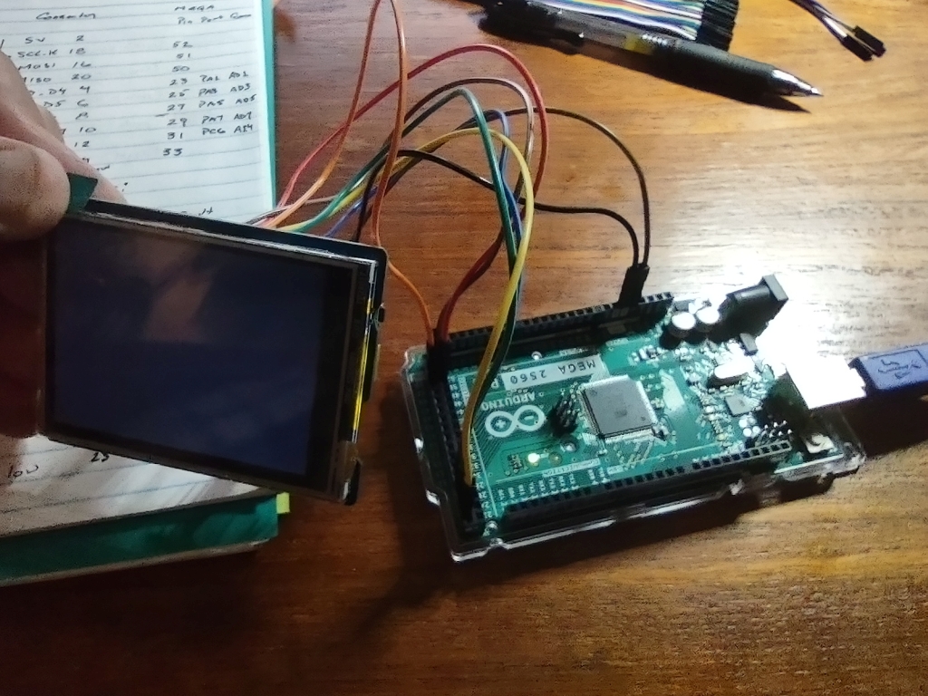
I am at the stage of incrementally testing the sub assemblies, and have the following boards connected: Control Board; LPF Board; TR Board: and Display Board.
I have compiled the code and loaded it onto the MEGA 2560. Basic checks indicate that is is working as expected as pushing the band select switch cycles the relays on the LPF Board, asserting PTT causes the TR switch to activate and the multi-color LED on the display board to change from green to red. So the program is alive and well.
However, the LCD display is not working - on power up it comes on and displays a bright white square that covers the entire LCD, but the display text or graphic widgets are never displayed on it. Information on the Waveshare display is limited. It kind of looks like the brightness may just be maxed out, but it doesn't appear that there is a brightness control (unless it's software controlled - don't see anything in the code).
I have double checked the interconnect wiring and am confident it is right. I have used both a ribbon cable interconnect as well as individual wires with the same result.
I vaguely recall a conversation about the ferrite beads on the control lines being a possible problem (???). Any ideas or suggestions on how to further troubleshoot this?
I could write a test program that just exercises the display and see how that behaves I guess, but I have no reason to believe the control program isn't working properly since other functions work.
Tnx, Tom N0BS

jcve...@gmail.com
Jan 19, 2022, 10:15:08 PM1/19/22
to RFPowerTools Forum
Hi Tom,
73,
Jim WA2EUJ
Tom Moll
Jan 20, 2022, 12:02:43 PM1/20/22
to RFPowerTools Forum
Hi Jim, thanks for the quick reply. I was unaware of the jumper requirement on the back side - will need to check that out - could well be the issue.
Unfortunately, I soldered the display in place as I had no headers that were low profile enough to socket the display and still have the 4 buttons
protrude far enough for ultimately packaging the display - so I made the tactical (bad) decision to solder in place. I'll have to see if I can remove it
and start over. If I can get it off I will socket it and just abandon the switches in favor of touch screen buttons I guess. The library for this display
seems pretty rudimentary - maybe there is a more highly developed library that works with it - need to search for one. I had developed a whole bunch
of graphic widgets incorporating the touch screen for an ILI9341 LCD touchscreen (uses same touchscreen controller) for a different project using a Teensy, so
maybe I can port those over to this display. I'll keep working the problem! I am having fun and learning.
73, Tom N0BS

Andy Hecker
May 2, 2023, 10:43:38 PM5/2/23
to RFPowerTools Forum
Greets All,
I'm at the same point with the 'original' controller (Control Board Ref A) Tom was last year. I get a blank screen, a lit backlight, and no data on the LCD. I've changed the init line in the code to display colors other than gray - it appears the LCD is not getting the initialization command or anything else.
Wiring is good and per the schematic. The Arduino is reading switch presses and toggling the lines for the low-pass filters, so the Arduino seems to be happy. The CS is pulled low and data flows to the LCD. The attached image is the CS, MOSI, and MISO data captured at the pins for the display.
When I remove the 3x 0 Ohm 'resistors' from the back of the LCD, plug it into the Arduino, and run the WaveShare demo programs, they all run as expected.
Has anyone gotten the "Control Board Rev A" to write to the LCD? If so, would you care to share the secret?
Thanks and 73,
Andy
KG5RKP/MM

Patrick Murphy
May 3, 2023, 7:29:06 AM5/3/23
to RFPowerTools Forum
Those jumpers can be a problem if you don't have 0 ohm resistors available. Scraps of flat terminal pins work well.
See https://groups.google.com/g/hardrock-500-technical-forum/c/4BGH9ezUSb4/m/70D547tSBQAJ for my testing procedure.
Patrick
AC1KM
Andy Hecker
May 3, 2023, 12:47:18 PM5/3/23
to RFPowerTools Forum
Hi Patrick,
Thanks for the heads-up about the jumper, and also for the link to the other group. I'll spend some time reading there. I have added and replaced the 0 Ohm resistors at SB1, 2, and 3, and have continuity between SCLK, MISO, and MOSI between the pins on the display and the ICSP socket.
I've built a number of Arduino and Teensy controllers (scratch and kit) with 2- and 4-line displays, and a couple of different LCDs (Nextion, ILI9341). Connect the wires, load the software, and they "just work". This is making my head hurt! hihi
Thanks to Bob, WA2T for reminding me about the ferrite beads on each side of the cable on the display and control boards - I'm sorry my initial post was incomplete. I initially built the board using the FBs, but replaced them with 0 Ohm resistors on Jim, WA2EUJ's advice.
Thank you very much for confirming that the controller and display can work!
73, Andy
Andy Hecker
May 3, 2023, 3:09:44 PM5/3/23
to RFPowerTools Forum
Quick follow-up.
Only one FB remains between the LCD and Arduino Mega 2560 R3 (official Arduino) - FB12 on the control board (the backlight control line). The backlight does work when the board is powered up.
I've verified continuity on the back of the WaveShare LCD between the SPI and CN7 - the SB1, SB2, and SB3 jumpers are in place and have good connections.
I've verified all of the lines between the Arduino and the LCD - end to end. The logic analyzer shows the CS going low and data flowing. The attached logic analyzer image is captured at the pins for the LCD and starts before the controller is connected to 12 VDC.
There was a file name problem with the supplied Arduino files. The (heavily modified) library files contain "RPT_COLOR_LCD.H", and there's a file with the same name in the Arduino code base. I had to rename the .h in the code base and edit the include line in order for the code to compile. I'm using a fresh install of the V1.8.19 Arduino IDE. I get four warnings but the code compiles.
Does any of this sound familiar to folks using this controller?
Thanks all,
Andy
-----------
C:\Users\Andy\Documents\Arduino\100W_Controller\Serial_Proc.ino: In function 'void uartGrabBuffer()':
C:\Users\Andy\Documents\Arduino\100W_Controller\Serial_Proc.ino:11:18: warning: invalid conversion from 'const char*' to 'char' [-fpermissive]
lastChar[0] = "C";
^~~
C:\Users\Andy\Documents\Arduino\100W_Controller\Serial_Proc.ino: In function 'void uartGrabBuffer2()':
C:\Users\Andy\Documents\Arduino\100W_Controller\Serial_Proc.ino:29:18: warning: invalid conversion from 'const char*' to 'char' [-fpermissive]
lastChar[0] = "C";
^~~
C:\Users\Andy\Documents\Arduino\100W_Controller\Serial_Proc.ino: In function 'void findBand(short int)':
C:\Users\Andy\Documents\Arduino\100W_Controller\Serial_Proc.ino:104:28: warning: invalid conversion from 'uint8_t* {aka unsigned char*}' to 'char*' [-fpermissive]
UART_send(uart, (uint8_t *)"HRBN");
^~~~~~~~~~~~~~~~~
C:\Users\Andy\Documents\Arduino\100W_Controller\Serial_Proc.ino:130:6: note: initializing argument 2 of 'void UART_send(char, char*)'
void UART_send(char uart, char *message){
^~~~~~~~~
----------
Andy Hecker
May 4, 2023, 12:28:41 AM5/4/23
to RFPowerTools Forum
I removed the Arduino Mega and LCD from the controller and display boards and wired them per the schematic (which matches the PCB layouts). The behavior is the same: Backlight is lit but there's no display. I think this rules out a hardware problem.
Would anyone with a working controller care to share their code? I don't even know where to start.
Thanks,
Andy
Andy Hecker
May 5, 2023, 3:22:51 AM5/5/23
to RFPowerTools Forum
It appears that the original control and display boards are about three years old. When developed, the WaveShare 2.8" TFT shield used an HX8347 controller for the display. About 2-2.5 years ago, WaveShare upgraded the displays to version 2.1, and changed to an ST7789 controller chip.
It also appears that the controller software used a heavily edited version of the standard lcd library as the basis for the RPT_COLOR_LCD.h and .cpp files. While the configuration info was retained for the HX8347, the parts of the library used to communicate with the ST7789 were removed. While the code would work for those with early displays, anyone using a V2.1 shield was out of luck.
I managed to re-work the software this evening and made some progress. As you can see from the photo, the Arduino is talking to the V2.1 WaveShare display. The LCD is plugged into the display board, and the Arduino is seated into the controller board. I'm not yet sure why the right side of the display is missing. I guess that'll be the next "learning opportunity". First...celebratory rum (I'm on a sailboat, after all!) and sleep.
73, Andy
Andy Hecker
May 5, 2023, 11:23:54 PM5/5/23
to RFPowerTools Forum
Even with the default WaveShare libraries, the WaveShare 320x240 display acts like a 240x240 when rotated 90 degrees into landscape mode. Even when the screen size is explicitly defined, the code or driver or controller seems to be ignoring the additional real estate. I'm also having trouble simply changing the background color. There does appear to be a small amount of development work on a 'proper' library for displays with the ST7789V, but they're still pretty crude.
I'm leaning towards finding a well supported LCD and trying to recreate the meter layout for it so I can at least use the control boards I have. In the mean time, this display works well enough that I can test my other boards - that's a 'win' in my book.
I'll share the files I have if anyone wants to take a stab at it.
73, Andy
Andy Hecker
May 6, 2023, 5:00:43 PM5/6/23
to RFPowerTools Forum
I've had a request for the code, so will post it here. It's Jim's code with updates for the display. The display boxes are moved to fit onto the 240x240 usable display...except for the graph, which cuts off at 80W. It's kind of ugly (the code and display). There might be artifacts on the screen. I haven't yet seen the SWR values display, but they should be in or at least near the correct box. It's functional but could use some massaging by a real programmer, especially if they know how to sweet talk the ST7789V into using all of the display.
I've purchased a 320x240 display with an ILI9341 and touch capability. It's a landscape display by default - no need to rotate either the LCD or touch code. I've used it with Arduino and Teensy SBCs (and in a number of µBITX radios) and it works well. I'll see if I can get this display to work right in 320x240. At about $17 from Amazon and less from ebay, it's a more budget friendly display as well.
73, Andy
Reply all
Reply to author
Forward
0 new messages