Need I2C and SPI sample code ?
722 views
Skip to first unread message

Marco Maccaferri
Mar 20, 2021, 12:37:01 PM3/20/21
to retro-comp
Hi,
I wrote a couple of sample programs to test the I2C and SPI devices and
tought of sharing in case they may be useful to someone else.
In the attached ZIP file I have included:
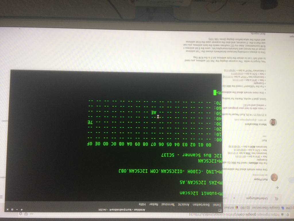
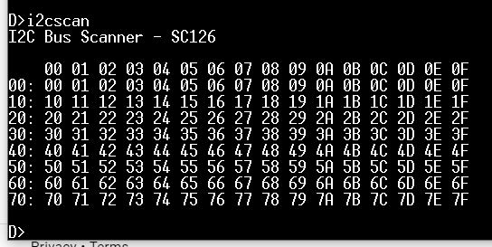
I2CSCAN.AS - I2C Bus Scanner, similar to Linux's i2cdetect shows the
address of the connected devices.
LCD.C - Simple demo to write text to a 16x2 characters LCD with PCF8574.
Prints a message and the current date and time (CP/M 3, not sure what
prints with CP/M 2).
PN532.C - Simple demo to read the tag id from a PN532 NFC device, with
variants for I2C and SPI.
All sources can be compiled with the HI-TECH C compiler, I have recently
discovered there is an active GitHub repository with some updates so I'm
also testing it. https://github.com/agn453/HI-TECH-Z80-C
The source should work with SC126 and SC137 but since I don't have these
boards I can't test them so I haven't included any executable file.
Note: the PN532 is a bit awkward to handle, I2C requires clock
stretching or big delays somewhere, I haven't figured out where to put
them exactly, I had it working initially when printing each received
byte as debug, without it I wasn't able to make it work. The SPI
interface has a glitch with the Z180 CSIO interface as it seems that it
is off-sync by one bit when receiving, bit 7 of the last received byte
is bit 0 of the next. Not a big problem in this case because the PN532
sends data as packets and the first and last bytes are always zero, the
SPI.AS code does a shift to realign the bits.
Enjoy!
Best regards,
Marco
I wrote a couple of sample programs to test the I2C and SPI devices and
tought of sharing in case they may be useful to someone else.
In the attached ZIP file I have included:
I2CSCAN.AS - I2C Bus Scanner, similar to Linux's i2cdetect shows the
address of the connected devices.
LCD.C - Simple demo to write text to a 16x2 characters LCD with PCF8574.
Prints a message and the current date and time (CP/M 3, not sure what
prints with CP/M 2).
PN532.C - Simple demo to read the tag id from a PN532 NFC device, with
variants for I2C and SPI.
All sources can be compiled with the HI-TECH C compiler, I have recently
discovered there is an active GitHub repository with some updates so I'm
also testing it. https://github.com/agn453/HI-TECH-Z80-C
The source should work with SC126 and SC137 but since I don't have these
boards I can't test them so I haven't included any executable file.
Note: the PN532 is a bit awkward to handle, I2C requires clock
stretching or big delays somewhere, I haven't figured out where to put
them exactly, I had it working initially when printing each received
byte as debug, without it I wasn't able to make it work. The SPI
interface has a glitch with the Z180 CSIO interface as it seems that it
is off-sync by one bit when receiving, bit 7 of the last received byte
is bit 0 of the next. Not a big problem in this case because the PN532
sends data as packets and the first and last bytes are always zero, the
SPI.AS code does a shift to realign the bits.
Enjoy!
Best regards,
Marco

Kurt Pieper
Mar 21, 2021, 9:35:48 AM3/21/21
to retro-comp
Hello Marco,
greetings to Italy.
I was able to test your program with the SC22C (20Mhz CPU on rc2014 series) and sc137.
It works. Thanks for the program.
I mainly work with z80asm. I'm still in the learning phase.
We never stop learning.
Sometimes also with C Vers. 1.06D 8080 (C) 1982 1983 1984 by Manx Software System.
It was on my list - but now you've already written it. Great.
greetings from Germany
Kurt
Kurt Pieper
Mar 21, 2021, 9:58:27 AM3/21/21
to retro-comp
One more remark about the addresses.
For the z80asm I need the 8Bit i2c address
Example:
hex = 3FH is bin = 0111111
becomes hex 7FH is bin 1111110
hex = 57H is bin = 01010111
becomes AEH is bin = 10101110
Kurt
For the z80asm I need the 8Bit i2c address
Example:
hex = 3FH is bin = 0111111
becomes hex 7FH is bin 1111110
hex = 57H is bin = 01010111
becomes AEH is bin = 10101110
Kurt
Marco Maccaferri
Mar 21, 2021, 11:37:25 AM3/21/21
to retro...@googlegroups.com
Il 21/03/21 14:35, Kurt Pieper ha scritto:
> I was able to test your program with the SC22C (20Mhz CPU on rc2014
> series) and sc137.
Good, glad it works, thanks for testing.
> One more remark about the addresses.
>
> For the *z80asm* I need the 8Bit i2c address
Yes, forgot to write. The scanner display the 7bit I2C address, you need
to shift left 1 bit to obtain the byte address, bit 0 is the R/W flag.
This is always confusing because datasheets shows the 7 bit address
(most of the times) and tutorials/examples/etc. uses the 8 bit address +
R/W (sometimes). Also my I2C routines needs the byte address, you can
see that in the .C sources, and also the scanner uses the 8 bit address
and shifts the value before display (lines 106-109).
Best regards,
Marco
> I was able to test your program with the SC22C (20Mhz CPU on rc2014
> series) and sc137.
> One more remark about the addresses.
>
> Example:
> hex = 3FH is bin = 0111111
> becomes hex *7FH* is bin 1111110
> hex = 3FH is bin = 0111111
> hex = 57H is bin = 01010111
> becomes *AEH* is bin = 10101110
Yes, forgot to write. The scanner display the 7bit I2C address, you need
to shift left 1 bit to obtain the byte address, bit 0 is the R/W flag.
This is always confusing because datasheets shows the 7 bit address
(most of the times) and tutorials/examples/etc. uses the 8 bit address +
R/W (sometimes). Also my I2C routines needs the byte address, you can
see that in the .C sources, and also the scanner uses the 8 bit address
and shifts the value before display (lines 106-109).
Best regards,
Marco
Kurt Pieper
Mar 21, 2021, 12:12:29 PM3/21/21
to retro-comp
Hello Marco,
thanks for the information.
I commented out the line.
4: ld a, (addr) <
ld c, a <
; srl c <
call _hexout
I no longer need my Arduinio for this task.
Greetings from the Rhine
thanks for the information.
4: ld a, (addr) <
ld c, a <
; srl c <
call _hexout
I no longer need my Arduinio for this task.
Greetings from the Rhine
Kurt
Kurt Pieper
Mar 21, 2021, 1:37:33 PM3/21/21
to retro-comp
Now I got curious and installed the HI-TECH Z80 C compiler. Unfortunately, the files were all written in capital letters. The C compiler under CPM3 does not want with div. * .H files.
After converting the * .h files on the Linux side of STD.IO into
std.io had changed and transferred to the cpm system, it also worked.
Unfortunately the file 'DELAY.AS' is missing. LCD needs to be delayed ms. Try to adjust my z80asm delay.z80.
I don't know the HI-TECH-Z80-C-COMPILER yet.
Will deal with this.
greeting
Kurt
Marco Maccaferri
Mar 21, 2021, 1:53:13 PM3/21/21
to retro...@googlegroups.com
Il 21/03/21 18:37, Kurt Pieper ha scritto:
> Unfortunately the file '*DELAY.AS*' is missing. LCD needs to be
files (hopefully). Sorry.
The file contains the 1ms and 100us delay routines, you may need to
adjust the counter values _ms_count and _us100_count to adapt to the
clock speed if you want precise delays.
Best regards,
Marco
> Unfortunately the file '*DELAY.AS*' is missing. LCD needs to be
> delayed ms. Try to adjust my z80asm delay.z80.
Damn... I haven't zipped that file! Attached is the new zip with all
files (hopefully). Sorry.
The file contains the 1ms and 100us delay routines, you may need to
adjust the counter values _ms_count and _us100_count to adapt to the
clock speed if you want precise delays.
Best regards,
Marco
Kurt Pieper
Mar 22, 2021, 7:43:36 AM3/22/21
to retro-comp
Hello Marco,
I have not yet been able to run the LCD program version correctly.
In the program LCD.C I have to enter the Addr: 03FH.
The test is carried out with Z80 CPU 20Mhz and Z80 7.3 ... Mhz.
The 4-line LCD has the address: 027H and the display is here
so displayed.

See photo - LCD clears, but no text display.
All I2C LCD work with the Arduino. stm32 etc.
greeting
Kurt
I have not yet been able to run the LCD program version correctly.
In the program LCD.C I have to enter the Addr: 03FH.
The test is carried out with Z80 CPU 20Mhz and Z80 7.3 ... Mhz.
The 4-line LCD has the address: 027H and the display is here
so displayed.
All I2C LCD work with the Arduino. stm32 etc.
greeting
Kurt
Marco Maccaferri
Mar 22, 2021, 8:17:04 AM3/22/21
to retro...@googlegroups.com
Il 22/03/21 12:43, Kurt Pieper ha scritto:
> In the program LCD.C I have to enter the Addr: 03FH. The test is
> carried out with Z80 CPU 20Mhz and Z80 7.3 ... Mhz.
>
> The 4-line LCD has the address: 027H and the display is here so
> displayed. [image: LCD4.jpg]
>
> See photo - LCD clears, but no text display.
It is possible that the code is missing something, I have tested only
with a 16x2 display.
There are some things to check anyway, some adapters wires the PCF8574
pins differently and may require a change in how the signals are mapped.
I have used this library for Arduino as a reference
https://github.com/mathertel/LiquidCrystal_PCF8574 what library are you
using ? Lines 22-25 maps the signals to the I/O pins, the upper 4 bits
are the data lines.
Best regards,
Marco
> In the program LCD.C I have to enter the Addr: 03FH. The test is
> carried out with Z80 CPU 20Mhz and Z80 7.3 ... Mhz.
>
> The 4-line LCD has the address: 027H and the display is here so
> displayed. [image: LCD4.jpg]
>
> See photo - LCD clears, but no text display.
with a 16x2 display.
There are some things to check anyway, some adapters wires the PCF8574
pins differently and may require a change in how the signals are mapped.
I have used this library for Arduino as a reference
https://github.com/mathertel/LiquidCrystal_PCF8574 what library are you
using ? Lines 22-25 maps the signals to the I/O pins, the upper 4 bits
are the data lines.
Best regards,
Marco
Kurt Pieper
Mar 22, 2021, 11:18:13 AM3/22/21
to retro-comp
Hello Marco,
Thank you for the information. Good work.
This is exactly the information I needed.
The small board from Steve SC407 has an 8574 with ports P1-P8 as well as 5V and GND.
greeting
Kurt
Thank you for the information. Good work.
This is exactly the information I needed.
The small board from Steve SC407 has an 8574 with ports P1-P8 as well as 5V and GND.
greeting
Kurt
Marco Maccaferri
Mar 23, 2021, 8:27:09 AM3/23/21
to retro...@googlegroups.com
Il 23/03/21 12:48, Kurt Pieper ha scritto:
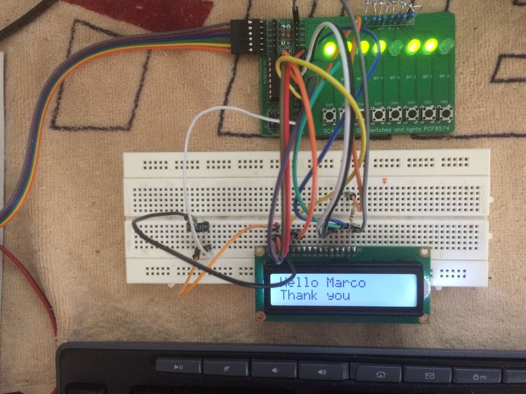
> without words
> [image: Bild5.jpg]
Very good! :-)
Thank you.
Best regards,
Marco
> without words
> [image: Bild5.jpg]
Very good! :-)
Thank you.
Best regards,
Marco
Kurt Pieper
Mar 24, 2021, 10:55:13 AM3/24/21
to retro-comp
I still have two I2C adapters from eHaJo.
I2C uses the PORT's P0 = rs, P1 = rw, P2 = en.
The LCD port control LCD (D4-D7) is controlled from I2C (P3-P6). Software doesn't suit you there.
I haven't found out yet with the Hi-Tech C compiler!
#define PCF_RS 0x00 / * 0x01 * / <
#define PCF_RW 0x01 / * 0x02 * / <
#define PCF_EN 0x02 / * 0x04 * / <
#define PCF_BACKLIGHT 0x08
This has to be changed:
void send (int value, int data) <
{<
sendnibble ((value >> 4 & 0x0F), data); <
sendnibble (value & 0x0F, data)
}
Thanks for some support.
Kurt
I2C uses the PORT's P0 = rs, P1 = rw, P2 = en.
The LCD port control LCD (D4-D7) is controlled from I2C (P3-P6). Software doesn't suit you there.
I haven't found out yet with the Hi-Tech C compiler!
Here are my first attempts:
#define PCF_RW 0x01 / * 0x02 * / <
#define PCF_EN 0x02 / * 0x04 * / <
#define PCF_BACKLIGHT 0x08
This has to be changed:
void send (int value, int data) <
{<
sendnibble ((value >> 4 & 0x0F), data); <
sendnibble (value & 0x0F, data)
}
Kurt
Kurt Pieper
Mar 25, 2021, 11:23:19 AM3/25/21
to retro-comp
Hi, forget the previous picture.
I build myself an I2C-8574 interface
P4-P7 to D4-D7. The SMD is so nice and small.
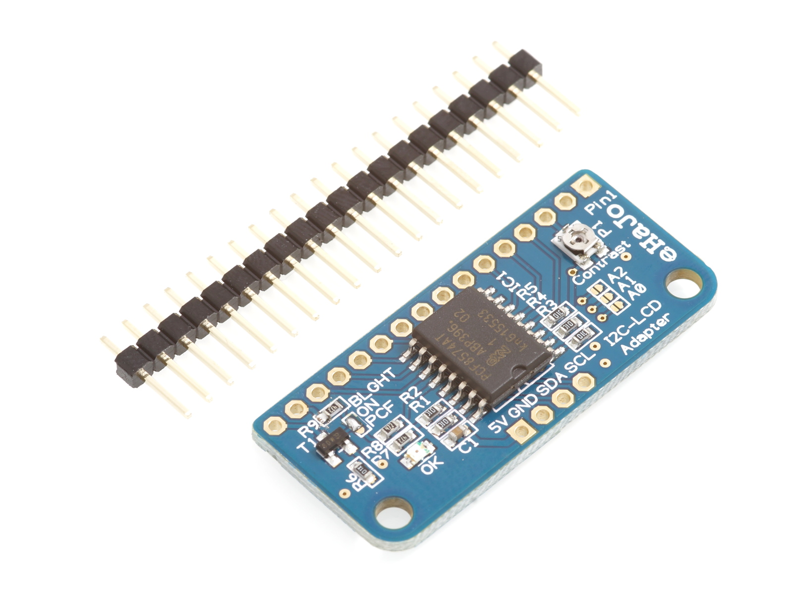
No software needs to be rewritten.
I build myself an I2C-8574 interface
P4-P7 to D4-D7. The SMD is so nice and small.
No software needs to be rewritten.
Kurt
Marco Maccaferri
Mar 25, 2021, 12:07:19 PM3/25/21
to retro...@googlegroups.com
Il 25/03/21 16:23, Kurt Pieper ha scritto:
> Hi, forget the previous picture.
> I build myself an I2C-8574 interface
> P4-P7 to D4-D7. The SMD is so nice and small.
> [image: i2c-lcd-adapter_1.jpg]
> No software needs to be rewritten.
Good, anyway, about the schematic you posted, the changes are not
correct. From the original source, RS, RW and EN are still correct (bits
0, 1 and 2), BACKLIGHT is on bit 7 so change it to 0x80, then the data
bits shift is at line 162, change << 4 to << 3 and it should be done.
Best regards,
Marco
> Hi, forget the previous picture.
> I build myself an I2C-8574 interface
> P4-P7 to D4-D7. The SMD is so nice and small.
> [image: i2c-lcd-adapter_1.jpg]
> No software needs to be rewritten.
correct. From the original source, RS, RW and EN are still correct (bits
0, 1 and 2), BACKLIGHT is on bit 7 so change it to 0x80, then the data
bits shift is at line 162, change << 4 to << 3 and it should be done.
Best regards,
Marco
Kurt Pieper
Mar 26, 2021, 8:12:20 AM3/26/21
to retro-comp
Hello Marco,
First of all, thank you very much for your support.
I had already tried it that way. Without success.
Look at the picture of the free wiring with dm SC407.
There I moved the control lines from P4-P7 to P3-P6.
The control rs, rw, en and bl everything left as it is. Should work like this. Software tested. Unfortunately it does not work.
greeting
Kurt
First of all, thank you very much for your support.
I had already tried it that way. Without success.
Look at the picture of the free wiring with dm SC407.
There I moved the control lines from P4-P7 to P3-P6.
The control rs, rw, en and bl everything left as it is. Should work like this. Software tested. Unfortunately it does not work.
I think the first version works fine. With the module from
https://www.tindie.com/products/tindiescx/sc405-i2c-digital-io-module-kit-pcf8574/?pt=ac_prod_search
it will work.
greeting
Kurt
Marco Maccaferri
Mar 26, 2021, 8:45:42 AM3/26/21
to retro...@googlegroups.com
Il 26/03/21 13:12, Kurt Pieper ha scritto:
> I had already tried it that way. Without success.
>
> Look at the picture of the free wiring with dm SC407. There I moved
> the control lines from P4-P7 to P3-P6. The control rs, rw, en and bl
> everything left as it is. Should work like this. Software tested.
> Unfortunately it does not work.
I don't see how it is wired from the picture, however, if you move the
data lines to P3-P6 and leave the others as they are, it can't work, it
will conflict with backlight which is 0x08 -> P3. You need to move that
too (or set to 0, if you don't need it).
If you use SC407 with its leds, you can easily see how the various
controls are wired. If I'm not wrong, the leds are active low, so the
logic is inverted: on=0, off=1.
Best regards,
Marco
> I had already tried it that way. Without success.
>
> Look at the picture of the free wiring with dm SC407. There I moved
> the control lines from P4-P7 to P3-P6. The control rs, rw, en and bl
> everything left as it is. Should work like this. Software tested.
> Unfortunately it does not work.
data lines to P3-P6 and leave the others as they are, it can't work, it
will conflict with backlight which is 0x08 -> P3. You need to move that
too (or set to 0, if you don't need it).
If you use SC407 with its leds, you can easily see how the various
controls are wired. If I'm not wrong, the leds are active low, so the
logic is inverted: on=0, off=1.
Best regards,
Marco
Kurt Pieper
Mar 26, 2021, 10:10:50 AM3/26/21
to retro-comp
Hello Marco,
I changed your software a bit.
The following program parts have been added to control a 4-line display 20x4.
from int _row_offset [4] to int _row_offset [7];
in function
int main ();
begin (20, 4); <
<
setcursor (0, 0); <
write ("CPU 22C [20 Mhz]"); <
setcursor (0, 1); <
write ("SC137 + SC407");
setcursor (0,2); <
write ("RC2014 Serie 2021"); <
setcursor (0,3); <
write ("SW v. M. Maccaferri");
In this function
void begin (int cols, int lines)
_row_offset [0] = 0x00; <
_row_offset [1] = 0x40; <
_row_offset [2] = 0x00 + cols; <
_row_offset [3] = 0x40 + cols; <
_row_offset [4] = 0x00 + cols; <
_row_offset [5] = 0x40 + cols; <
_row_offset [6] = 0x00 + cols; <
_row_offset [7] = 0x40 + cols; <
<
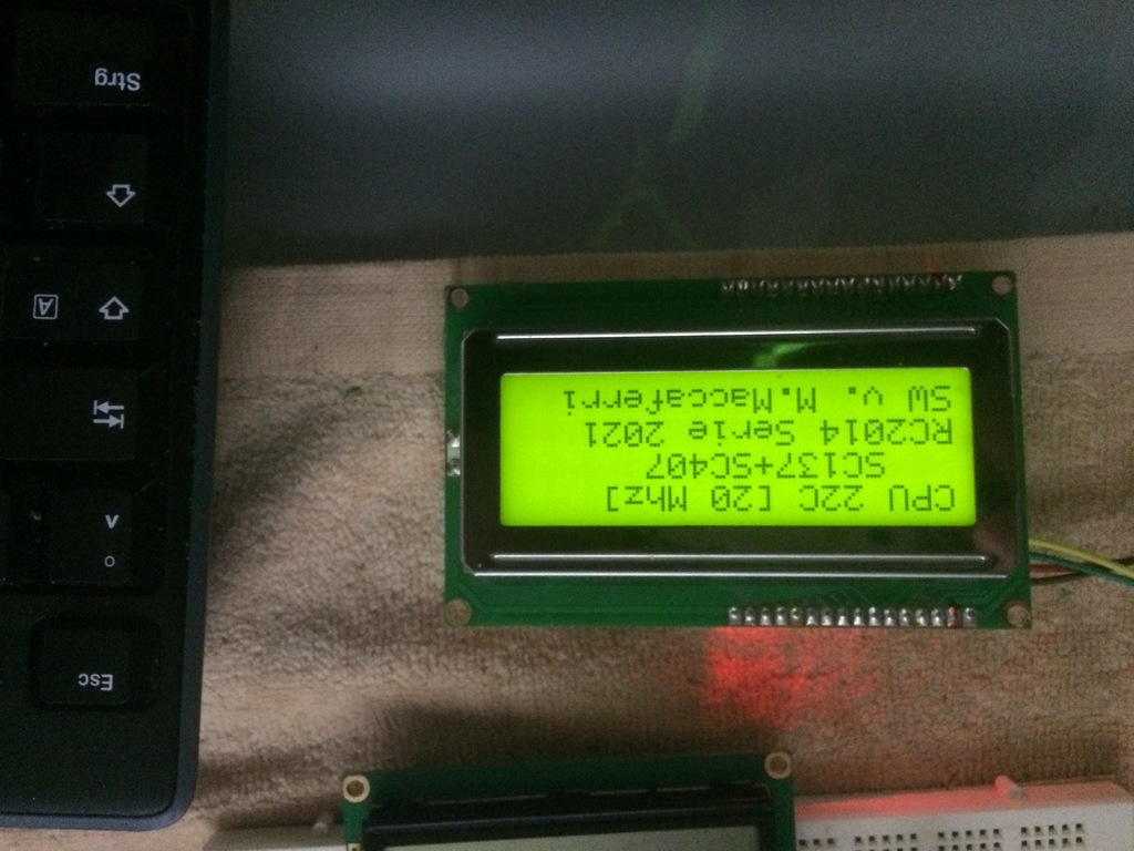
Greetings Kurt
I changed your software a bit.
The following program parts have been added to control a 4-line display 20x4.
from int _row_offset [4] to int _row_offset [7];
in function
int main ();
begin (20, 4); <
<
setcursor (0, 0); <
write ("CPU 22C [20 Mhz]"); <
setcursor (0, 1); <
write ("SC137 + SC407");
setcursor (0,2); <
write ("RC2014 Serie 2021"); <
setcursor (0,3); <
write ("SW v. M. Maccaferri");
In this function
void begin (int cols, int lines)
_row_offset [0] = 0x00; <
_row_offset [1] = 0x40; <
_row_offset [2] = 0x00 + cols; <
_row_offset [3] = 0x40 + cols; <
_row_offset [4] = 0x00 + cols; <
_row_offset [5] = 0x40 + cols; <
_row_offset [6] = 0x00 + cols; <
_row_offset [7] = 0x40 + cols; <
<
See photo
Greetings Kurt
Marco Maccaferri
Mar 26, 2021, 10:45:49 AM3/26/21
to retro...@googlegroups.com
Il 26/03/21 15:10, Kurt Pieper ha scritto:
> I changed your software a bit.
>
> The following program parts have been added to control a 4-line
> display 20x4.
>
> from int _row_offset [4] to int _row_offset [7];
Why ? AFAIK, the code already supported 4 rows.
> in function
> int main ();
> begin (20, 4); <
> <
> setcursor (0, 0); <
> write ("CPU 22C [20 Mhz]"); <
> setcursor (0, 1); <
> write ("SC137 + SC407");
> setcursor (0,2); <
> write ("RC2014 Serie 2021"); <
> setcursor (0,3); <
> write ("SW v. M. Maccaferri");
>
> In this function
> void begin (int cols, int lines)
> _row_offset [0] = 0x00; <
> _row_offset [1] = 0x40; <
> _row_offset [2] = 0x00 + cols; <
> _row_offset [3] = 0x40 + cols; <
> _row_offset [4] = 0x00 + cols; <
> _row_offset [5] = 0x40 + cols; <
> _row_offset [6] = 0x00 + cols; <
> _row_offset [7] = 0x40 + cols; <
The new row_offset elements are never used in your example, maybe with
an 8 rows display (do they exists ?) but still needs to map to something
else and not just duplicate elements 2 and 3. And your last line will
overflow the array, you defined _row_offset with 7 elements but write
into 8th. If this doesn't have side effects and the code works is just luck.
Best regards,
Marco
> I changed your software a bit.
>
> The following program parts have been added to control a 4-line
> display 20x4.
>
> from int _row_offset [4] to int _row_offset [7];
> in function
> int main ();
> begin (20, 4); <
> <
> setcursor (0, 0); <
> write ("CPU 22C [20 Mhz]"); <
> setcursor (0, 1); <
> write ("SC137 + SC407");
> setcursor (0,2); <
> write ("RC2014 Serie 2021"); <
> setcursor (0,3); <
> write ("SW v. M. Maccaferri");
>
> In this function
> void begin (int cols, int lines)
> _row_offset [0] = 0x00; <
> _row_offset [1] = 0x40; <
> _row_offset [2] = 0x00 + cols; <
> _row_offset [3] = 0x40 + cols; <
> _row_offset [4] = 0x00 + cols; <
> _row_offset [5] = 0x40 + cols; <
> _row_offset [6] = 0x00 + cols; <
> _row_offset [7] = 0x40 + cols; <
an 8 rows display (do they exists ?) but still needs to map to something
else and not just duplicate elements 2 and 3. And your last line will
overflow the array, you defined _row_offset with 7 elements but write
into 8th. If this doesn't have side effects and the code works is just luck.
Best regards,
Marco
Kurt Pieper
Mar 26, 2021, 11:06:26 AM3/26/21
to retro-comp
Yes, that's right.
I had already changed it.
int _row_offset [4];
I had already changed it.
int _row_offset [4];
_row_offset[0] = 0x00;<
_row_offset[1] = 0x40;<_row_offset[2] = 0x00 + cols;<
_row_offset[3] = 0x40 + cols;<
_row_offset[4] = 0x00 + cols;<
Is it okay like that?
Ich lerne jetzt HiTech C. Etwas Grundwissen ist vorhanden.
The 'i2cscan.as' program under z80 is great. I've been digging up my collection from the Arduino. There is joy.
Kurt
Marco Maccaferri
Mar 26, 2021, 11:10:16 AM3/26/21
to retro...@googlegroups.com
Il 26/03/21 16:06, Kurt Pieper ha scritto:
> I had already changed it.
>
> int _row_offset [4];
>
> _row_offset[0] = 0x00;<
> _row_offset[1] = 0x40;<
> _row_offset[2] = 0x00 + cols;<
> _row_offset[3] = 0x40 + cols;<
> _row_offset[4] = 0x00 + cols;<
>
> Is it okay like that?
Nope. As I said, there is no need to change the row_offset, and you
still overflow with the last assignment. Leave it as it was.
Best regards,
Marco
> I had already changed it.
>
> int _row_offset [4];
>
> _row_offset[0] = 0x00;<
> _row_offset[1] = 0x40;<
> _row_offset[2] = 0x00 + cols;<
> _row_offset[3] = 0x40 + cols;<
> _row_offset[4] = 0x00 + cols;<
>
> Is it okay like that?
still overflow with the last assignment. Leave it as it was.
Best regards,
Marco
Kurt Pieper
Mar 26, 2021, 11:34:23 AM3/26/21
to retro-comp
Only begin (20, 4);
leave everything else - go.
I understood that part of the program.
Many Thanks.
Kurt
leave everything else - go.
I understood that part of the program.
Many Thanks.
Kurt
Kurt Pieper
Mar 26, 2021, 11:52:05 AM3/26/21
to retro-comp
That would be an idea for a weather station at the workplace in retro format.
Here is a picture of my wild wiring with a BlueBill, bme 280 and TFT (China Import).
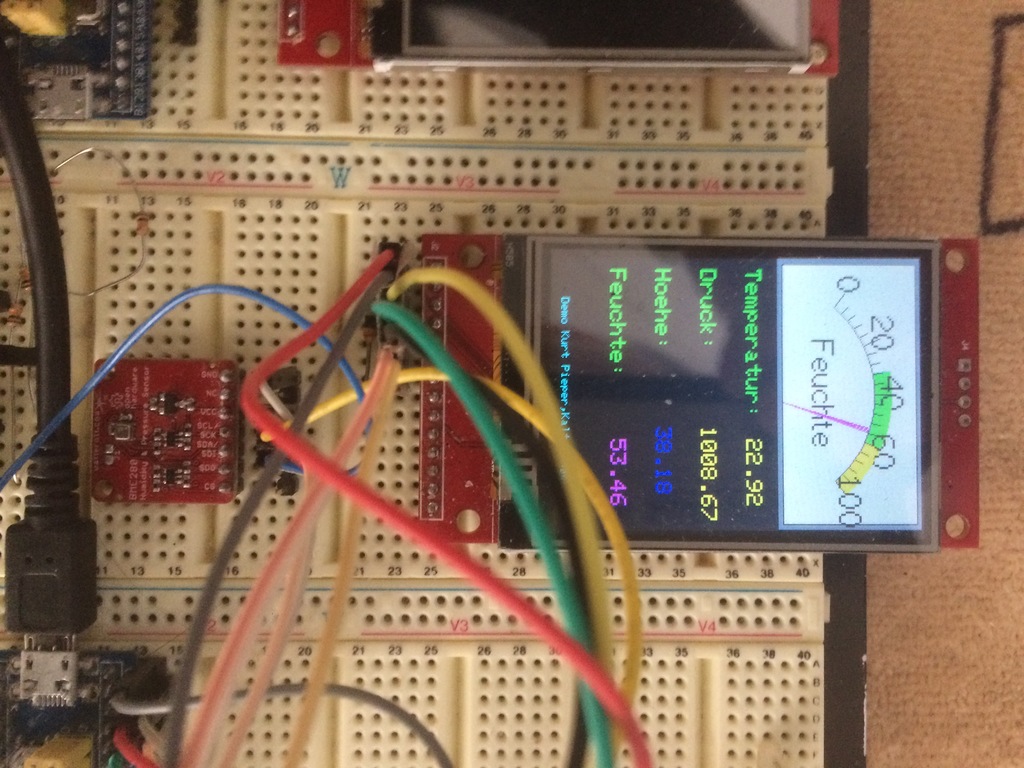
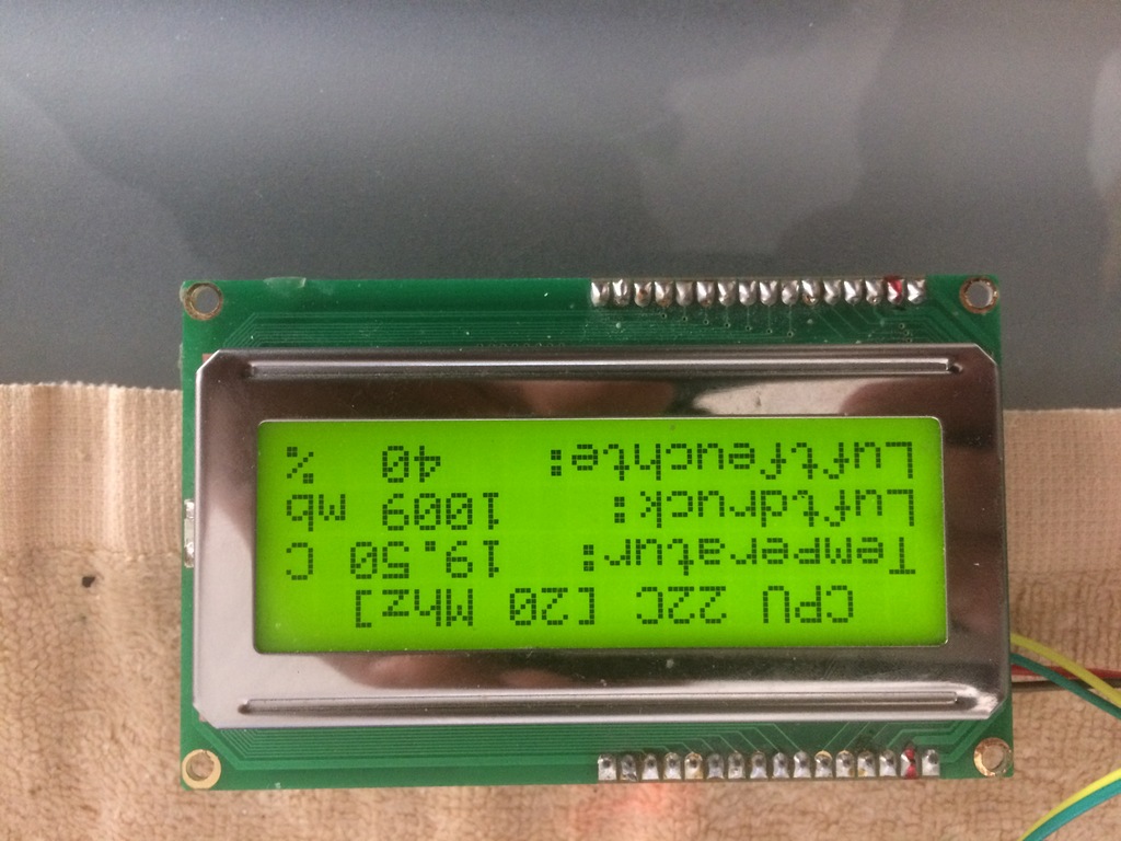
The four-line display would be enough for me!
Kurt
Here is a picture of my wild wiring with a BlueBill, bme 280 and TFT (China Import).
Kurt
Message has been deleted
Message has been deleted
Marco Maccaferri
Mar 31, 2021, 12:04:34 PM3/31/21
to retro...@googlegroups.com
Il 31/03/21 17:11, Kurt Pieper ha scritto:
> I'm not that great HiTech C programmer and I have problems converting
> an Arduino C program. The serial transmission can be omitted here.
> The display in the LCD would be my goal.
No, sorry I'm not familiar with that sensor, however you have everything
needed to make it work, after all it is a just a matter of seding the
commands and reading the results.
I suggest to get the datasheet of the sensor and look at it, along with
the Arduino code you posted, to know how to comunicate with it.
Best regards,
Marco
Message has been deleted

Greg Dyke
Apr 14, 2021, 2:45:10 PM4/14/21
to retro-comp
Hi Marco,
I must be doing something fundamentally silly on my SC126 but I'm at a loss.
I2CSCAN.AS compiles without complaint (and has the flag for the SC126 set).
When it runs, it just seems to return the whole range unmasked:
Any thoughts?
Greg
Marco Maccaferri
Apr 14, 2021, 3:06:43 PM4/14/21
to retro...@googlegroups.com
Il 14/04/21 20:45, Greg Dyke ha scritto:
> I must be doing something fundamentally silly on my SC126 but I'm at
> a loss.
>
> I2CSCAN.AS compiles without complaint (and has the flag for the SC126
> set).
>
> When it runs, it just seems to return the whole range unmasked:
It is possible that I missed something. Unfortunately I can't be of much
help, I don't have an SC126 so I haven't really tested it. As far as I
know the SCL and SDA bits seems correct, maybe there is somthing else I
haven't set correctly.
Best regards
Marco.
> I must be doing something fundamentally silly on my SC126 but I'm at
> a loss.
>
> I2CSCAN.AS compiles without complaint (and has the flag for the SC126
> set).
>
> When it runs, it just seems to return the whole range unmasked:
help, I don't have an SC126 so I haven't really tested it. As far as I
know the SCL and SDA bits seems correct, maybe there is somthing else I
haven't set correctly.
Best regards
Marco.

Chris Odorjan
Apr 14, 2021, 8:54:56 PM4/14/21
to retro-comp
On Wednesday, 14 April 2021 at 15:06:43 UTC-4 Marco Maccaferri wrote:
It is possible that I missed something. Unfortunately I can't be of much
help, I don't have an SC126 so I haven't really tested it. As far as I
know the SCL and SDA bits seems correct, maybe there is somthing else I
haven't set correctly.
There's a bit near the bottom of _i2c_write in I2CSCAN.AS:
COND SC126=0
ld d,a
3: in a,(_io)
bit _scl,a
jr z,3b
ld c,a
ld a,d
ENDC
ld d,a
3: in a,(_io)
bit _scl,a
jr z,3b
ld c,a
ld a,d
ENDC
It should probably be:
ld d,a
3: in a,(_io)
COND SC126=0
bit _scl,a
jr z,3b
ld a,d
3: in a,(_io)
COND SC126=0
bit _scl,a
jr z,3b
ENDC
ld c,a
ld a,d
I think the condition is to avoid clock stretching on SC126 but it ends up skipping the acknowledge bit entirely.
(I don't have an SC126 either, but I noticed this recently while using your code as a basis for testing a bit-banged I2C interface on a modified version of my DUART card. Thanks for the sample code, by the way!)
--
Chris Odorjan
Marco Maccaferri
Apr 15, 2021, 1:58:25 AM4/15/21
to retro...@googlegroups.com
Il 15/04/21 02:54, Chris Odorjan ha scritto:
> There's a bit near the bottom of _i2c_write in I2CSCAN.AS:
>
> COND SC126=0
> ld d,a
> 3: in a,(_io)
> bit _scl,a
> jr z,3b
> ld c,a
> ld a,d
> ENDC
>
> It should probably be:
>
> ld d,a
> 3: in a,(_io)
> COND SC126=0
> bit _scl,a
> jr z,3b
> ENDC
> ld c,a
> ld a,d
>
> I think the condition is to avoid clock stretching on SC126 but it
> ends up skipping the acknowledge bit entirely.
Ah, yes, that's it, good catch.
And I see that I2C.AS has it fixed, must have noticed the error but
forgot to fix I2CSCAN.AS.
Attached a new zip with the fix.
Thanks.
Best regards,
Marco
> There's a bit near the bottom of _i2c_write in I2CSCAN.AS:
>
> COND SC126=0
> ld d,a
> 3: in a,(_io)
> bit _scl,a
> jr z,3b
> ld c,a
> ld a,d
> ENDC
>
> It should probably be:
>
> ld d,a
> 3: in a,(_io)
> COND SC126=0
> bit _scl,a
> jr z,3b
> ENDC
> ld c,a
> ld a,d
>
> I think the condition is to avoid clock stretching on SC126 but it
> ends up skipping the acknowledge bit entirely.
And I see that I2C.AS has it fixed, must have noticed the error but
forgot to fix I2CSCAN.AS.
Attached a new zip with the fix.
Thanks.
Best regards,
Marco
Greg Dyke
Apr 15, 2021, 4:29:16 AM4/15/21
to retro-comp
Spot on, thank you both!
Greg
Reply all
Reply to author
Forward
Message has been deleted
0 new messages