SCMonitor for RIZ180
837 views
Skip to first unread message

Bill Shen
Aug 7, 2021, 5:15:58 PM8/7/21
to retro-comp
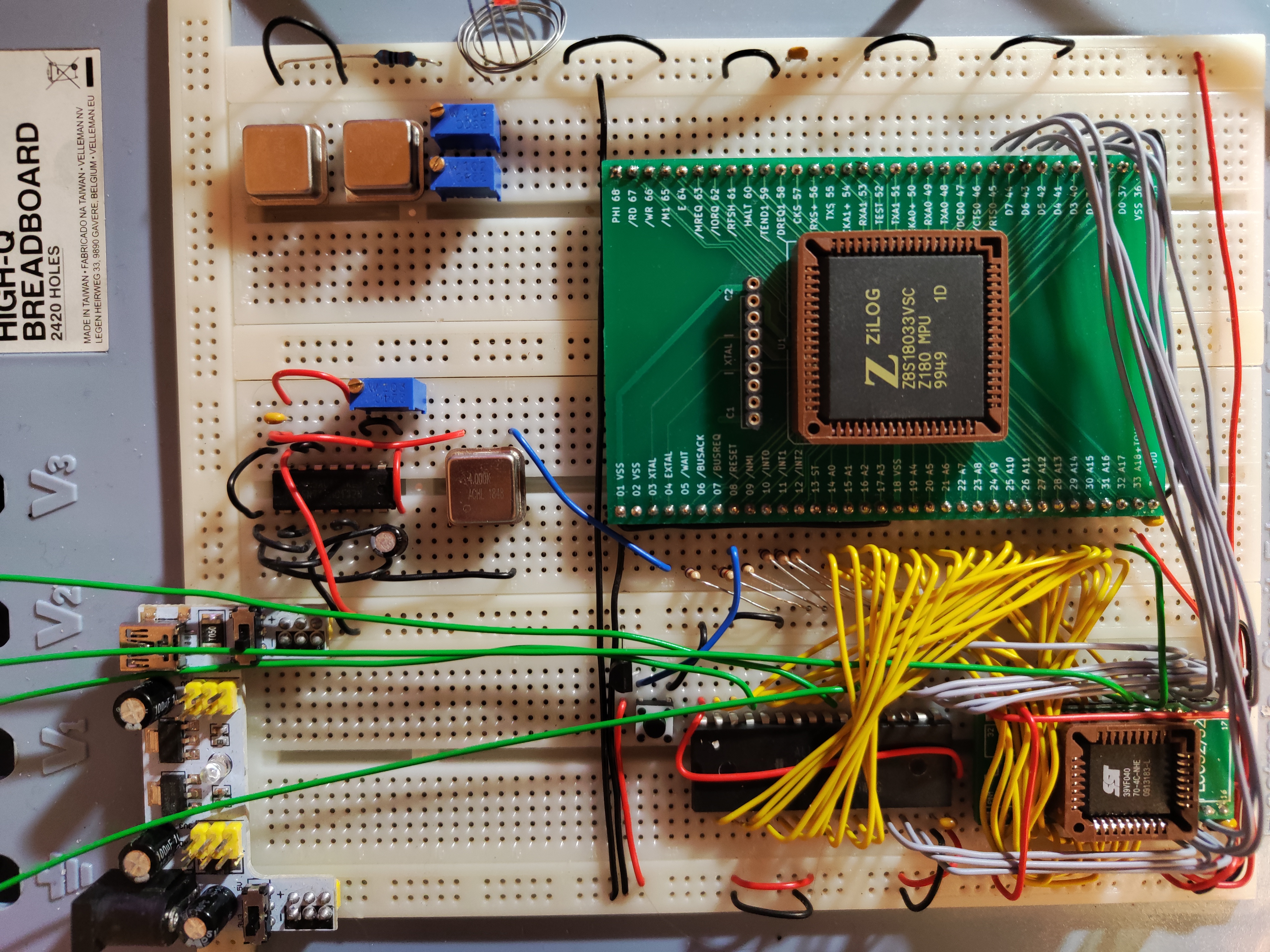
The original requester of RIZ180 like to have SCMonitor capability added to RIZ180. I hacked on SC126 version of SCMonitor and have it running on RIZ180. The hack is fairly simple: the 64-pin Z80180 only has 1/2meg memory space so RAM base is located at 0x40000 instead of 0x80000 for SC126. For the ROM version of SCMonitor, I patched the MMU initialization routine so common block 1 is assigned to 0x40000. For load-abel SCMonitor that is loaded and ran by RIZ180 monitor, I patched out the MMU initialization routine completely because RIZ180 monitor has already initialize the memory to RAM before load and run SCMonitor.
Patching SCMonitor is easy enough, but now I have a request: I like a version of SCMonitor that fits in 16K space. There are two reasons: 1), because 16K SCMonitor is copied into RAM and execute. It will have more space (48K) for BASIC; 2), for reason that's complicated (and tedious) to explain, SCMonitor + Startrek need to be lesser than 48K for it to be saved in CF disk by RIZ180 monitor. With a 32K SCMonitor, the total memory image exceeds 48K when Startrek program is loaded, so I'm unable to save the whole thing (SCMonitor+Startrek) into CF disk. If SCMonitor is 16K, I know from past experience that SCMonitor+Startrek can all be saved in CF. Then it can be recall & run instantly.
So my request is this: what dials and switches I need to twiddle to assemble a version of SCMonitor for 16K ROM? Thanks,
Bill
PS, the homepage for RIZ180 is here:
https://www.retrobrewcomputers.org/doku.php?id=builderpages:plasmo:riz180:riz180r1

Alan Cox
Aug 8, 2021, 10:47:59 AM8/8/21
to Bill Shen, retro-comp
PS, the homepage for RIZ180 is here:
https://www.retrobrewcomputers.org/doku.php?id=builderpages:plasmo:riz180:riz180r1
Nice and minimal.
Not sure the SPI port can be used for much though. You don't seem to have a chip select for it (I guess you'd steal the flow control for the other serial) ?
One of the DREQ lines could also do with being pulled down I think. The Z180 is weird in that you can't ignore DREQ in I/O<->memory DMA (eg CF adapter), and doubly weird that the CKA0 line magically turns into an input line during DMA even if you have it set to be muxed to CKA0 ! Either way they are inputs and shouldn't be unconnected ? DREQ1 in particular ought to be set up so that DMA runs flat out so you can DMA to/from the CF card.
Added to the rc2014-z180 emulator as "-m riz180"
Alan
Bill Shen
Aug 8, 2021, 6:59:45 PM8/8/21
to retro-comp
The Z80180 at 9.21MHz is fairly slow so it needs hardware handshake in order for the XMODEM transfer to work, so yes, I did use the serial port flow control pins for the console port. I have not tested SPI, so I have not discovered what kinda problem I'll have with SPI; it may not be useful as you said.
Thanks for the tip about DREQ. I do like to try DMA for CF disk accesses one of these days.
Bill
Thanks for the tip about DREQ. I do like to try DMA for CF disk accesses one of these days.
Bill

Steve Cousins
Aug 11, 2021, 4:51:07 PM8/11/21
to retro-comp
Hi Bill,
I'd use SCM v1.1 (not v1.2) as v1.2 uses a memory hungry framework to make it easier to support a greater range of hardware configurations. v1.1 still allows SCM + BASIC to fit in 16k, while v1.2 does not.
I think the only mods required to the SC126 configuration of SCM v1.1 are as follows:
File: \SCMonitor\Source\Config\SC_S6\Build.asm
Change
kROMTop: .SET 0x7F ;Top of banked ROM (hi byte only)
To
kROMTop: .SET 0x3F ;Top of banked ROM (hi byte only)
File: \SCMonitor\Source\Config\SC_S6\Rom_Info.asm
Change
.ORG 0x7FA0 ;File references downwards from 0x7FF0
To
.ORG 0x3FA0 ;File references downwards from 0x7FF0
I made these mods and the code assembled ok. A quick look at the output suggests all is as expected. But I didn't try burning a ROM.
Steve
Bill Shen
Aug 11, 2021, 9:39:14 PM8/11/21
to retro-comp
Steve,
Great! thanks for the help. I now have a SCMonitor + Startrek BASIC program that can be loaded from CF disk into RIZ180 memory and execute. This should make a nice demonstration for SCMonitor on RIZ180.
I did have to modify ROM_Info.asm with this line:
#INSERTHEX ..\Apps\MSBASIC_adapted_by_GSearle\SCMon_BASIC_code2000_data4000.hex
Otherwise the BASIC still have 32K RAM that starts from 0x8000.
Thanks again,
Bill

7alken
Oct 1, 2023, 3:47:16 AM10/1/23
to retro-comp
Hi Bill, I am almost ready with parts to wire riz180 on breadboard, as I have plcc68 Z8S180 here and also plcc flash (I have made own breadboard adapter for plcc Z180 as part of kicad learning and have socket adapter for the flash too), for sram I have here AS6C4008-55 so 512kB - please, will this be somehow useable in full for riz180? it seems at least 256kB maybe?, as A18 is switching in schematic both memory chips selects exclusivelly? BTW why is A18 fed to both CS and address line on the flash chip?? Will be larger RAM memory handled by rizmon too?
Also, I collected here 3V3 parts to build this - have 74LVC or and 138 decoder and 3.15V reset supervisor and of course oscillator. Tried to find if CFcard will run on 3V3 and it seems this is mandatory in spec, simply by providing only 3V3 Vcc for card does 3V3 logic? Hope it will run - the Z180 on breadboard is now at least counting on adress lines on 3V3...
Thanks,
Petr
Bill Shen
Oct 1, 2023, 8:27:07 AM10/1/23
to retro-comp
RIZ180 is building around older Z80180 which has a total addressable memory of 512K. Since you have Z8S180 which is faster and can address 1 meg memory and you already have 512K RAM, you may be interested in more capable design that can also support RomWBW. CF does work at 3.3V so does LVC logic, AS6C4008, and Z8S180. What flash are you using? There is a good chance it will also work at 3.3V at reduced performance. You likely have all the components to build a 3.3V Z180 RomWBW-capable system. Rizmon is a simple monitor so it can be easily adjusted to accommodate large memory space.
Do you have schematic of your design? I can comment on it and see how rizmon can be adjusted to work with it. I think I have a Z8S180 somewhere so I can duplicate your design and test out the modified rizmon.
Bill
Do you have schematic of your design? I can comment on it and see how rizmon can be adjusted to work with it. I think I have a Z8S180 somewhere so I can duplicate your design and test out the modified rizmon.
Bill
Bill Shen
Oct 1, 2023, 9:41:17 PM10/1/23
to retro-comp
Correction to my post above. Z80180 in DIP64 package does not have A19 bonded out so its addressable memory is limited to 512K. A19 is bonded out for the PLCC68 package.
Looking at the schematic of RIZ180, I found a shocking mistake; Z80180 is not powered! The power pin for Z80180 is pin 32, but a mistake in my library connected it to pin 2 which is XTAL input that should be floating. So Z80180 is powered through input protection diodes and XTAL apparently will function correctly if it is tied high. I've done good bit of testings early on and Z80180 appeared to work just fine in this configuration. Amazing!
The reason that I'm looking at the RIZ180 schematic is I believe connecting A19 of PLCC68 to flash chip select, replacing the 128K RAM with 512K RAM and hooking up A17 and A18 to 512K RAM will allow 512K flash and 512K RAM. Unfortunately the lost of 2nd RAM chip select for 512K RAM means I'll need to add another chip to decode the RAM chip select using nMREQ and A19.
I found a Z8S180 in my part bin so I'll prototype the changes and see if that works out.
Bill
7alken
Oct 2, 2023, 4:58:30 AM10/2/23
to retro-comp
Thank you Bill, I feel like I had very creative night )) ... collecting some cool ideas for my new enhanced system; just wire the SRAM and will be testing the base;
Petr
Bill Shen
Oct 2, 2023, 9:08:40 PM10/2/23
to retro-comp
Attached is the schematic for updated RIZ180 with 512K RAM and flash. U7 is added to decode chip select for RAM; DIP Z80180 is replaced with PLCC Z8S180; and 128K RAM is replaced with 512K RAM. I try to minimize the changes so I can prototype with existing pc board. I'll populate all components except DIP Z80180 and wire in the daughter board with PLCC Z8S180 and 74138.
Bill
Bill
7alken
Oct 2, 2023, 10:29:19 PM10/2/23
to Bill Shen, retro-comp
Many thanks Bill, here also some progress with wiring, but I need to make your updates )) ... and please, which is correct frequency of oscillator bound to current rizmon firmware? in schematic you still have 7.367 but on photos is 12.288 and in text is noted 18.432 )))
plus, one more question - if I would try to use PLD, can possibly this one 5V (7ns) ATF16V8C-7PU work at least slower on 3V3 too or its nonsense/unreliable? I thought as its CMOS it "may" be possible??
plus, one more question - if I would try to use PLD, can possibly this one 5V (7ns) ATF16V8C-7PU work at least slower on 3V3 too or its nonsense/unreliable? I thought as its CMOS it "may" be possible??
Petr
--
You received this message because you are subscribed to a topic in the Google Groups "retro-comp" group.
To unsubscribe from this topic, visit https://groups.google.com/d/topic/retro-comp/PONQAlHfCow/unsubscribe.
To unsubscribe from this group and all its topics, send an email to retro-comp+...@googlegroups.com.
To view this discussion on the web visit https://groups.google.com/d/msgid/retro-comp/75ede2d6-9ed6-4269-bb75-f376a351bba1n%40googlegroups.com.
7alken
Oct 2, 2023, 10:47:44 PM10/2/23
to Bill Shen, retro-comp
also, here are my adapters for PLCC68 and SDIP64 (and TQFP64 on top of it, as I seeked for some fast PIC32 things simply by this package and availability ...)
will post this soon to github also, but few of there can be probably sent to someone, if interested; I only forgot to put blocking caps directly on them, BUT now its generic for any kind of chip...
Petr
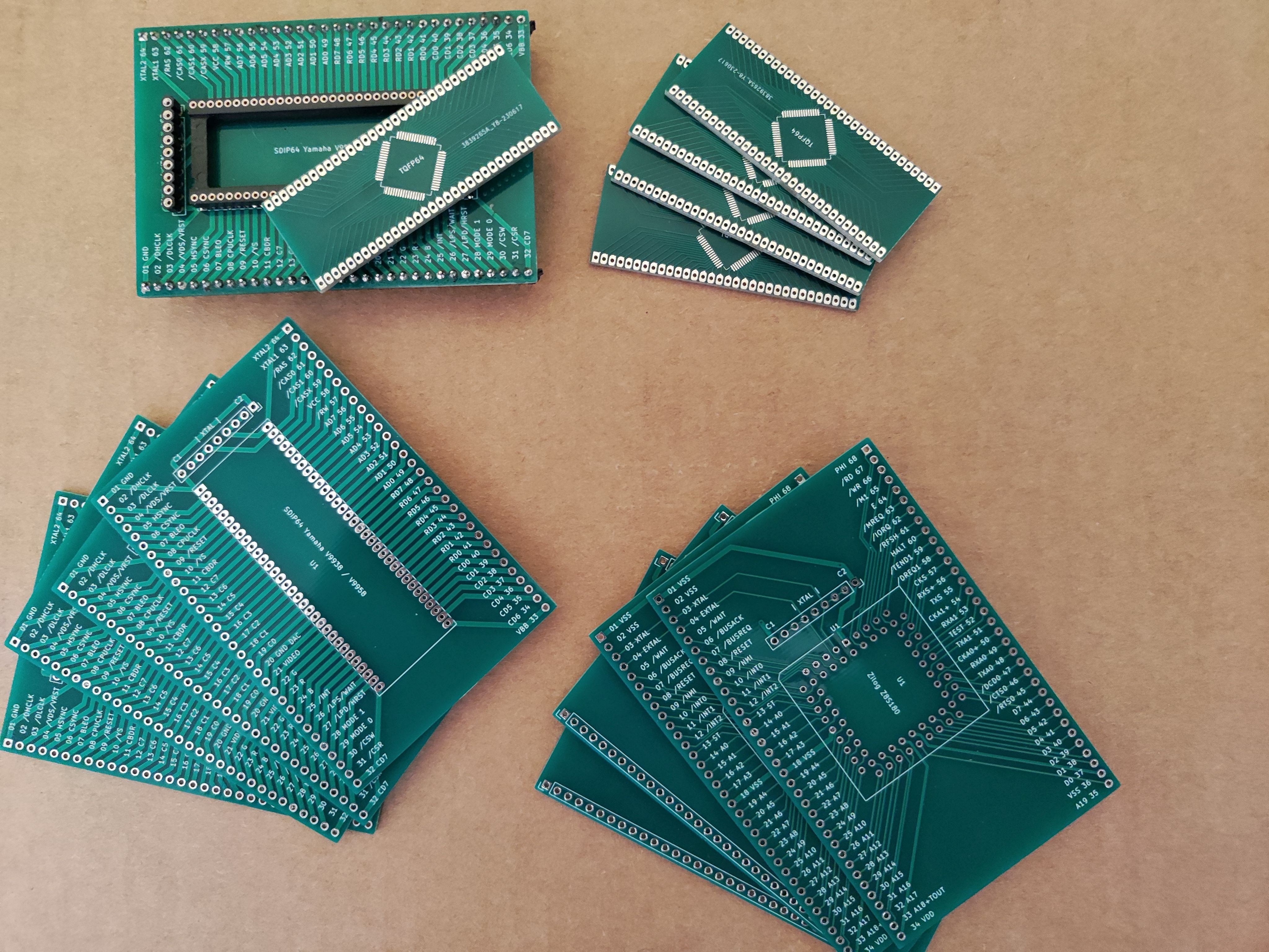
will post this soon to github also, but few of there can be probably sent to someone, if interested; I only forgot to put blocking caps directly on them, BUT now its generic for any kind of chip...
Petr
Bill Shen
Oct 2, 2023, 11:12:59 PM10/2/23
to retro-comp
You should use 18.432Mhz oscillator to get standard serial rate. Since you are using Z8S180, 36.864mhz also work, but it is probably too fast for breadboard.
I don’t have experience with AFT16V8 or ATF22V10. Earlier PLD like GAL22V10 are power hog so they are unlikely to run at 3.3V. ATF PLD may have the same issue. If you use CPLD, such as ATF1502, then it is available in 3.3V.
Bill
7alken
Oct 3, 2023, 5:40:42 AM10/3/23
to Bill Shen, retro-comp
thanks a lot thinking here if put 2/3 discretes or try immediately that PLD - I have here also 3V3
ATF22V10 so can program both and make experiment ...
.. its all about experiments :-)
.. its all about experiments :-)
To view this discussion on the web visit https://groups.google.com/d/msgid/retro-comp/1336338d-b65f-48b3-845b-7b3babbfcb02n%40googlegroups.com.
Bill Shen
Oct 3, 2023, 8:21:28 AM10/3/23
to retro-comp
With programmable logic, the design can simplify dramatically. With small CPLD like ATF1502, it can bootstrap from CF disk thus eliminating the flash and shrink design to just 512K RAM, Z180, CPLD, CF disk, and oscillator and RomWBW capable. It may even be possible to do that with 22V10 PLD instead of CPLD. That’ll require experimenting.
Bill
7alken
Oct 3, 2023, 10:49:29 AM10/3/23
to Bill Shen, retro-comp
thanks; ya, I have nothing against flash chip though; we used in 2063/Z80Retro! special RPI connected programmer using dual MCP23017 which requests Z80 for bus and then controls flash pins by MCP connected to I2C RPI on GPIO. This is useful and it also allows to do remote reset as I have always this 2063 system connected to programmer and RPI. For my new Z180 system I want to finally reuse this approach too, even reuse this existing programmer through adapter to the 2063 bus connector and/or design new one with maybe be SPI and providing on bus also some FAST (1,5Mb/4Mb) DUAL UART connected to RPI for in-system debugging against my virtual VMEX processor (which is not even specified yet, ya)))... Now as I think here what next, also getting some ideas how to use sync serial port (SPI) on Z180, as I in fact dont want to use SDCARD to this system if CFcard(faster) is provided. But that special "SPI" crazes me, IF I could not use it for BOTH SPI and I2C as special kind of host using some multiplexer chip (ya, those I2C special multiplexers as I researched on mouser are often just downstreaming I2C, but SOME, maybe, are only true fast analog multiplexers (or I dream about that), which may be as "dual" config used to multiplex even SPI to this one (master only) port - now reading adafruit doc abotu I2C as this is more complex protocol than raw SPI, but wondering if I could provide some host solution to this port to be used ALSO for I2C at the same time as for SPI and have it all multiplexed to the target slave devices .... if this crazy idea fail, obviously, then I am seeking for some simple I2C bridge chip to provide on board immediatelly few I2C and SPI ports too... in even ultra crazy scenario, I even dream about "remote I2C" for network like connections either by CAN tcvrs or rather RS485 ones, half-duplex differential 2-wire ... so I am quite "busy" now )))))
(well, found at least PCA9564, but wondering it it really couldnt be done in SW together with SPI over that sync serial port of Z180 ... and some multiplexer ...)
(well, found at least PCA9564, but wondering it it really couldnt be done in SW together with SPI over that sync serial port of Z180 ... and some multiplexer ...)
Do you pls know some I2C or I2C/SPI chip designed for easier interfacing to 8bit system? SPI is here okay, only CS encoder missing, but it something exists as single chip, it will solve it all too...
For the RIZ180 mod, I will first use the discretes and then experiment with replacing by PLD... ya, it WILL be finally there ...
Petr
To view this discussion on the web visit https://groups.google.com/d/msgid/retro-comp/f5d104c1-3a85-4f94-b1ae-1bb008c39734n%40googlegroups.com.
Bill Shen
Oct 3, 2023, 11:16:56 AM10/3/23
to retro-comp
Eliminating the flash solves one of the obstacle to people new to retro-computing—the need of purchasing a specialized flash programmer, a $70 item. Although PLD or CPLD also require programmer, but I use Altera USB Blaster clone that’s about $10. Design without flash is also simpler and cheaper to build; in addition, flash tends to be slow thus the speed bottleneck. You can run Z8S180 at 36.8Mhz no wait state with just RAM.
Most I2C devices are low data so I bit-bang I2C. OLED displays need more data, but with faster Z180, you should be able to achieve 20 frames/sec video rate on 64x128 pixels OLED display using bit-bang I2C.
Bill
7alken
Oct 3, 2023, 11:24:52 AM10/3/23
to retro-comp
ya, I agree with all ... for "2063" John made this thing and it was actually first board I built after many years :-)
https://github.com/Z80-Retro/2065-Z80-programmer
https://github.com/Z80-Retro/2065-Z80-programmer
7alken
Oct 3, 2023, 11:30:33 AM10/3/23
to retro-comp
in relation to CPLD, I started looking for ATF15xx but that programmer was quite barrier ... so also then probably thanks to you found MAX7000 trying to find 3V3 capable and available - have you any reliable sources of these CPLD still today?

Greg Holdren
Oct 3, 2023, 12:35:04 PM10/3/23
to retro-comp
Checkout this site for the ATF parts:
Greg
7alken
Oct 3, 2023, 4:34:08 PM10/3/23
to Greg Holdren, retro-comp
this is huge, many thanks Greg; till today, I thought about JTAG as some kind of magic; now with help of your link I found even this all: (searched how to bitbang JTAG)
https://www.khjk.org/log/2013/aug/jtagbang.html
https://eeandcs.blogspot.com/2015/08/jtagxsvf-library-for-arduino.html
https://www.eevblog.com/2013/07/27/eevblog-499-what-is-jtag-and-boundary-scan/
https://eeandcs.blogspot.com/2015/08/jtagxsvf-library-for-arduino.html
https://www.eevblog.com/2013/07/27/eevblog-499-what-is-jtag-and-boundary-scan/
again, thanks!
To view this discussion on the web visit https://groups.google.com/d/msgid/retro-comp/09762224-b815-4453-92ca-36e7da5489f5n%40googlegroups.com.
7alken
Oct 3, 2023, 4:41:20 PM10/3/23
to Greg Holdren, retro-comp
and, btw, its interesting that JTAG and even I2C are in fact pure retro protocols )) ... my dad repaired entire life cassette/tape recorders and at least in televisions, there was former philips/now nxp I2C chips; dont know if I2C was "defined" first/before SPI by former motorola/former freescale/now nxp as this is totally raw, sure )) ... in relation to IEEE hiding things, I wonder where is core of the all mess around - probably also in early nineties ... uff
Alan Cox
Oct 3, 2023, 4:53:31 PM10/3/23
to 7alken, Greg Holdren, retro-comp
i2c was 1982 although its early adoption was much narrower as Philips were quite keen on their patent licensing. SPI was I believe a year or two later, although unlike I2C SPI was never really properly defined, and there were lots of similar busses (The very similar 64180/Z180 CSIO was 1985 for example and I don't know if it was on other hitachi devices before that)
Alan
7alken
Oct 3, 2023, 5:09:08 PM10/3/23
to Alan Cox, Greg Holdren, retro-comp
thanks for this clarification Alan... I remember you somewhere told that Z180 CSIO port is somehow weird? with reversed bits order than todays regular SPI?

Warren Toomey
Oct 3, 2023, 5:30:48 PM10/3/23
to retro-comp
On Wednesday, 4 October 2023 at 02:35:04 UTC+10 Greg Holdren wrote:
Checkout this site for the ATF parts:
This is what I'm using to program my ATF1508s. The FT232H device cost me about USD$20 on Ebay. It takes about 12 seconds to send the SVF file to the CPLD with OpenOCD, and I can leave the CPLD in-circuit. Nice and easy!
Cheers, Warren

PauldB
Oct 3, 2023, 6:27:23 PM10/3/23
to retro-comp
On Tuesday, 3 October 2023 at 17:30:33 UTC+2 antos...@gmail.com wrote:
in relation to CPLD, I started looking for ATF15xx but that programmer was quite barrier ... so also then probably thanks to you found MAX7000 trying to find 3V3 capable and available - have you any reliable sources of these CPLD still today?
I recently bought some Altera EPM7032SLC44-10 and EPM7064SLC44-10 CPLDs from eBay seller 'funkward-tech'. The parts came in what looked like their original reel carrier-sleeves, then packed for shipping in what amounted to a 'cocoon' of white foam and plastic wrap.
I tested a couple of them using a simple test jig and Quartus and they passed the 'erased' test. That was a good sign. Then I programmed them (with an extra 'verify' check afterwards) and that also went fine. So they really seem to be new parts.
There have been a number of posts in the past asking for a reliable source of these Altera CPLDs. Perhaps I was just lucky, but the parts I got were of good quality with no signs of wear.
Note that I have NO connection whatsoever with this eBay seller, apart from buying these CPLDs. I'm only posting these links in the hope that they can help anyone looking for these easily-programmed and retro-friendly Altera CPLDs.
Links (note, the seller also lists larger quantities for some savings):
"Altera EPM7032SLC44-10 32 Marco Cell Complex EEPLD PLCC44 X 2PCS"
https://www.ebay.com/itm/152248369391
"Altera EPM7064SLC44-10 Complex Programmable Logic Device CPLD PLCC44 x 1PC NEW"
https://www.ebay.com/itm/164657861860
I saw that the seller also lists these larger CPLDs (I've not bought any of these yet):
"NOS EPM7128SLC84-15 CPLD MAX7000 128 Macrocells PLCC84 x 1pc"
https://www.ebay.com/itm/152572838520
If you're also looking for a USB-Blaster to program the CPLDs, I bought one last year from eBay seller 'lovesell2013' after finding a post dated April 2021 from Bill Shen with a link to it.
I just checked the seller's link again, and the listing is still active as "Mini Usb Blaster Cable For CPLD FPGA NIOS JTAG Programmer" for $4.52 plus $0.99 shipping.
Bill's post and the link to the item:
https://www.retrobrewcomputers.org/forum/index.php?t=rview&th=512&goto=8445#msg_8445
https://www.ebay.com/itm/altera-Mini-Usb-Blaster-Cable-For-CPLD-FPGA-NIOS-JTAG-Altera-Programmer/254626963665
HTH,
Paul
7alken
Oct 3, 2023, 7:13:08 PM10/3/23
to PauldB, retro-comp
thanks Warren and Paul, will investigate that all :-)
to return this SCMon/RIZ180 thread to the rails (for a while), here is interesting table for Z180 serial speed based on clock freq... sad it cant be separated - and its interesting that only multiples of 9.126 allow 57600bps to which I here settled because of CP/M xmodem limits without rts/cts
https://github.com/wwarthen/RomWBW/blob/master/Doc/Z180%20ASCI%20Baud%20Rate%20Options.pdf
--
You received this message because you are subscribed to a topic in the Google Groups "retro-comp" group.
To unsubscribe from this topic, visit https://groups.google.com/d/topic/retro-comp/PONQAlHfCow/unsubscribe.
To unsubscribe from this group and all its topics, send an email to retro-comp+...@googlegroups.com.
To view this discussion on the web visit https://groups.google.com/d/msgid/retro-comp/350a388b-d341-47a1-8e24-26bceb504fffn%40googlegroups.com.
7alken
Oct 3, 2023, 7:49:50 PM10/3/23
to PauldB, retro-comp
ya, this replies some of my CSIO questions ... so still seeking for some modern SPI/I2C interface for parallel bus to offload vintage cpu, so it may be also some MCU or FPGA ... just learning
https://groups.google.com/g/retro-comp/c/NyZGdcdr2Vk
https://groups.google.com/g/retro-comp/c/NyZGdcdr2Vk
7alken
Oct 3, 2023, 8:22:17 PM10/3/23
to PauldB, retro-comp
... starting to love <10ns SRAM without flash, yeah ))
https://stackoverflow.com/questions/3587826/is-there-a-built-in-function-to-reverse-bit-order
https://stackoverflow.com/questions/3587826/is-there-a-built-in-function-to-reverse-bit-order
7alken
Oct 3, 2023, 11:03:43 PM10/3/23
to PauldB, retro-comp
OT okay, it seems world madness started to accelerate also with MOSI/MISO redefinition as main/sub; will stand against this weird relation;
7alken
Oct 4, 2023, 6:51:47 AM10/4/23
to PauldB, retro-comp
As I2C was never designed for todays usage, is imho always good to consider multiplexer/expander chip to allow any combination of devices
(address field was intended to be unique in single television box only ... its impossible to address 2 identical sensors on single bus)
https://en.wikipedia.org/wiki/I%C2%B2C#####
https://en.wikipedia.org/wiki/I%C2%B2C#####
Alan Cox
Oct 4, 2023, 6:57:26 AM10/4/23
to 7alken, PauldB, retro-comp
On Wed, 4 Oct 2023 at 11:51, 7alken <antos...@gmail.com> wrote:
>
> As I2C was never designed for todays usage, is imho always good to consider multiplexer/expander chip to allow any combination of devices
> (address field was intended to be unique in single television box only ... its impossible to address 2 identical sensors on single bus)
> https://en.wikipedia.org/wiki/I%C2%B2C#####
Almost all sensors have strappable address selection. So it's very
>
> As I2C was never designed for todays usage, is imho always good to consider multiplexer/expander chip to allow any combination of devices
> (address field was intended to be unique in single television box only ... its impossible to address 2 identical sensors on single bus)
> https://en.wikipedia.org/wiki/I%C2%B2C#####
very rarely a problem.
Alan
7alken
Oct 4, 2023, 7:07:48 AM10/4/23
to PauldB, retro-comp
btw, nxp pi**ed me recently so much by throwing at me some acronym with already 12 or so characters, that I simply order everything from texas; howgh;
7alken
Oct 4, 2023, 7:21:32 AM10/4/23
to retro-comp
wow, thanks Alan for this note; it seems from me crude to "teach" here about something I have no experience with, ya ... although I have here lots of arduino/circuitpython devkits and even sensors, its all intended to be used by VMEX one day ... ya, I have head full of replacing arduino/circuitpython back again with assembler, unified finally; crude enough too, excuse me :-)
found this also, thanks
https://electronics.stackexchange.com/questions/306691/what-is-an-adressable-i2c-device-and-what-does-it-mean
https://www.ti.com/lit/an/scaa137/scaa137.pdf
and, my apologies;
found this also, thanks
https://electronics.stackexchange.com/questions/306691/what-is-an-adressable-i2c-device-and-what-does-it-mean
https://www.ti.com/lit/an/scaa137/scaa137.pdf
and, my apologies;
Petr
7alken
Oct 4, 2023, 10:03:53 AM10/4/23
to retro-comp
well, chip like
TMUX1204 looks cool, but its ugly tiny; so candidate for fabed DIP module of few? or if anybody can link similar analog multiplexers, I would be happy;
7alken
Oct 5, 2023, 8:30:39 PM10/5/23
to retro-comp
now, returning back to breadboard; I thought I have here only smd/soic 74lvc, but actually have in inventory 74ahc138/74ahc32 so will use that for 3V3;
in case something will be wrong, can try this brilliant initial testing code and tutorial to bring Z180 into life ...
http://www.vk1zdj.net/?p=525
in case something will be wrong, can try this brilliant initial testing code and tutorial to bring Z180 into life ...
http://www.vk1zdj.net/?p=525
7alken
Oct 9, 2023, 9:36:27 PM10/9/23
to retro-comp
Hi Bill, kindly please, I have the RIZ180 on breadboard and RIZMON directly didnt worked, so now I have tested blinking on RTS0 from falsh code, but when I added config of ASCI0 to 9600bps at 18.432 it does still nothing, it blinks, but doesnot sent over BT-Serial module I had connected... what can be please wrong here: ??
ORG 0
DI ; disable interrupts
LD A, 0C0h ; relocate I/O register to 0xC0
OUT0 (ICR), A
LD A,64H ; transmit, receive enable, 8-bit 1 stop
OUT0 (CNTLA0),A
LD A,32+02
OUT0 (CNTLB0),A ; divided by 1920, 9600 with 18.432MHz clock
;LD A,0
;OUT0 (CNTLE0),A ;
LOOP:
LD BC, 0010h ;Loads BC with hex 0010
Outer0: LD DE, 1000h ;Loads DE with hex 1000
Inner0: DEC DE ;Decrements DE
LD A, D ;Copies D into A
OR E ;Bitwise OR of E with A (now, A = D | E)
JP NZ, Inner0 ;Jumps back to Inner0 label if A is not zero
DEC BC ;Decrements BC
LD A, B ;Copies B into A
OR C ;Bitwise OR of C with A (now, A = B | C)
JP NZ, Outer0 ;Jumps back to Outer0 label if A is not zero
; LD A, 0
; OUT (RxStat), A
LD A, 65 ;SEND "A"
OUT (TxData), A
LD A, 64H ;Turn ON Status LED (/RTS0)
OUT0 (CNTLA0),A
LD BC, 0010h ;Loads BC with hex 0010
Outer: LD DE, 1000h ;Loads DE with hex 1000
Inner: DEC DE ;Decrements DE
LD A, D ;Copies D into A
OR E ;Bitwise OR of E with A (now, A = D | E)
JP NZ, Inner ;Jumps back to Inner label if A is not zero
DEC BC ;Decrements BC
LD A, B ;Copies B into A
OR C ;Bitwise OR of C with A (now, A = B | C)
JP NZ, Outer ;Jumps back to Outer: label if A is not zero
; LD A, 0
; OUT (RxStat), A
LD A, 66 ;SEND "B"
OUT (TxData), A
LD A, 74H ;Turn OFF Status LED (/RTS0)
OUT0 (CNTLA0),A
JP LOOP
7alken
Oct 10, 2023, 4:49:25 AM10/10/23
to retro-comp
ufff, we are sending ... I tried to modify init better for Z8S180 according to user manual and changed order of storing to RTS0 LED change before TDR0 data write ...
LD A,64H ; transmit, receive enable, 8-bit 1 stop
OUT0 (CNTLA0),A
OUT0 (CNTLB0),A ; divided by 1920, 9600 with 18.432MHz clock
LOOP:
LD BC, 0010h ;Loads BC with hex 0010
Outer0: LD DE, 1000h ;Loads DE with hex 1000
Inner0: DEC DE ;Decrements DE
LD A, D ;Copies D into A
OR E ;Bitwise OR of E with A (now, A = D | E)
JP NZ, Inner0 ;Jumps back to Inner0 label if A is not zero
DEC BC ;Decrements BC
LD A, B ;Copies B into A
OR C ;Bitwise OR of C with A (now, A = B | C)
JP NZ, Outer0 ;Jumps back to Outer0 label if A is not zero
LD BC, 0010h ;Loads BC with hex 0010
Outer: LD DE, 1000h ;Loads DE with hex 1000
Inner: DEC DE ;Decrements DE
LD A, D ;Copies D into A
OR E ;Bitwise OR of E with A (now, A = D | E)
JP NZ, Inner ;Jumps back to Inner label if A is not zero
DEC BC ;Decrements BC
LD A, B ;Copies B into A
OR C ;Bitwise OR of C with A (now, A = B | C)
JP NZ, Outer ;Jumps back to Outer: label if A is not zero
plus there was single OUIT instead of OUT0 ...
ORG 0
DI ; disable interrupts
DI ; disable interrupts
LD A, ROFF ; relocate I/O register to 0xC0
OUT0 (ICR), A
LD A, 00h ; Clock Multiplier OFF
OUT0 (CMR), A
LD A, 80h ; Clock Divider OFF
OUT0 (CCR), A
OUT0 (ICR), A
LD A, 00h ; Clock Multiplier OFF
OUT0 (CMR), A
LD A, 80h ; Clock Divider OFF
OUT0 (CCR), A
LD A,64H ; transmit, receive enable, 8-bit 1 stop
OUT0 (CNTLA0),A
LD A,22H
OUT0 (CNTLB0),A ; divided by 1920, 9600 with 18.432MHz clock
LD A,60H
OUT0 (ASEXT0),A ;
OUT0 (ASEXT0),A ;
LOOP:
LD BC, 0010h ;Loads BC with hex 0010
Outer0: LD DE, 1000h ;Loads DE with hex 1000
Inner0: DEC DE ;Decrements DE
LD A, D ;Copies D into A
OR E ;Bitwise OR of E with A (now, A = D | E)
JP NZ, Inner0 ;Jumps back to Inner0 label if A is not zero
DEC BC ;Decrements BC
LD A, B ;Copies B into A
OR C ;Bitwise OR of C with A (now, A = B | C)
JP NZ, Outer0 ;Jumps back to Outer0 label if A is not zero
LD A, 64H ;Turn ON Status LED (/RTS0)
OUT0 (CNTLA0),A
OUT0 (CNTLA0),A
LD A, 65 ;SEND "A"
OUT0 (TxData), A
OUT0 (TxData), A
LD BC, 0010h ;Loads BC with hex 0010
Outer: LD DE, 1000h ;Loads DE with hex 1000
Inner: DEC DE ;Decrements DE
LD A, D ;Copies D into A
OR E ;Bitwise OR of E with A (now, A = D | E)
JP NZ, Inner ;Jumps back to Inner label if A is not zero
DEC BC ;Decrements BC
LD A, B ;Copies B into A
OR C ;Bitwise OR of C with A (now, A = B | C)
JP NZ, Outer ;Jumps back to Outer: label if A is not zero
LD A, 74H ;Turn OFF Status LED (/RTS0)
OUT0 (CNTLA0),A
OUT0 (CNTLA0),A
LD A, 66 ;SEND "B"
OUT0 (TxData), A
JP LOOP
JP LOOP
7alken
Oct 10, 2023, 5:06:55 AM10/10/23
to retro-comp
well, now I dont know if this part of RIZMON is correct with modified memory from 128k to 512k SRAM ... dont understand MMU, yet ...
ORG 100h
;LD A, ROFF ; relocate I/O register to 0xC0
;OUT0 (ICR), B
LD A, 4Fh ; map RAM physical base, so page $5b mapped to logical 0xc000
OUT0 (CBR), A ; write to common base reg
LD A, 0C0h ; common area is 0xc000-0xffff
OUT0 (CBAR), A ; set common/bank register
LD HL, 0B000h ; source
LD DE, 0C000h ; destination
LD BC, 1000h ; copy 4K from EPROM into RAM
LDIR
LD A, 50h ; by changing mapping of RAM physical base, I move copied program to 0xb000
OUT0 (CBR), A ;
LD A, 80h ; common area is 0x8000-8FFF
OUT0 (CBAR), A
JP 0B400h
7alken
Oct 10, 2023, 7:14:53 AM10/10/23
to retro-comp
ya, will be following this MMU tutorial linked by beauty diagnostic page of VK1ZDJ ... as I want to understand well the Z8S180:
http://oneweekwonder.blogspot.com/2017/12/z180-mmu-tiny.html
http://oneweekwonder.blogspot.com/2017/12/z180-mmu-tiny.html
Bill Shen
Oct 10, 2023, 9:21:58 AM10/10/23
to retro-comp
Good, you are making rapid progress. I can't keep up with you. You've already figured out the difference between OUT (TxData),A <-- won't work and OUT0 (TxData),A when addressing Z180 internal resources.
MMU routine will change to accommodate the memory change from 128K to 512K RAM. I'll need to read up Z8S180 MMU to refresh my memory. It was somewhat strange, as I recall.
Bill
MMU routine will change to accommodate the memory change from 128K to 512K RAM. I'll need to read up Z8S180 MMU to refresh my memory. It was somewhat strange, as I recall.
Bill
7alken
Oct 10, 2023, 11:08:40 AM10/10/23
to retro-comp
Umm, you are far more experienced, I am only focusing now... but this is yours COUT from RIZMON and here is OUT not OUT0 ... it means that "original" Z180 and Z8S180 behave differently and have even different MMU??
COUT:
;output char in regA
PUSH AF
CHKEMPTY:
IN A, (RXSTAT) ;read status
AND 2
JR Z, CHKEMPTY
POP AF
OUT (TXDATA), A
RET
;output char in regA
PUSH AF
CHKEMPTY:
IN A, (RXSTAT) ;read status
AND 2
JR Z, CHKEMPTY
POP AF
OUT (TXDATA), A
RET
Bill Shen
Oct 10, 2023, 11:28:04 AM10/10/23
to retro-comp
Hmmm, interesting... I looked at Rizmon as published in my RIZ180 homepage and this is the COUT routine:
cout:
;output char in regA
push af
chkEmpty:
in0 a,(RxStat) ;read status
and 2
jr z,chkEmpty
pop af
out0 (TxData),a
ret
;output char in regA
push af
chkEmpty:
in0 a,(RxStat) ;read status
and 2
jr z,chkEmpty
pop af
out0 (TxData),a
ret
So, where did your COUT routine come from?
Not all flavors of Z180 are the same, they do have different peripherals, but the core functions like MMU and methods of accessing internal peripherals are the same.
Bill
7alken
Oct 10, 2023, 4:11:14 PM10/10/23
to retro-comp
aaarrgghh, big excuse me Bill, ... that GPT4 beast, I only asked to reformat code WITHOUT CHANGES into columns and uppercased (then I added some more symbols manually etc), as I am using here your rizmon and "2063" retromon for months for testing of ASMX/ZMAC/UZ80AS using this script - just for better readability for me here, learning Z80 asm also in fact....
BIG lesson learned ... thank YOU :-(
SET OUT=out
SET PRG=rizmon
SET SRC=mixworx-rizmon.asm
md %OUT%
md %OUT%\zmac
md %OUT%\zmac\%PRG%
md %OUT%\uz80as
md %OUT%\uz80as\%PRG%
md %OUT%\asmx
md %OUT%\asmx\%PRG%
zmac %SRC% --z180 --od %OUT%\zmac\%PRG% 2> %OUT%\zmac\%PRG%\%PRG%.err
uz80as --target=hd64180 %SRC% %OUT%\uz80as\%PRG%\%PRG%.bin %OUT%\uz80as\%PRG%\%PRG%.lst %OUT%\uz80as\%PRG%\%PRG%.exp 2> %OUT%\uz80as\%PRG%\%PRG%.err
asmx -C Z180 -e -w -o %OUT%\asmx\%PRG%\%PRG%.hex -l %OUT%\asmx\%PRG%\%PRG%.lst -- %SRC% 2> %OUT%\asmx\%PRG%\%PRG%.err
asmx -C Z180 -e -w -b -o %OUT%\asmx\%PRG%\%PRG%.bin -l %OUT%\asmx\%PRG%\%PRG%.lst -- %SRC% 2> %OUT%\asmx\%PRG%\%PRG%.err
pause
7alken
Oct 12, 2023, 3:02:21 AM10/12/23
to retro-comp
kindly please, this drives me crazy, I am unable to block copy 4kB ROM to RAM, when I copy single byte, its okay ... (first ASCI0 sent is "R")
OUT0 (CBR), A ; write to common base reg
OUT0 (CBAR), A ; set common/bank register
LD BC, 1000h ; copy 4K from EPROM into RAM
I tried it at 18MHz, then slowed down to 9MHz, usually using LDIR first, then rewrite it as routine, ... NO, I am LOST ... totally.... :-(
ORG 0
DI ; disable interrupts
LD A, ROFF ; relocate I/O register to 0xC0
OUT0 (ICR), A
LD A, 00h ; Clock Multiplier OFF
OUT0 (CMR), A
;LD A, 80h ; Clock Divider OFF
DI ; disable interrupts
LD A, ROFF ; relocate I/O register to 0xC0
OUT0 (ICR), A
LD A, 00h ; Clock Multiplier OFF
OUT0 (CMR), A
;LD A, 80h ; Clock Divider OFF
LD A, 00h ; Clock Divider 2
OUT0 (CCR), A
LD A, 64H ; transmit, receive enable, 8-bit 1 stop
OUT0 (CNTLA0),A
;LD A, 22H ; divided by 1920, 9600 with 18.432MHz clock
LD A, 21H ; divided by 960, 9600 with 9.216MHz clock (CCR divider 2)
OUT0 (CNTLB0),A
LD A, 60H
OUT0 (ASEXT0),A ;
LD A, 8Bh ; map RAM physical base, so page $8B mapped to logical 0xc000
OUT0 (CBR), A ; write to common base reg
LD A, 00h ; map ROM physical base, so page $00 mapped to logical 0x0000
OUT0 (BBR), A ; write to common base reg
LD A, 0C0h ; common area is 0xc000-0xffff (RAM $8B)
OUT0 (BBR), A ; write to common base reg
LD A, 0C0h ; common area is 0xc000-0xffff (RAM $8B)
OUT0 (CBAR), A ; set common/bank register
LD HL, 0B000h ; ROM source
LD DE, 0C000h ; RAM destination
LD DE, 0C000h ; RAM destination
LD BC, 1000h ; copy 4K from EPROM into RAM
;THIS DOES NOT WORK!!! - "R" expected at 0C002h !!!!!!!!!!!!!
;LDIR
COPY: LD A,(HL)
LD (DE),A
INC HL
INC DE
DEC BC
LD A,B
OR C
JP NZ, COPY
;LD A, 50h ; by changing mapping of RAM physical base, I move copied program to 0xb000
;LD A, 80h ; by changing mapping of RAM physical base, I move copied program to 0xb000
;OUT0 (CBR), A ;
; LD A, 80h ; by changing mapping of RAM physical base, I move copied program to 0xb000
; OUT0 (CBR), A ;
; LD A, 00h ; map RAM physical base, so page $00 mapped to logical 0x0000
; OUT0 (BBR), A ; write to common base reg
; LD A, 00H ; all memory are now RAM
; OUT0 (CBAR),A
;THIS WORKS, COPIES ONLY 0B002h to 0C002h
;BY COMMENTING THIS OUT, THE BLOCK LDIR/ROUTINE DOEST COPY 0B002h to 0C002h ???????
LD HL, 0B002h ; ROM source
LD DE, 0C002h ; RAM destination
LD A,(HL)
LD (DE),A
;EXPECTING "R" HERE BY COPY
LD HL, 0C002h ; "R"
;LD (HL), 67
LD A, (HL)
OUT0 (TxData), A
;STOP: JP STOP
;JP 100h
7alken
Oct 12, 2023, 7:31:26 AM10/12/23
to retro-comp
of course this snippet works in simulator inside RAM ... I only cant understand why it copies something different in previous example, with properly setup common area into RAM, and when single byte IS copied okay - the block simply isnt, there is something different at C002, while it must be copy of B002 ... crazy, I cant see anything wrong :-(
LD HL, 0B000h ; ROM source
LD DE, 0C000h ; RAM destination
LD BC, 1000h ; copy 4K from EPROM into RAM
;THIS DOES NOT WORK!!! - "R" expected at 0C002h !!!!!!!!!!!!!
;LDIR
COPY: LD A,(HL)
LD (DE),A
INC HL
INC DE
DEC BC
LD A,B
OR C
JP NZ, COPY
LD HL, 0B000h ; ROM source
LD DE, 0C000h ; RAM destination
LD BC, 1000h ; copy 4K from EPROM into RAM
;THIS DOES NOT WORK!!! - "R" expected at 0C002h !!!!!!!!!!!!!
;LDIR
COPY: LD A,(HL)
LD (DE),A
INC HL
INC DE
DEC BC
LD A,B
OR C
JP NZ, COPY
7alken
Oct 12, 2023, 8:15:33 AM10/12/23
to retro-comp
ufff, I see it now ... by lowering the BC to 3 it works, and tested it works until 82, ... and I have miswired RAM A4..A7 to VSS,A4,A5,A6 ... A7 is NOT connected ...
so, mea culpa again ))
7alken
Oct 12, 2023, 8:54:22 AM10/12/23
to retro-comp
uff, okay, I am now in RIZMON by this MMU code:
ORG 100h
LD A, 8Ah ; map RAM physical base, so page $8A mapped to logical 0xc000
OUT0 (CBR), A ; write to common base reg
LD A, 00h ; map ROM physical base, so page $00 mapped to logical 0x0000
OUT0 (BBR), A ; write to bank base reg
LD A, 0C0h ; common area is 0xc000-0xffff
OUT0 (CBAR), A ; set common/bank register
LD HL, 0B000h ; source
LD DE, 0C000h ; destination
LD BC, 1000h ; copy 4K from EPROM into RAM
LDIR
LD A, 8Bh ; by changing mapping of RAM physical base, I move copied program to 0xb000
OUT0 (CBR), A ;
LD A, 80h ; common area is 0x8000-8FFF
OUT0 (CBAR), A
JP 0B400h
ORG 100h
LD A, 8Ah ; map RAM physical base, so page $8A mapped to logical 0xc000
OUT0 (CBR), A ; write to common base reg
LD A, 00h ; map ROM physical base, so page $00 mapped to logical 0x0000
LD A, 0C0h ; common area is 0xc000-0xffff
OUT0 (CBAR), A ; set common/bank register
LD HL, 0B000h ; source
LD DE, 0C000h ; destination
LD BC, 1000h ; copy 4K from EPROM into RAM
LDIR
OUT0 (CBR), A ;
LD A, 80h ; common area is 0x8000-8FFF
OUT0 (CBAR), A
JP 0B400h
Bill Shen
Oct 12, 2023, 9:19:29 AM10/12/23
to retro-comp
Excellent. I see you've modified the MMU so RAM is at high 512K and ROM at low 512K.
Bill Shen
Oct 12, 2023, 8:51:47 PM10/12/23
to retro-comp
Oh, very nice! Is Z8S180 CPU clock at 36.8MHz or 18.4MHz (1/2 of 36.8MHz)?
7alken
Oct 12, 2023, 9:17:48 PM10/12/23
to Bill Shen, retro-comp
I have 18.432 XTAL and set CMR multiplier;
btw tested also stock RomWBW SC126 and SC131 with BT-Serial at 115200 + mode com0 57600 and xm, xmodem to ramdisk A:
(dont know yet how to rebuild RomWBW for 57600 default)
I dont have here the chips for SC126/131, so will probably try to squeeze entire logic to ATF22LV10-30, at least for SDCARD interface of SC131
To view this discussion on the web visit https://groups.google.com/d/msgid/retro-comp/76e4d297-cbd7-4bb2-9a37-5583f50791b4n%40googlegroups.com.
7alken
Oct 13, 2023, 12:16:37 AM10/13/23
to Bill Shen, retro-comp
weird, I tried for several hours to repeat that 36.8MHz at 3V3 but without success, at 5V it seemed working but then stopped too, I dont know if it was totally cold or so, dont know ... tried to post here rizmod mods ... so now at least my reformatted version with 18.432 at 3V3 ensured (115200baud)
(after signon are listed CMR/CCR/CNTLB0 port values)
(after signon are listed CMR/CCR/CNTLB0 port values)
Bill Shen
Oct 13, 2023, 8:48:04 AM10/13/23
to retro-comp
You are making great progress. Intermittent problem is hard to diagnose, especially without real hardware, so I'm going ahead and building up the pc board + PLCC prototype shown on Oct 2 post.
7alken
Oct 13, 2023, 11:13:32 AM10/13/23
to Bill Shen, retro-comp
yes, may be it worked at 36MHz when I had BT-Serial adapter (sure radiates at 2.4GHz and it may interference something) placed near CPU and vertically, but I dont know, can try it again, I am almost sure it was working, huh... okay, nevermind, now I rebuilt latest RomWBW to 57600 default, as this is really max for XMODEM and reconfiguring BT JDY-33 here using my ugly arduino sketch is unreliable/slow and real pita ... so I have them all named separately and want all forced to 57600 for ANY sw I adapt...
Now, SC131 SD with soldered microsd/sd socket as native 3V3 is probably easiest storage, but for rizmon support, I will probably try to wire CF adapter with decomposed flat cable (originally intended part for Amiga)
As I reviewed RomWBW configs, I am trying to match whats supported there, but I also plan in some near future to try that NXP I2C/SPI bridges directly wired to CSIO (I2C one is direct Mode3 with bits reversal), which would be something new ... this is far plan; more near seems to be using the molex 2mm/2mm 2x15=30pin connectors sets for 3V3 bus, which I will probably discuss here how to do it well (no big plans with it, only for my local things here, not sure abotu all requirements, trying to fetch info from RCBus creation discussion), for sure there will be option for single connector "RC26"-like cards, and some 60pin subset of RCBus, so I will go to KiCad soon too
To view this discussion on the web visit https://groups.google.com/d/msgid/retro-comp/da1240ad-3eea-436f-9a26-9feb459e9586n%40googlegroups.com.
Bill Shen
Oct 13, 2023, 12:37:59 PM10/13/23
to retro-comp
OK, I made the hardware modifications and a few mods to the RIZmon and able to boot it up. This is 5V system with the voltage supervisor is set to 4.5V. CF interface is working. I'll crank up the clock and looking into porting RomWBW to it. It may be possible to have both CF disk and SD disk, that may be interesting...
Bill Shen
Oct 13, 2023, 2:35:35 PM10/13/23
to retro-comp
Here is a simpler RIZ180W (W is for version with 512K RAM&ROM). The 74138 of CF decode is replaced with 74139 so CF addresses are not a full decode resulting in duplicated I/O addresses at 0x90-0x9F. This duplicated I/O existed in earlier versions of CF board. In fact, some software still requires CF at both 0x10 and 0x90. This simpler design saves one chip.
I should mention there are already many other outstanding RomWBW-capable Z180 designs that are more popular and better supported. Only thing different about RIZ180W is having the CF interface on the motherboard, but conventional wisdom indicated the SD disk is cheaper, more available and not significantly slower than CF disk.
Bill
On Friday, October 13, 2023 at 9:13:32 AM UTC-6 antos...@gmail.com wrote:
7alken
Oct 13, 2023, 3:08:24 PM10/13/23
to retro-comp
thanks Bill for update, I loved RIZ180 simplicity immediately ... :-)
Message has been deleted
7alken
Oct 15, 2023, 11:51:54 AM10/15/23
to retro-comp
hi Bill, I understand you want to maintain minimal chips count on RIZ180(W) ... but I here tried the in-system flashing on breadboard, I added this to RomWBW updater.asm a flash.com:
but then I spent several hours by combination of my own mistakes introduced in assembly and forgotten fixed Vcc on flash chip /WE ...
updater.asm:
.DW $BFD7 ; 39SVF040 8
flash4.c:
{ 0xBFD7, "39SVF040", 32, 128, ST_NORMAL },
.DW $BFD7 ; 39SVF040 8
flash4.c:
{ 0xBFD7, "39SVF040", 32, 128, ST_NORMAL },
but then I spent several hours by combination of my own mistakes introduced in assembly and forgotten fixed Vcc on flash chip /WE ...
after introducing one 74AHC32 OR gate for /MREQ+/WE the flash.com started to detect, but the xmodem updater.asm was still wild, but
this was only because of my debug PRTSTR0 of ChipID detected which corrupted BC (!!!), so I was absolutely unable to read ChipID,
really for several hours ... when I finally found that PRTSTR0 is culprit corrupting my registers in the middle ... sheesh;
(this BIG lesson RElearned lead me also to my HUGE BOLD note to support firm stack handling pseudo instructions for my VMEX,
as RISC-V generally has NO specific opcodes for PUSH/POP - its intended for code generation, but I want to support hand-made 32bit assembly,
as simple as possible, and this simple/firm stack support is absolutely crucial ... you know, returning to ASM/stack/regs after 40 years ))))
(so my, "RIZ180W-inspired" system will really have that 22LV10 PLD at least... as chips count starts to grow;)
Petr
7alken
Oct 15, 2023, 11:56:40 AM10/15/23
to retro-comp
I also contacted Will to update the flash4, he will probably add entire 3V3 family;
(thing found in flash4 is that during ChipID, there is 10ms delay for "some" chips, this is missing in RomWBW updater.asm)
(thing found in flash4 is that during ChipID, there is 10ms delay for "some" chips, this is missing in RomWBW updater.asm)
Bill Shen
Oct 15, 2023, 2:44:40 PM10/15/23
to retro-comp
In the case of RIZ180W where RAM and flash chip selects are decoded with 74139 that's qualified by /MREQ, it is not necessary to further qualify flash's write enable, so the chip count should stays the same. For your breadboard, instead of adding another OR gate, you can rewire the existing OR that drives the output enable of flash as follow:
* A19 connects to pin 12 of 7432 (originally /RD was connected to pin 12),
* pin 11 of 7432 connects to chip enable of flash (originally A19 was connected to chip enable of flash),
* /RD connects to flash's output enable,
* /WR connects to flash's write enable.
The idea is to qualify flash's chip enable with A19 and /MREQ so it won't see a spurious access.
Bill
7alken
Oct 16, 2023, 8:20:13 AM10/16/23
to Bill Shen, retro-comp
Thank you Bill for this info, I havent connected the CF card yet, so it was quick fix now...
Based on your experience, I ordered cheap altera usb blaster clone and some epm3064 44pin tqfp/plcc for experiments too :-)
To view this discussion on the web visit https://groups.google.com/d/msgid/retro-comp/0d46599b-255f-4646-b1cc-58b6d402f1e0n%40googlegroups.com.
Bill Shen
Oct 16, 2023, 8:39:56 AM10/16/23
to retro-comp
Ah, I've forgotten about EPM3xxx family which is 3.3V CPLD. In fact I think I've quite a stash of EPM3128 somewhere.
7alken
Oct 16, 2023, 9:33:06 AM10/16/23
to Bill Shen, retro-comp
yeah, found today this great japanese page about CPLD overviews, comparisons, etc
these 3064/3128 have also 5V tolerant pins, some later epm240 have not ... I was always searching for such kind of comparisons
http://picpage.art.coocan.jp/cpld1.htm
http://picpage.art.coocan.jp/cpld1.htm
To view this discussion on the web visit https://groups.google.com/d/msgid/retro-comp/1dd57875-2f6e-4ad0-ae19-c44459384466n%40googlegroups.com.

Bill McMullen
Oct 16, 2023, 1:04:00 PM10/16/23
to retro-comp
I haven't really been following this thread but noticed there seemed to be some discussion about the Z8S180 being intermittent at 36.864 MHz and 3.3V. I just wanted to point out that the Z8S180/Z8L180 Product Specification very clearly states that 33 MHz versions are only specified at 5V and NOT 3.3V. I've built many dozens of Z8S180 systems at 36.864 MHZ & 5V without any issues.
7alken
Oct 17, 2023, 7:03:34 AM10/17/23
to Bill McMullen, retro-comp
thanks, yes, I am now sure this was my mistake, I got wrong firmware; Its nonsense; btw, I have 55ns memories too...
apologies :-(
apologies :-(
To view this discussion on the web visit https://groups.google.com/d/msgid/retro-comp/0c3a61b2-5b19-4c34-9e04-49b95a55e604n%40googlegroups.com.
7alken
Oct 26, 2023, 12:39:40 AM10/26/23
to retro-comp
hi, Bill, just trying to connect CF card using flat cable to the breadboard, its extremelly fragile now, I tried only to get at least single logic level measurable on any pin, either /RESET .... umm, in fact as this is input, just as I wrote I connected it to Vcc... but I cant still measure anything meaningfull on some output (probably because there arent any important apart of data bus), I hope I have all the enabling pins connected, but its probably false, they arent, address pins etc... CS1/CS2 are okay, Vcc seems to be okay GND also (I tried to measure with the connected CF card, where are they are short on GND - expecting all, but its not the case, esp the Gnd 43/44 and Vcc 41/42 was not connected with others(?), umm, mostly GND I expected everywhere, but what I measured now was okay, even the Pin19 which I shorted extremely, cant understand why, I probably measured it as connected, otherwise I am an idiot )) ... so, will solder some firm header pins to the wires, and will try to run it live .... from pure schematic of RIZ180, I was unable to find which pins are Vcc/Gnd on the CF in fact, so I peeed into board gerbers...
Mostly I hope that gnd pin 19 I "cut" IS connected to the Pin 2, 22, 24 at least on CF card ... its right? I am not sure now, but, I was cutting the nonsense KEY wire of "NC KEY" (pin 20) and mixed this for a while with GND pin 19 ...
Petr
Mostly I hope that gnd pin 19 I "cut" IS connected to the Pin 2, 22, 24 at least on CF card ... its right? I am not sure now, but, I was cutting the nonsense KEY wire of "NC KEY" (pin 20) and mixed this for a while with GND pin 19 ...
there is simply not much things to measure, when I "cut" the unnecessary pins ))
Petr
Bill Shen
Oct 26, 2023, 9:07:34 AM10/26/23
to retro-comp
CF interface has lots of ground lines for a good reason; the disk is very fast so it can generate lots of ground bounces. Talking to CF over cable can be troublesome, although you are working at 3.3V so the noise problem may not be as severe as 5V system.
Bill
Bill
7alken
Oct 26, 2023, 9:22:01 AM10/26/23
to Bill Shen, retro-comp
ya, thanks Bill, quite expected reply, ... will see; I tried to somehow detect if its at least alive ... will see real usage;
fact is, many here told, that IDE is just as fast like peripheral chip... - will try to make it as short as possible too;
(if this will work then I will immediately draw the PCB, sure)
Petr
To view this discussion on the web visit https://groups.google.com/d/msgid/retro-comp/cd6a1ccc-c834-4989-a2d0-83cb20ce1f8fn%40googlegroups.com.
Alan Cox
Oct 26, 2023, 9:26:25 AM10/26/23
to 7alken, Bill Shen, retro-comp
On Thu, 26 Oct 2023 at 14:22, 7alken <antos...@gmail.com> wrote:
>
> ya, thanks Bill, quite expected reply, ... will see; I tried to somehow detect if its at least alive ... will see real usage;
> fact is, many here told, that IDE is just as fast like peripheral chip... - will try to make it as short as possible too;
> (if this will work then I will immediately draw the PCB, sure)
CF devices are designed to be able to drive between +5v and ground
>
> ya, thanks Bill, quite expected reply, ... will see; I tried to somehow detect if its at least alive ... will see real usage;
> fact is, many here told, that IDE is just as fast like peripheral chip... - will try to make it as short as possible too;
> (if this will work then I will immediately draw the PCB, sure)
over a 30cm cable at 33MHz. As a result they are both fairly hard on
the power rails for noise and also extremely sensitive to bounce in
the other direction. If the stuff the other end is slow then things
like small resistors seem to help.
There's a long thread back in the archive where Bill and others spent
a lot of time debugging CF on RCbus
Bill Shen
Oct 26, 2023, 9:27:41 AM10/26/23
to retro-comp
Look at PDIAG (pin34) after reset negated. It should assert within a second indicating the disk has passed diagnostic and ready to receive commands.
7alken
Oct 26, 2023, 1:03:38 PM10/26/23
to Bill Shen, retro-comp
thanks Alan and Bill ... too late with PDIAG, already cut to minimum ... but, I have question about /CE1B and /CE2B, where /CE2B is expected to be active on Vcc? despite negated marking? this was mostly surprising to me;
Petr
To view this discussion on the web visit https://groups.google.com/d/msgid/retro-comp/4fece92d-6aa9-42f8-bc4b-0881d8922189n%40googlegroups.com.
Greg Holdren
Oct 26, 2023, 1:54:02 PM10/26/23
to retro-comp
How is this preventing you from checking PDIAG?
Greg
7alken
Oct 26, 2023, 4:06:26 PM10/26/23
to retro-comp
will solder headers to connect it better...tnx
7alken
Oct 26, 2023, 9:35:21 PM10/26/23
to retro-comp
so , okay Bill, I changed the logic according to yours advice and added the CF card and sucessfully tested fdisk80, syscopy, copy and booting ZSDOS ... nice :-)
thanks guys!
7alken
Oct 26, 2023, 9:48:17 PM10/26/23
to retro-comp
Sure it is running entirely on 3V3 :-) ... please, is there any CP/M disk benchmark tool? or some deeper test of CF interface reliability?
Petr
Bill Shen
Oct 26, 2023, 11:33:15 PM10/26/23
to retro-comp
Easiest way to test CF interface is do a PIP with verify. Copy all files from one disk to another:
pip h:=c:*.*[v]
If copy completed without error, you are all good.
Bill
7alken
Oct 27, 2023, 5:32:20 AM10/27/23
to Bill Shen, retro-comp
okay, then I tested it using RomWBW similar way using "copy" which verifies by default too, followed by reset/boot "2.0":
(btw for /IORD RC I found here only 120R and 2x 27pf in parallel... cant imagine how I shifted the specs of filter, but copy did everything without errors)
(btw for /IORD RC I found here only 120R and 2x 27pf in parallel... cant imagine how I shifted the specs of filter, but copy did everything without errors)
To view this discussion on the web visit https://groups.google.com/d/msgid/retro-comp/19554b7c-483c-4178-b3cc-7ef08a01bee6n%40googlegroups.com.
Bill Shen
Oct 27, 2023, 7:38:49 AM10/27/23
to retro-comp
Looking good. You need to do the copy-with-verify test for different brands of CF disk. If that all worked with 5-10 brands of CF, then you have a solid interface. This is because different brands of CF have different drive characteristics.
Bill
Bill
7alken
Oct 27, 2023, 8:00:24 AM10/27/23
to Bill Shen, retro-comp
thanks, ya, I am now thinking what to expose on the bus (as the 7xbus, my 2x15pin 2mm connectors) - I am deeply considering ONLY the single connector for my connected parallel modules, only as peripherals, but dont know if expose the part of Z80 bus OR introduce some fast(?) OKI 82C55 and separate everything connected this way (in most cases, I would probably try to connect single thing anyway, something to test) ... I have here some TQFP OKI 82C55, they are nice, seems 200ns twb (in case I would make cpu+ram+cpld+82C55+7xbus boards even with different processors to have connected anything parallel this way over PPI, it can be okay probably ... sure I am not sure)))
anybody, please, exists some even faster "retro" parallel interface with 3V3 ?
anybody, please, exists some even faster "retro" parallel interface with 3V3 ?
To view this discussion on the web visit https://groups.google.com/d/msgid/retro-comp/1ae0ff80-8c21-4ae1-ae25-a3d5a4c61514n%40googlegroups.com.
7alken
Oct 27, 2023, 8:13:45 AM10/27/23
to retro-comp
umm, may be something discrete and inside EPM3064? with 5V tolerant inputs also? ... if it fits with rest of logic
(I quite like the FLASH with instant content, no need something like ZZRCC)
Reply all
Reply to author
Forward
0 new messages