Initilizing the Serial Port on a Z180.
729 views
Skip to first unread message

John Monahan
May 11, 2023, 12:31:17 AM5/11/23
to retro-comp
I keep asking but fail to get an answer.
Does anybody have the few lines of Z180 code that is required to initialize the chips A serial port using a 18.432 clock. I'm trying to write a very simple core ROM monitor. Everywhere I look I see reams of code with almost endless builds for various large ROM configurations with OS's etc. All I want is the very basic core setup. Any baud rate would be fine, 19,200 or greater would be nice.
The following code seems close :-
LD A,01100100B ;rcv enable, xmit enable, no parity
OUT0 (CNTLA0),A ;0C0H, set cntla
LD A,00100001B ;div 30, div 16, div 2 (19,200 baud for 18.432mhz cpu)
OUT0 (CNTLB0),A ;0C2H, set cntlb
LD A,01100110B ;no cts, no dcd, no break detect
OUT0 (ASEXT0),A ;0D2H, set ASCI0 EXTENSION CONTROL (Z8S180 only)
XOR A
OUT0 (STAT0),A ;0C4H, ASCI Status Reg Ch 0
OUT0 (CNTLA0),A ;0C0H, set cntla
LD A,00100001B ;div 30, div 16, div 2 (19,200 baud for 18.432mhz cpu)
OUT0 (CNTLB0),A ;0C2H, set cntlb
LD A,01100110B ;no cts, no dcd, no break detect
OUT0 (ASEXT0),A ;0D2H, set ASCI0 EXTENSION CONTROL (Z8S180 only)
XOR A
OUT0 (STAT0),A ;0C4H, ASCI Status Reg Ch 0
LOOP:
LD A,33H
CALL COUT
JP LOOP
CALL COUT
JP LOOP
COUT:
PUSH AF
CHKEMPTY:
IN0 A,(STAT0) ;C4H,read status
AND 2
JR Z,CHKEMPTY
POP AF
OUT0 (TDR0),A ;C6H
RET
IN0 A,(STAT0) ;C4H,read status
AND 2
JR Z,CHKEMPTY
POP AF
OUT0 (TDR0),A ;C6H
RET
but gives me the wrong character at 2400 baud.
John M.

Douglas Miller
May 11, 2023, 9:44:57 AM5/11/23
to retro-comp
I'll post this again. I have a very-minimal monitor ROM I used for proof-of-concept of a minimal Z180 system. The core code is here: https://github.com/durgadas311/minimalCPM/blob/master/rom/mincpm.asm. The 'init' routine sets up the CPU and specifically the 'coninit' routine sets up ASCI0.
It is written in Intel mnemonics.

Alan Cox
May 11, 2023, 10:23:57 AM5/11/23
to John Monahan, retro-comp
> The following code seems close :-
> LD A,01100100B ;rcv enable, xmit enable, no parity
> OUT0 (CNTLA0),A ;0C0H, set cntla
> LD A,00100001B ;div 30, div 16, div 2 (19,200 baud for 18.432mhz cpu)
> OUT0 (CNTLB0),A ;0C2H, set cntlb
> LD A,01100110B ;no cts, no dcd, no break detect
> OUT0 (ASEXT0),A ;0D2H, set ASCI0 EXTENSION CONTROL (Z8S180 only)
> XOR A
> OUT0 (STAT0),A ;0C4H, ASCI Status Reg Ch 0
That looks right to me for 19200 baud and matches what Fuzix loads
> LD A,01100100B ;rcv enable, xmit enable, no parity
> OUT0 (CNTLA0),A ;0C0H, set cntla
> LD A,00100001B ;div 30, div 16, div 2 (19,200 baud for 18.432mhz cpu)
> OUT0 (CNTLB0),A ;0C2H, set cntlb
> LD A,01100110B ;no cts, no dcd, no break detect
> OUT0 (ASEXT0),A ;0D2H, set ASCI0 EXTENSION CONTROL (Z8S180 only)
> XOR A
> OUT0 (STAT0),A ;0C4H, ASCI Status Reg Ch 0
into CNTLA and CNTLB for 19200 baud on 18.432MHz for 8N1 (0x64, 0x21)
> POP AF
> OUT0 (TDR0),A ;C6H
> RET
>
> but gives me the wrong character at 2400 baud.
If you still have problems check if it is outputting 9600 or 38400.
Depending how you've got the clock dividers/doubling configured you
may accidentally be running at a different clock to the one you think.
There are few gotchas on the Z180 serial - the 'what is your system
clock actually configured to be' is one of them. The other is that you
must do error handling on reads and clear errors properly or you won't
get any more input.
Alan
John Monahan
May 11, 2023, 5:01:07 PM5/11/23
to retro-comp
Sorry, I forgot to mention I got nothing at 19,200. The only life was at the lower speeds.
John

Wayne Warthen
May 11, 2023, 5:40:14 PM5/11/23
to retro-comp
Hi John,
Give me a few hours. I am working with your code snippet above. I should be able to get it working shortly.
Thanks,
Wayne
Message has been deleted
Message has been deleted
Message has been deleted
Wayne Warthen
May 11, 2023, 7:12:54 PM5/11/23
to retro-comp
Hi John,
The attached example is a very small chunk of assembler that will initialize a Z180 and dump a string to the primary serial port at 19,200. It assumes a CPU clock of 18.432 MHz, but the code initializes it to run at half speed. It also assumes the physical memory layout is the same as an SC131 which I think you are using. This was tested and works on a system that is virtually identical to the SC131.
I tried to attach a .zip file with the binary, but Google is not letting me. Let me know if you want me to send you a pre-built binary you can put directly on a ROM.
I hope this helps. Let me know if you need anything more.
Thanks,
Wayne
Wayne Warthen
May 11, 2023, 7:36:26 PM5/11/23
to retro-comp
You can get the zip file with the binary at https://drive.google.com/file/d/1yR_zCp9EWk95VR8mfPz1f_zM_JnieEFu/view?usp=sharing
Thanks,
Wayne
John Monahan
May 12, 2023, 1:30:13 AM5/12/23
to retro-comp
Thanks so much for your time and effort Wayne. I will try it all out tomorrow and report back.
Wayne Warthen
May 12, 2023, 1:20:58 PM5/12/23
to retro-comp
I updated the code a bit this morning. I added serial input functions and a console echo test. Also cleaned up the comments.
The link to get the .zip file is the same:
https://drive.google.com/file/d/1yR_zCp9EWk95VR8mfPz1f_zM_JnieEFu/view?usp=sharing
Thanks,
Wayne

Bill McMullen
May 12, 2023, 6:25:47 PM5/12/23
to retro-comp
John: I've used the serial ports on lots of different 64180's and Z180's. At 33 MHz you'll need to use the BRG on Z8S180 devices but otherwise the Z80180 style baud generator should work. I'm thinking that perhaps your order of instructions is an issue and possibly the fact that you're not clearing any possible error flags. My code expands to the following sequence for 115200 baud with PHI=18.432 MHz.
XOR A ; No interrupts
OUT0 (STAT0),A ; For 115200 @ 18.432 MHz
; <== XOR A ; PS=0 (/10), DR = /16, SS = /1
OUT0 (CNTLB0),A ; Set Z80180 style baud rates
LD A,14H ; RTS*=1, EFR=0, 8, N, 1
OUT0 (CNTLA0),A
LD A,6CH ; RE, TE, RTS*=0, EFR=1, 8, N, 1
OUT0 (CNTLA0),A
I've also experienced some devices where a delay is required after configuring the ASCI and before actually trying to send data. i.e.
LD B,0
DJNZ $
DJNZ $
John Monahan
May 12, 2023, 6:48:41 PM5/12/23
to retro-comp
I have converted your code into the format for the SLR Z180 assembler Wayne (minor syntax changes) here it is:-
---------------------------------------------------------------
org 0H
;
; Initialize the Z180
;
im 1
di
;
; Set base for CPU I/O registers.
; Do not use z180_icr from z180.inc because the ICR
; is not yet at the running location. At reset, the Z180
; register base I/O address is zero, so initially, ICR is
; at $3F.
ld a,z180_base
out0 (3FH),a ; at reset, icr is at $3F
;
; Disable refresh
xor a
out0 (z180_rcr),a
;
; Set default CPU clock multipliers (xtal / 2)
;
; It has been reported that CMR needs to be set prior to CCR
; when using an input frequency that is xtal / 2.
; I never experienced a problem related to order, but just
; for good measure, CMR is set prior to CCR below.
; https://www.retrobrewcomputers.org/forum/index.php?t=msg&th=316&#msg_5045
xor a
out0 (z180_cmr),a
out0 (z180_ccr),a
;
; set default wait states (super conservative for now)
ld a,0F0H ; +3 mem waits, +3 i/o waits
out0 (z180_dcntl),a
;
; z180 MMU setup
ld a,80H
out0 (z180_cbar),a ; setup for 32k/32k bank config
ld a,(1024 - 64) >> 2
out0 (z180_cbr),a ; common base = last (top) bank
;
ld sp,0000H ; now put stack at top of mem
;
; *** Test point #1 *** ;(Skip)
;
; ld a,10101010B
; out (0),a
;
; Program the ASCI0 port
;
; CNTLB is programmed to achieve a divisor of CPU clock / 480. For
; a CPU with an 18.432 MHz clock running at half speed as programmed
; above, this will be 9216000 / 480 = 19200 baud.
;
ld a,64H ; xmit enable, rcv enable, 8 data bits, no parity
out0 (z180_cntla0),a
ld a,20H ; PS=/30, DR=/16, SS=/1
out0 (z180_cntlb0),a
ld a,60H ; dcd0 disable, cts0 disable
out0 (z180_asext0),a
;
; Print a string
;
ld hl,str_hello
call prtstr
jp exit
;
; Routine to print a string at HL
;
prtstr:
in0 a,(z180_stat0)
and 02H
jr z,prtstr
ld a,(hl)
or a
ret z
out0 (z180_tdr0),a
inc hl
jr prtstr
;
; Wrap up
;
exit:
; ld a,10101010B ;(skip)
; out (0),a
halt
;
; Data
;
str_hello db 'Hello',0
;
;
; Initialize the Z180
;
im 1
di
;
; Set base for CPU I/O registers.
; Do not use z180_icr from z180.inc because the ICR
; is not yet at the running location. At reset, the Z180
; register base I/O address is zero, so initially, ICR is
; at $3F.
ld a,z180_base
out0 (3FH),a ; at reset, icr is at $3F
;
; Disable refresh
xor a
out0 (z180_rcr),a
;
; Set default CPU clock multipliers (xtal / 2)
;
; It has been reported that CMR needs to be set prior to CCR
; when using an input frequency that is xtal / 2.
; I never experienced a problem related to order, but just
; for good measure, CMR is set prior to CCR below.
; https://www.retrobrewcomputers.org/forum/index.php?t=msg&th=316&#msg_5045
xor a
out0 (z180_cmr),a
out0 (z180_ccr),a
;
; set default wait states (super conservative for now)
ld a,0F0H ; +3 mem waits, +3 i/o waits
out0 (z180_dcntl),a
;
; z180 MMU setup
ld a,80H
out0 (z180_cbar),a ; setup for 32k/32k bank config
ld a,(1024 - 64) >> 2
out0 (z180_cbr),a ; common base = last (top) bank
;
ld sp,0000H ; now put stack at top of mem
;
; *** Test point #1 *** ;(Skip)
;
; ld a,10101010B
; out (0),a
;
; Program the ASCI0 port
;
; CNTLB is programmed to achieve a divisor of CPU clock / 480. For
; a CPU with an 18.432 MHz clock running at half speed as programmed
; above, this will be 9216000 / 480 = 19200 baud.
;
ld a,64H ; xmit enable, rcv enable, 8 data bits, no parity
out0 (z180_cntla0),a
ld a,20H ; PS=/30, DR=/16, SS=/1
out0 (z180_cntlb0),a
ld a,60H ; dcd0 disable, cts0 disable
out0 (z180_asext0),a
;
; Print a string
;
ld hl,str_hello
call prtstr
jp exit
;
; Routine to print a string at HL
;
prtstr:
in0 a,(z180_stat0)
and 02H
jr z,prtstr
ld a,(hl)
or a
ret z
out0 (z180_tdr0),a
inc hl
jr prtstr
;
; Wrap up
;
exit:
; ld a,10101010B ;(skip)
; out (0),a
halt
;
; Data
;
str_hello db 'Hello',0
;
-------------------------------------------------------------------------------------------
With a 18.432MHz Qscillator input at 115,200 8-N-1 I get the following output:-
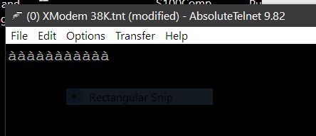
Always the same output. Interesting its always11 characters as well!
If I change the PC terminal baud rate to 57600, Same output but a different trash character.
If I use a 9.2MHz Oscillator and set the PC terminal to 57600 I get the same above character string.
Changing the parity, stop bits etc does not work either.
Somehow the chip is not sending the correct data. I would immediately suspect the hardware or USB interface. But if I use the
SC131-ROMWBW-SC180_131-v320-2023-03-21.ROM software the port behaves completely correctly at 115200.
Unfortunately I'm not knowledgeable at this stage to figure out the exact sequence of codes that must be sent to the
serial A ports to configure it correctly.
Any chance you could test this code on your hardware. If RAM MMU needs to be setup do so, I will just copy your setup.
John
John Monahan
May 12, 2023, 6:51:04 PM5/12/23
to retro-comp
mcmull, I'm using a Z8S180. Also the hardware works fine with the SC131-ROMWBW-SC130xxx.ROM
Wayne Warthen
May 12, 2023, 7:29:03 PM5/12/23
to retro-comp
Hi John,
After adding the following two lines to the top of your code, I got a clean assemble with SLR180. I also converted the format of z180.inc to SLR180.
z180_base equ 0C0H
include z180.inc
include z180.inc
The code worked great on my system. Reliably prints "Hello" every time I power-on or hit reset button.
I am attaching a copy of my .hex file produced by SLR180 in case you would like to compare to yours.
It is hard to imagine you have a hardware problem since RomWBW is working and that is far more complex code.
Thanks,
Wayne
John Monahan
May 12, 2023, 7:34:34 PM5/12/23
to retro-comp
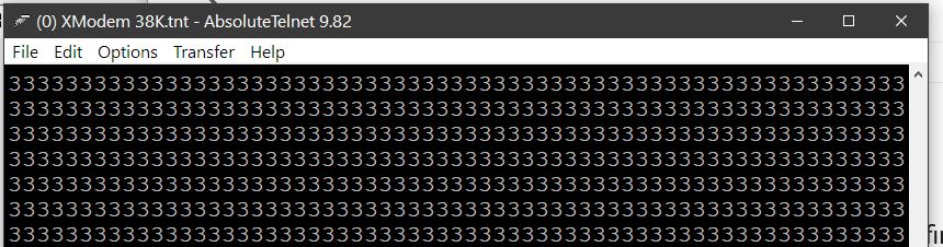
Gentlemen the following worked (at 57600 baud) !!!! Get 3's
OUT0 (CNTLB0),A ; Set Z80180 style baud rates
LD A,14H ; RTS*=1, EFR=0, 8, N, 1
OUT0 (CNTLA0),A
LD A,6CH ; RE, TE, RTS*=0, EFR=1, 8, N, 1
OUT0 (CNTLA0),A
IN0 A,(STAT0) ;C4H,read status
AND 2
ORG 0H
START:
LD A,11000000B ;Move IO_CTL REG to C0-FF Location so we can use low S100 ports
OUT0 (IO_CTL_REG),A ;3FH, Move to C0 to FF. Also IOSTP = 0
LD SP,0B400H ;Where RIZMON.ASM has it
XOR A ; No interupt 57,600 @ 18.432 MHz
START:
LD A,11000000B ;Move IO_CTL REG to C0-FF Location so we can use low S100 ports
OUT0 (IO_CTL_REG),A ;3FH, Move to C0 to FF. Also IOSTP = 0
LD SP,0B400H ;Where RIZMON.ASM has it
XOR A ; No interupt 57,600 @ 18.432 MHz
OUT0 (CNTLB0),A ; Set Z80180 style baud rates
LD A,14H ; RTS*=1, EFR=0, 8, N, 1
OUT0 (CNTLA0),A
LD A,6CH ; RE, TE, RTS*=0, EFR=1, 8, N, 1
OUT0 (CNTLA0),A
LD B,0
DJNZ $
DJNZ $
DJNZ $
DJNZ $
LOOP:
IN0 A,(STAT0) ;C4H,read status
AND 2
JR Z,LOOP
LD A,33H
OUT0 (TDR0),A ;C6H
JP LOOP
No idea why! I t issues a trash character at 115000. Thanks mcmull your code worked. I will explore more.
LD A,33H
OUT0 (TDR0),A ;C6H
JP LOOP
No idea why! I t issues a trash character at 115000. Thanks mcmull your code worked. I will explore more.
Anybody got suggestions of what to sent the MMU registers for a simple Z80 RAM configuration 0-EFFF. Setting the current ROM of 0-7FFFH to F000-FFFFH (ignoring the rest of the ROM block).
John
Wayne Warthen
May 12, 2023, 8:35:35 PM5/12/23
to retro-comp
On Friday, May 12, 2023 at 4:34:34 PM UTC-7 monah...@gmail.com wrote:
Anybody got suggestions of what to sent the MMU registers for a simple Z80 RAM configuration 0-EFFF. Setting the current ROM of 0-7FFFH to F000-FFFFH (ignoring the rest of the ROM block).
Locating physical $00000 at logical (CPU) $F000 is an odd scenario:
Start of Banked Area (BA): $0000 / $1000 = $0
CBAR = $F0
Common Base (CBR): ($00000 - $F000) / $1000 = -$0F ($F1???)
Bank Base (BBR): ($80000 - $0000) / $1000 = $80
CBR comes out as a negative number. You can try $F1 which might work if it wraps around. Here is the incantation:
ld a,0F0h
out0 (cbar),a
ld a,0F1h
out0 (cbr),a
ld a,080h
out0 (bbr),a
In order to make this transition, you will need to do something to avoid losing context. After the transition, do you want to running in ROM or RAM?
Thanks,
Wayne
John Monahan
May 13, 2023, 2:20:16 PM5/13/23
to retro-comp
Again Wayne I will study your suggestion and get back.
Currently the Serial port is initializing and working fine but the RAM access is not. It looks like the SP is not valid. I can get the serial port to output fine if I inline output to the serial port, but if I CALL a Console output routine with a return it fails.
With the following code:-
ORG 0H
START:
IM 1
DI
START:
IM 1
DI
LD A,11000000B ;Move IO_CTL REG to C0-FF Location so we can use low S100 ports
OUT0 (IO_CTL_REG),A ;3FH, Move to C0 to FF. Also IOSTP = 0
XOR A ; Disable refresh
OUT0 (RCR),A ; E6H
XOR A
OUT0 (BCR1L),A ;0DEH, DMA Byte Count Reg Ch 1L
OUT0 (BCR1H),A ;0DFH, DMA Byte Count Reg Ch 1H
OUT0 (RCR),A ; E6H
XOR A
OUT0 (BCR1L),A ;0DEH, DMA Byte Count Reg Ch 1L
OUT0 (BCR1H),A ;0DFH, DMA Byte Count Reg Ch 1H
; set default wait states (super conservative for now)
LD A,0F0H ; +3 mem waits, +3 i/o waits
OUT0 (DCNTL),A ; E3H ;DMA/WAIT Ctl Reg
LD SP,0E000H ;<<<<<<<<<<<
OUT0 (DCNTL),A ; E3H ;DMA/WAIT Ctl Reg
LD SP,0E000H ;<<<<<<<<<<<
; No interrupts, works at 57600 @ 18.432 MHz
XOR A ; PS=0 (/10), DR = /16, SS = /1
OUT0 (CNTLB0),A ; Set Z80180 style baud rates
LD A,14H ; RTS*=1, EFR=0, 8, N, 1
OUT0 (CNTLA0),A
LD A,6CH ; RE, TE, RTS*=0, EFR=1, 8, N, 1
OUT0 (CNTLA0),A
;Some devices where a delay is required after
;configuring the ASCI and before actually trying to send data.
LD B,0 ;Is necessary for for me!
DJNZ $
DJNZ $
LOOP0:
DJNZ $
DJNZ $
LOOP0:
IN0 A,(STAT0) ;C4H,read status
AND 2
JR Z,LOOP0
LD C,33H
OUT0 (TDR0),C ;C6H ---- output is fine
LD HL,0E100H ;RAM
LD (HL),'X' ;Store in RAM
INC HL
LD (HL),'Y'
INC HL
LD (HL),'Z'
INC HL
LD ( HL),'*'
LD HL,0E100H ;RAM
LOOP1:
LD C,33H
OUT0 (TDR0),C ;C6H ---- output is fine
LD HL,0E100H ;RAM
LD (HL),'X' ;Store in RAM
INC HL
LD (HL),'Y'
INC HL
LD (HL),'Z'
INC HL
LD ( HL),'*'
LD HL,0E100H ;RAM
LOOP1:
IN0 A,(STAT0) ;C4H,read status
AND 2
AND 2
JR Z,LOOP1
LD C,(HL)
OUT0 (TDR0),C ;C6H (no 'X' output, not sure why)
INC HL
LD C,(HL)
CALL CO ;No 'X' output
INC HL
LD C,(HL)
CALL CO
INC HL
LD C,(HL)
CALL CO
HALT
CO: in0 a,(STAT0)
and 02H
jr z,CO
out0 (TDR0),C
LD B,0 ;Delay
DJNZ $
RET
LD C,(HL)
OUT0 (TDR0),C ;C6H (no 'X' output, not sure why)
INC HL
LD C,(HL)
CALL CO ;No 'X' output
INC HL
LD C,(HL)
CALL CO
INC HL
LD C,(HL)
CALL CO
HALT
CO: in0 a,(STAT0)
and 02H
jr z,CO
out0 (TDR0),C
LD B,0 ;Delay
DJNZ $
RET
I get continuous 3's.
I need to determine the initial code to change the RAM hardware setup I think from:-
ROM 0-7FFFH
RAM 8000-FFFFH
to
ROM F000-FFFFH
RAM 0-EFFFFH
and relocate the ROM code to F000H-FFFFH.
and adjust the 1MB address space banks to reflect this minimum configuration (can use the rest of the RAM later).
The
reason for all this is a monitor with that configuration would allow
our current "MASTER.Z80" monitor to interface easily with all our current
boards in a Z180 driven S100 bus system (over 50 of them).
A few things, the MASTER monitor only takes up 2K of the ROM, that's why I want it in the top 2k of 64K to run CPM etc. The rest of the current ROM is empty. Thus 2k -> E000H.
I need to relocate that code to valid RAM at E000H and jump to it. Then I need to bank out the RAM at 0-7FFFH and have RAM 0-EFFFH.
That is the configuration that we have be using for over 10 years and allows must of our S100 bus software/hardware to work unchanged.
I really need help configuring the Z180 to this format. Hopefully that would solve the above code problem.
John
John Monahan
May 13, 2023, 6:34:05 PM5/13/23
to retro-comp
Wayne I going to see if I can better explain what I'm trying to do as the above postings are not clear.
Because I suspect I must have a valid RAM setup to do the following.
In the Z180 S100 board I wish to end up with a small 4K
monitor in RAM at F000-FFFFH. The rest (0-EFFFH), is to be used as general use RAM.
In the F000-FFFFH RAM is a "warmed over" MASTER.Z80 monitor with just the console going
to the serial A port on the Z180. This way, one could interface the
~50 S100 boards we have built over the past 12 years, run CPM etc with little changes. That
MASTER monitor has been tweaked many many times and is rock solid now.
I don't want to go to something new/unknown in such a system.
The
challenge is the adjust the Z180 MMU registers so that the hardware ROM
0-7FFFFH (with relevant ROM code only at 0-0FFFH, the rest unused) and hardware RAM at
80000H-FFFFFH converts into RAM 0-FFFFH and the ROM code at 0-0FFFH is
moved to F000H-FFFFH in that space. The rest of the Z180's Address
space does not matter at this stage.
I really could use your knowledge in how to configure the 3 Z180 MMU registers to get the above arrangement. How close is the code you have above to ending up with the required arrangement.
Does the above make sense. Is there any way you could test such a layout in one of your systems.
John
Message has been deleted
John Monahan
May 13, 2023, 6:50:08 PM5/13/23
to retro-comp
Two more things. I could repeat the monitor code block anywhere in the 512K ROM if that would help.
Clearly
I need to do things in two steps. Setup the MMU registers. Move the ROM
code at 0-1FFFH to E000-FFFFH, jump to it an then from there eliminate
the whole ROM in low memory (0-7FFFH) an replace it with MMU RAM.
Currently all this is above my pay grade!
John
Bill McMullen
May 15, 2023, 4:40:45 PM5/15/23
to retro-comp
John: Good to see that you're getting the expected results at 57600. Slow reply and I hadn't realized you were using clock/2 for PHI and thus 115200 won't work at 9.216MHz & /16 with either the basic baud generator or the Z8S180 BRG.
Per your your link to retrobrewcomputers in the comments about setting CMR before CCR: Those are my words and I experienced that on quite a few different physical chips and mask revisions although offhand I can't remember whether that was using an oscillator and/or crystal input for the clock ... I've used both in various designs, usually at 16.667*2 or 18.432*2 MHz. That warning is meant for XTAL*2 not XTAL/2 per your reference (i.e. it's for updating to input = PHI/2).
Bill
Wayne Warthen
May 15, 2023, 5:02:03 PM5/15/23
to retro-comp
On Monday, May 15, 2023 at 1:40:45 PM UTC-7 mcmull...@gmail.com wrote:
Per your your link to retrobrewcomputers in the comments about setting CMR before CCR: Those are my words and I experienced that on quite a few different physical chips and mask revisions although offhand I can't remember whether that was using an oscillator and/or crystal input for the clock ... I've used both in various designs, usually at 16.667*2 or 18.432*2 MHz. That warning is meant for XTAL*2 not XTAL/2 per your reference (i.e. it's for updating to input = PHI/2).
Hi Bill,
That comment came from RomWBW source code. Thank you for pointing out the error. I will correct the comment in RomWBW. There is a link to your original comment in the source code, but I will add something to credit you directly.
Thanks,
Wayne
Bill McMullen
May 15, 2023, 7:26:01 PM5/15/23
to retro-comp
No problem Wayne. I believe that tidbits (errata?) like that should be openly shared among retro enthusiasts and I don't feel any need to receive credit for them. Then again, I've also been known to be wrong before ... LOL
A couple more Z8S180 quirks I found:
The Z8S180 User Manual clearly shows ASTCxH/L being set to zero upon reset (pg 137-138) which is easily verified by reading them. At faster ASCI rates only the low register needs to be changed. However, if the high register is not rewritten to zero then no communication occurs. The solution is to always write both the high and low registers when initializing the Z8S180 BRG.
Another Z8S180 issue I found relates to the use of a crystal versus an oscillator. The SLP instruction reduces power consumption and works as expected on boards which use a crystal but simply acted as a NOP when using an oscillator on the boards I tested. The solution is to use HALT rather than SLP on boards that use an oscillator.
Wayne Warthen
May 15, 2023, 7:54:12 PM5/15/23
to retro-comp
On Monday, May 15, 2023 at 4:26:01 PM UTC-7 mcmull...@gmail.com wrote:
No problem Wayne. I believe that tidbits (errata?) like that should be openly shared among retro enthusiasts and I don't feel any need to receive credit for them. Then again, I've also been known to be wrong before ... LOL
I feel the same way and frequently just assume others feel the same as me. It is better to actually check!
A couple more Z8S180 quirks I found:
The Z8S180 User Manual clearly shows ASTCxH/L being set to zero upon reset (pg 137-138) which is easily verified by reading them. At faster ASCI rates only the low register needs to be changed. However, if the high register is not rewritten to zero then no communication occurs. The solution is to always write both the high and low registers when initializing the Z8S180 BRG.
Good to know. I have (thus far) stayed away from the use of the BRG simply because people frequently fail to get the latest version (Rev. N) chip. As far as I know, only Rev. N supports the BRG.
Another Z8S180 issue I found relates to the use of a crystal versus an oscillator. The SLP instruction reduces power consumption and works as expected on boards which use a crystal but simply acted as a NOP when using an oscillator on the boards I tested. The solution is to use HALT rather than SLP on boards that use an oscillator.
Also good to know.
Thanks,
Wayne

William Hickey Jr
Sep 14, 2023, 3:19:10 PM9/14/23
to retro-comp
I have a handful of these boards using the HD64180 and a very common memory map,

I'd like to load BASIC on it but need to reconfigure the code for the on board UART(1).
It looks far more tricky than the MOTO stuff I used prior. The clock is 12.288Mhz.
I'm following the issue above but do not see the Windows assembler you are using for the code snippets.
What is being used on this chain?
Many thanks!
Wayne Warthen
Sep 14, 2023, 3:47:34 PM9/14/23
to retro-comp
On Thursday, September 14, 2023 at 12:19:10 PM UTC-7 william...@gmail.com wrote:
I have a handful of these boards using the HD64180 and a very common memory map,I'd like to load BASIC on it but need to reconfigure the code for the on board UART(1).It looks far more tricky than the MOTO stuff I used prior. The clock is 12.288Mhz.I'm following the issue above but do not see the Windows assembler you are using for the code snippets.What is being used on this chain?
The Windows hosted Z80 assembler I used is TASM. You will find a full copy of the TASM v3.2 distribution included in RomWBW at https://github.com/wwarthen/RomWBW. It is found in the Tools/TASM32 folder.
Thanks,
Wayne

Greg Holdren
Sep 15, 2023, 12:46:31 AM9/15/23
to retro-comp
William,
Here is a code snippet for the Hitachi serial port init for my HD64180 board that uses the 12.288MHz xtal. This might help along with the data manual for the 64180.
cstart: LD A,04H ;status register: RX Int Enabled, port 1
OUT0 (0005H),A ;
LD A,74H ;ASCI control register A: rx/tx en, 8N1 bits
OUT0 (0001H),A ;
LD A,00H ;ASCI control register B: set for 38.4Kbps
OUT0 (0003H),A ;
LD A,04H ;status register: RX Int Enabled, port 0
OUT0 (0004H),A ;
LD A,6ch ;ASCI control register A: rx/tx en, 8N1 bits
OUT0 (0000H),A ;
LD A,00H ;ASCI control register B: set for 38.4Kbps
OUT0 (0002H),A ;
Greg
On Thursday, September 14, 2023 at 12:19:10 PM UTC-7 william...@gmail.com wrote:
William Hickey Jr
Sep 15, 2023, 12:30:12 PM9/15/23
to retro-comp
Thank you very, very much!
Reply all
Reply to author
Forward
0 new messages