Issues interfacing a Z80 to a Raspberry Pi Pico
903 views
Skip to first unread message

Dylan Hall
Jun 25, 2021, 8:55:54 AM6/25/21
to retro-comp
Hi all, first time posting :)
I've also connected a couple of the digital pins to the same points with the software set to TTL mode which seems to use 1.5V as it's threshold.
I think I'm having some sort of problem where my signals from the bus are very noisy and I'm realising I'm out of my depth trying to figure out why.
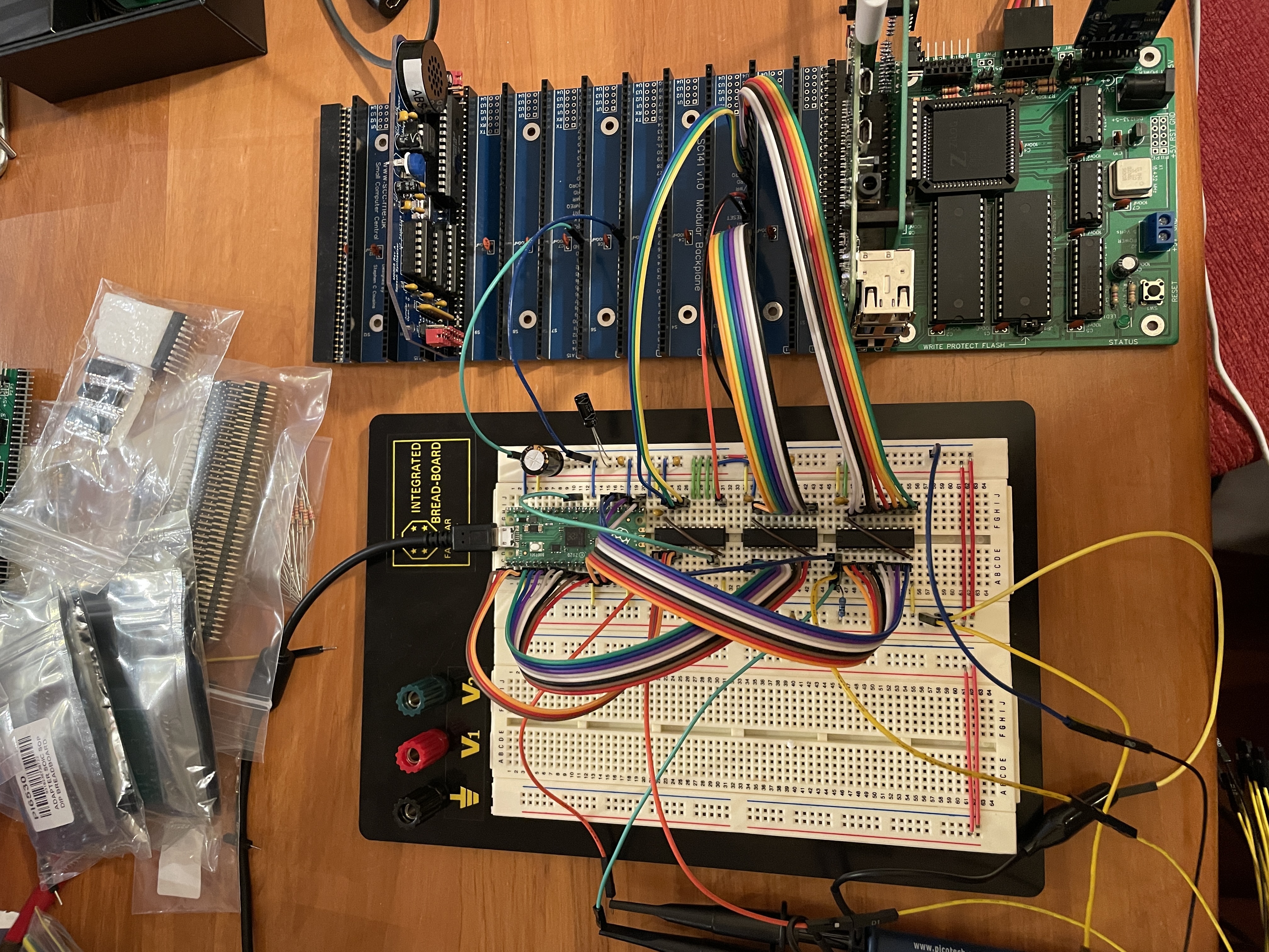
A bit of background first. I have the eventual goal of interfacing my SC130 to a Raspberry Pi so the Pi can provide storage. I've gone down the rabbit hole of sticking a Raspberry Pi Pico between the two as I decided the GPIO pins on the Pi are too slow. The Pico on the other hand has the new PIO state machines which are very quick and a lot fun to tinker with :)
I have the Pico connected to the bus via three 74LVC245 chips to provide translation from 5V to 3.3V. The first chip is handling IORQ, RD, and WR. The second a0-a7, and the third d0-d7.
I've reached the point where I have the Pico recognising the IO requests (either IORQ + WR + address or IORQ + RD + address). Reading from the bus (e.g. z80 OUT) seems pretty reliable but writing to the bus is proving a bit flaky (e.g. z80 IN). I'm testing from mbasic with simple OUT and INP commands. I'm able to crash mbasic intermittently with the INP commands which I suspect is the Pico/74LVC245 not giving the data pins back quick enough after the IO request finishes.
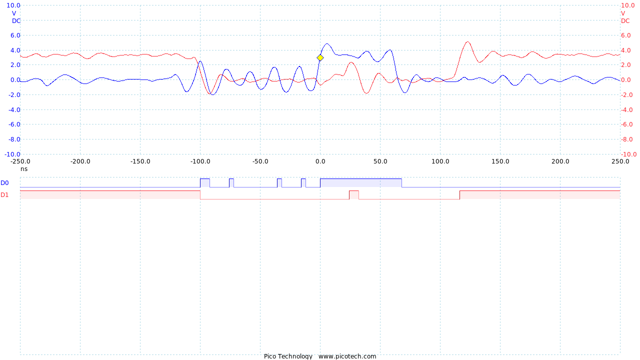
Trying to establish where I'm going wrong I've stuck a scope on the IORQ pin (the 3.3V side of the 74LVC245, shown in red) and the direction pin of the 74LVC245 that is connecting the Pico to the data pins (shown in blue). When the Pico sees the request it pulls the direction pin high before writing the answer to the bus. I'm using this as my trigger.
I've also connected a couple of the digital pins to the same points with the software set to TTL mode which seems to use 1.5V as it's threshold.
I don't know what these signals should look like, but my guess here is that is far noisier than it should be. I'm testing this on a breadboard with lots of unshielded cables so I'm wondering if I'm asking too much of it?
I've got 0.1uF caps as close to the power supply pins as I can get them. I've tied the unused inputs on the 74LVC245's to ground (after initially forgetting). I've tried an alternative power supply for the 3.3V wondering if I'm picking up noise from the switch-mode regulator in the Pico. None of this has made any significant difference.
I have a Raspberry Pi 4 very close to the board providing me SSH over WIFI to serial for controlling the SC130. Could I be picking up interference from the Pi?
I have the software almost working but I can't tell if my remaining issues are software or hardware so I'm reluctant to go to the next step of making a PCB until I have some idea what's going on.
Any thoughts or suggestions would be much appreciated.
Thanks,
Dylan

Mark T
Jun 25, 2021, 11:46:50 AM6/25/21
to retro-comp
The noise on the signals is at a time where the z80 does not really care whats on the data bus. The noise is quite bad, changing the logic level, but I don’t think thats your problem.
It looks like you are changing the direction control on the 245 before the end of the IORQ bus cycle, so the data bus might no longer contain the data you want the z80 to input. You could try keeping the direction control active slightly longer, but then you might have a problem with bus contention if you are driving the bus past the end of IORQ.
Can you post a schematic of the interface?
You could probably control the enable of the 245 from the z80 to avoid bus contention.

Bill Shen
Jun 25, 2021, 1:35:41 PM6/25/21
to retro-comp
You need more ground return from your breadboad to RC2014 backplane. 74LVC245 has 8 fast, high current drivers and you are counting on the ground wire to hold up the voltage when up to 24 signals are changing swiftly. Add two more ground wires will improve your noise problems.
Keep the scope ground wire as short as possible; move the ground point to ground on RC2014 backplane.
Bill
Dylan Hall
Jun 27, 2021, 5:28:52 AM6/27/21
to retro-comp
Thanks for the feedback Mark and Bill :)
Mark - diagram attached of the setup on the breadboard at present. I've left off the caps for now. You're right, I'm cutting short the direction control. After your comment I went back to the code and realised I'd taken the screen shot while I was experimenting with the length of the direction control to see if that stopped mbasic from crashing. It didn't stop the crashes so I was wondering if the noise on the control line was causing the 245 to toggle direction randomly after the IO request should have finished. More experiments required.
The other area I want to tinker is replacing the 245 for the control signals with a couple OR gates or a 138 so I can present a simpler IO_RD and IO_WR controls to the Pico so the code doesn't have to test the IORQ and RD or WR pins at the same time. I'm just waiting on some LVC versions of the parts to arrive.
Bill - I had 4 jumpers connecting ground from the breadboard to the SC130. I've added a couple more and moved them around a bit so there's one from each of the ground pins on the 245's back to the bus. I think that's helped a little but not as much as I was hoping. Is it the length or the gauge of the jumpers that matters? I ask because I'm wondering if my very cheap/flimsy jumpers would be better replaced with something more robust. Also, is there a name for this issue? I'd like to go Google it and understand it better.
Thanks,
Dylan
Bill Shen
Jun 27, 2021, 8:22:41 AM6/27/21
to retro-comp
On Sunday, June 27, 2021 at 3:28:52 AM UTC-6 Dylan Hall wrote:
Bill - I had 4 jumpers connecting ground from the breadboard to the SC130. I've added a couple more and moved them around a bit so there's one from each of the ground pins on the 245's back to the bus. I think that's helped a little but not as much as I was hoping. Is it the length or the gauge of the jumpers that matters? I ask because I'm wondering if my very cheap/flimsy jumpers would be better replaced with something more robust. Also, is there a name for this issue? I'd like to go Google it and understand it better.
The problem of ground shifting due to faster drivers switching is called "ground bounce". Older DIP TTL logic didn't have this problem (at least it was not easily observed), but newer, faster octal driver of 1980's like IDT's FCT family have raised the issue. It was one of the reasons for moving away from DIP package and going for smaller SMT package, some even with VCC/GND in center pins. The important point is reducing the inductance of the ground return, so multiple returns with shorter wires are helpful.
IMO, simultaneously switching multiple fast octal drivers in a breadboard setup is a tough problem to solve.
Bill
Mark T
Jun 27, 2021, 2:23:20 PM6/27/21
to retro-comp
You might also try 74AHC logic powered from 3.3v. Inputs would be compatible with TTL logic levels and 5v tolerant. It might be easier to find 74AHC in DIL packages.
I would suggest changing OE of U3, so it is active low only for a smaller range of addresses, then it will probably be easier to share the bus with other RC2014 modules.
Please stop using that method of drawing schematic with every signal in and out of a common bus. If you really must use a bus in the schematic then use a separate bus for each function that makes sense to be a bus. Example address bus, data bus, 3.3v data bus, etc.
Dylan Hall
Jun 28, 2021, 8:55:41 AM6/28/21
to retro-comp
I've made some nice progress tonight thanks to your suggestions :)
I've shortened the leads to the scope probes. I had another think about the ground wires and realised I had lots between the 245's and the z80 bus but not to the Pico so I've fixed that. I was also concerned the bypass caps weren't close enough to the 245's so I've soldered them directly to top of the chips. Lastly, I've connected the OE on the address and data 245's to the IORQ line so the chips aren't active the whole time. The upshot is much cleaner looking plots on the scope.
I've then put some effort into the code on the Pico and I figured out what was causing the random crashes. Mostly for debugging purposes I have the state engine that's handling IN commands from the z80 push the address it reads from the bus up to the CPU for printing to the console. The "push" command that handles this blocks if the FIFO between the state machine and the CPU is full. As it turns out the FIFO was full quite often as the print command had lots of fancy formatting so was rather slow to empty the FIFO. When the state machine stalled it would fail to toggle the direction pin on the data 245 back into a safe position before the IO request finished causing contention which fairly reliably crashed mbasic. Adding a "noblock" to the push command was an easy fix :)
The next step is putting the OE pins under control of the Pico so I can only enable the address 245 at the start of the IO request when I need the address and only enable the data 245 in the second half if the address matches one I'm looking for.
Lastly, thanks for the feedback about the diagram Mark. It's the first time I've used the bus feature and the result was pretty awful. Something to think about for version 2 :)
Again, thanks for your help, it's much appreciated.
Dylan

John Kennedy
Jun 28, 2021, 11:08:33 AM6/28/21
to retro-comp
This is very neat. Hope you get it working. I love the idea of using a Pico as a ROM/RAM/IO system for a Z80. I would add something on this to my S-100 system for fun.
Reply all
Reply to author
Forward
0 new messages