Hardware debugger
123 views
Skip to first unread message

Tadeusz Pycio
Nov 1, 2021, 5:22:42 AM11/1/21
to retro-comp
Have any of you gone into building or have knowledge of the best way to make a hardware debugger? Processor emulation, limits to specific only. RAM emulation or "simplest" bus monitor are the most versatile. I care about code tracing, address traps, data traps, and triggering from a specific condition. I'm starting to work on building such a device and wouldn't want to go in blind. My tools have failed when it comes to multithreading, the software debugger interferes too much. Other ideas?

Dylan Hall
Nov 1, 2021, 6:06:00 AM11/1/21
to Tadeusz Pycio, retro-comp
I've been making slow progress connecting a Raspberry Pi Pico to the z80 bus so it can act as an I/O device. My goal wasn't to build a debugger but with tweaks to the code it could snoop I/O events (it can watch and optionally respond to events from any address).
I've just started my next iteration where I want the Pico to function as memory for the z80. It's early days so I don't have anything to show yet, but if the Pico is responding to memory read and write requests I suspect that could be hijacked to act as a debugger of sorts.
If any of that sounds useful I'm happy to share what I have and the many pitfalls I've encountered on the way :)
Dylan
On Mon, 1 Nov 2021 at 22:22, Tadeusz Pycio <ta...@wp.pl> wrote:
Have any of you gone into building or have knowledge of the best way to make a hardware debugger? Processor emulation, limits to specific only. RAM emulation or "simplest" bus monitor are the most versatile. I care about code tracing, address traps, data traps, and triggering from a specific condition. I'm starting to work on building such a device and wouldn't want to go in blind. My tools have failed when it comes to multithreading, the software debugger interferes too much. Other ideas?
--
You received this message because you are subscribed to the Google Groups "retro-comp" group.
To unsubscribe from this group and stop receiving emails from it, send an email to retro-comp+...@googlegroups.com.
To view this discussion on the web visit https://groups.google.com/d/msgid/retro-comp/c8002e43-1625-402c-b7e5-1c2724ed43e2n%40googlegroups.com.
Tadeusz Pycio
Nov 1, 2021, 6:48:01 AM11/1/21
to retro-comp
Hi Dylan,
This is a great idea! I don't know why, but I never considered using a modern microcontroller in my ideas. I guess I have too much exposure to retro hardware. :(
You reminded me that something like this was made, but I don't think it was made public: https://www.youtube.com/watch?v=Gdode3PfTbs
This is a great idea! I don't know why, but I never considered using a modern microcontroller in my ideas. I guess I have too much exposure to retro hardware. :(
You reminded me that something like this was made, but I don't think it was made public: https://www.youtube.com/watch?v=Gdode3PfTbs

David Richards
Nov 1, 2021, 7:05:15 AM11/1/21
to retro-comp
The retroshield project may be of interest as it performs a similar purpose interfacing to a microprocessor and emulates memory and i/o devices. see here: http://www.8bitforce.com/projects/retroshield/
I have tried to use it to exercise a soviet pdp11 clone cpu but without complete success possibly due to poor level conversion between the 3v3 and 5v systems.
How do you cope with the logic level translations between the pico and Z80?
I have another wish to someday be able to add real peripherals onto a cpu core emulated on a fpga, I'm sure many of the pitfalls are similar.
Kind regards, David.
Tadeusz Pycio
Nov 1, 2021, 7:24:14 AM11/1/21
to retro-comp
How do you cope with the logic level translations between the pico and Z80?
A good entry point might be the converter used here, for example: https://github.com/hoglet67/AtomBusMon
Dylan Hall
Nov 1, 2021, 7:54:19 AM11/1/21
to Tadeusz Pycio, retro-comp
On Tue, 2 Nov 2021 at 00:24, Tadeusz Pycio <ta...@wp.pl> wrote:
How do you cope with the logic level translations between the pico and Z80?A good entry point might be the converter used here, for example: https://github.com/hoglet67/AtomBusMon
As a newbie in just about every aspect of this project I resorted to Google and found the 74LVC series of parts. These are 3.3V logic gates and buffers that are 5V tolerant. E.g. they'll translate 5V -> 3.3V but not the other way.
I'm using the 74LVC245 bi-directional buffer to connect address and data lines and regular AND/OR/etc gates for the various control pins.
I also briefly tried the 74LVC4245 which does up translation (3.3V -> 5V) as well.
However, I've hit all manner of little niggly issues using the LVC series. Essentially they're too fast. Their transitions between low and high cause bouncing with other parts on the same PCB. The '4245 was the worst, each time it drove the data bus other chips would toggle their state with apparent ground bounce like issues (all this is new to me so I may well have this wrong!).
The other downside is most of the parts are only available in surface mount packages.
In the last couple of days I've been trying the 74AHC series instead on the same PCB. These parts support 2-6V (e.g. are happy at 3.3V), have 5V tolerant inputs, and operate at about half the speed. My initial tinkering suggests they're working much better.
As an example of an issue, I'm using a 74LVC139 to decode IORQ and M1 into "IORQ and not M1", "M1 and not IORQ", and "INT_ACK" (interrupt acknowledge, IORQ and M1).
It turns out at the end of an interrupt request cycle IORQ and M1 don't return to high at quite the same time, there is maybe a 4ns gap between them. Annoyingly this is enough for the '139 to switch outputs which in turn triggers the Pico into thinking an I/O request is underway.
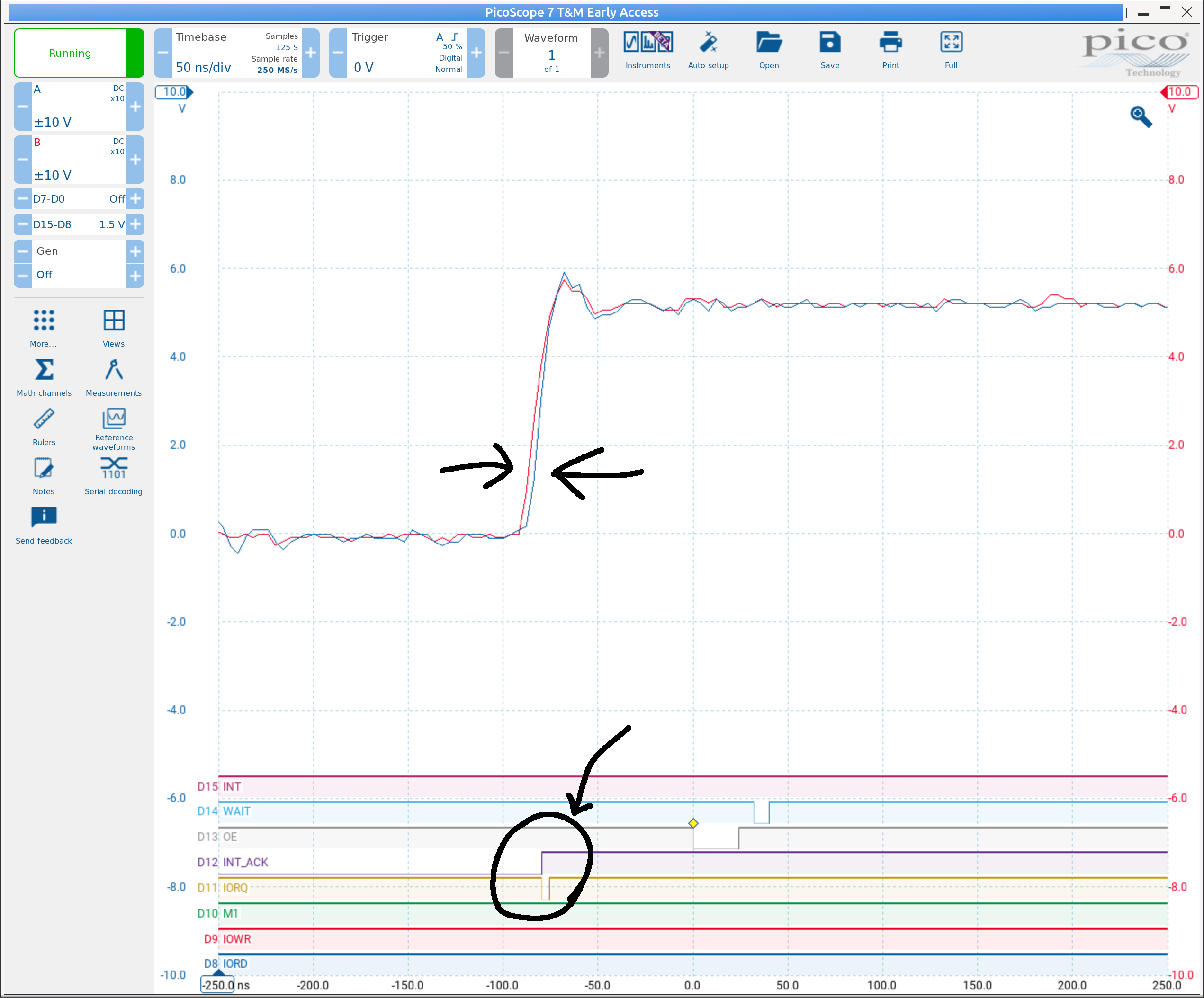
The analog traces at the top show M1 and IORQ while the digital traces (circled) show INT_ACK and IORQ_and_not_M1.
The ACH part doesn't appear to be fast enough to react to the lag.
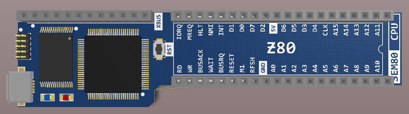
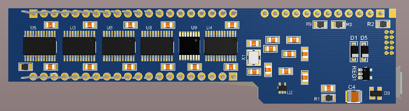
Full schematic of my current prototype attached.
Dylan

Alan Cox
Nov 1, 2021, 8:33:51 AM11/1/21
to Tadeusz Pycio, retro-comp
On Mon, 1 Nov 2021 at 09:22, Tadeusz Pycio <ta...@wp.pl> wrote:
Have any of you gone into building or have knowledge of the best way to make a hardware debugger? Processor emulation, limits to specific only. RAM emulation or "simplest" bus monitor are the most versatile. I care about code tracing, address traps, data traps, and triggering from a specific condition. I'm starting to work on building such a device and wouldn't want to go in blind. My tools have failed when it comes to multithreading, the software debugger interferes too much. Other ideas?
I build a full software emulation for the system usually, and include full instruction tracing so that I can run the system for a bit, capture the instruction flow and then analyse it. In part it's just how I was used to doing it in a work environment for many years. Some of the professional tools embed things like python in them so you can write quite complex rule sets for trapping and tracing but my Z80/Z180 etc emulations I keep easy to modify and just hack the C code temporarily for whatever I need.
For hardware I'm using things like a bitscope and bus pirate but the bitscope isn't up to tracing higher speed stuff and now I'm trying to build a Z180 mini-ITX design it's not really up to that job.
On FPGA it was easier - there are FPGA designs for things like logical analyzers and you just compile one into your FPGA along with the rest of your system.
Alan

Rob Gray
Nov 1, 2021, 9:25:34 AM11/1/21
to retro-comp
I love the idea and have some form in emulator design, albeit many years ago.
I started work on a simple design a while back but won't continue with it I think.

J.B. Langston
Nov 1, 2021, 10:14:14 AM11/1/21
to retro-comp
I have done this with z80ctrl. I am not emulating the processor but I control the clock and sample the bus on each clock tick. It has break points and watch points on memory or IO access or instruction fetches from specified address ranges. The code for the debugger is here: https://github.com/jblang/z80ctrl/blob/master/firmware/z80.c#L142

Frank P.
Nov 1, 2021, 11:22:04 AM11/1/21
to retro-comp
I've used either these: https://www.amazon.com/gp/product/B07LG646VS/ (you get 4 per package)
Or (even simpler) SN7406 TTL logic chips (6 open collector inverters). In the case of the 7406, use 1K pullups on the collectors to either 5V (for 5V output) or 3.3V (for 3.3V output). The inputs register high with anything over 2V, so that works fine with either 3.3V or 5V. I'm sure any variant of the 7406 (5406, 5416, 7416, 74LS06, etc.) would work fine. If you don't want inverting, use the 7407 series instead.
Don't know if any of these solutions is "too fast", but there's not much a good decoupling cap won't fix.

Mark T
Nov 1, 2021, 11:33:58 AM11/1/21
to retro-comp
Hi Dyan,
This is not quite the classic different clock domains problem, as the asynchronous delays in the z80 from clock edges are so slow. If you register the control signals on the z80 clock you would probably need to slow down the z80 clock.
You could consider using a bistable latch for glitch free decoding. In the case of INTACK, use an AND-OR bistable latch, perhaps using 74LVC1G0832, M1 to the OR gate input, IORQ to one AND gate input and the output feeds back to the other AND gate input. The feedback adds memory which avoids the glitch.
Mark
Tadeusz Pycio
Nov 1, 2021, 1:42:23 PM11/1/21
to retro-comp
I have done this with z80ctrl. I am not emulating the processor but I control the clock and sample the bus on each clock tick. It has break points and watch points on memory or IO access or instruction fetches from specified address ranges. The code for the debugger is here: https://github.com/jblang/z80ctrl/blob/master/firmware/z80.c#L142
That's a good idea, especially since I have one blank PCB that I can modify so that the CLK goes not to the bus, but to the clock input on the Z180. "The best place to hide something is in plain sight". I'll try that.
There are also a lot of interesting ideas, I thought this topic was of interest to few, I was wrong.
There are also a lot of interesting ideas, I thought this topic was of interest to few, I was wrong.

Bill Shen
Nov 1, 2021, 10:40:02 PM11/1/21
to retro-comp
I have prototyped a diagnostic module for RC2014 based on CPLD. It was a simple idea based on slowing down the system clock so address/control/data can be captured and sent serially at 460800 or faster. This approach can't run at full speed because it can't sent serial data out fast enough. However, if the diagnostic module has local storage such as a repurposed ZRC (with Z80 removed) which has 2meg of storage, then it can monitor the bus at full speed then send data out serially once desired data are captured. Processing that amount of data can be challenging, however.
Bill
Bill
Reply all
Reply to author
Forward
0 new messages