Skip to first unread message

Bill Shen
Jun 20, 2019, 7:02:30 PM6/20/19
to SBC-Z80
Look what shows up in the afternoon mail! 10x Z84C1516 from UTSource for $52. This is 16MHz Z80 with integrated KIO (SIO/CTC/PIO) in relatively easy-to-solder QFP100 with 0.65mm pitch. Should be able to build very compact Z80 SBC with SMT EEPROM, RAM and micro SD card. I'm thinking of putting it in the $2 Arduino R3 enclosure, or the larger $3 Arduino Mega2560 Uno enclosure, with the backside completely covered with SMT LEDs driven by PIO. A brash show piece, very American!
Bill
Bill

Greg Holdren
Jun 20, 2019, 7:57:15 PM6/20/19
to SBC-Z80
Droooling!
Greg

Sergey Kiselev
Jun 20, 2019, 8:18:23 PM6/20/19
to SBC-Z80
I was eyeing that Z84C15 too... Mouser also stocks them, although they are quite a bit more expensive there.
Unfortunately it doesn't offer SPI interface (which would simplify SD card interface implementation). But then you can bitbang it using PIO.
Yes for everything SMT, except of the EEPROM/Flash... If you really want, you can use PLCC, but it is almost impossible to solder SMT PLCC sockets manually, THT PLCC sockets would work. Also extracting PLCC ICs from sockets is a major PITA even when using PLCC extraction tool. So can we have PDIP-32 39SF040 please?
It is possible to modify my Easy Z80 design, substitute Z80 CPU/CTC/SIO with Z84C15, use SMD components all around, add an FT231 and a Micro/Mini USB connector for serial console on the first SIO port and a pin header for the second port.
I think all this will fit on an 5 x 10 cm board, or if you don't want to stick to RC2014 format, a credit card sized board would be fun.
On Thursday, June 20, 2019 at 4:02:30 PM UTC-7, Bill Shen wrote:

Richard Lewis
Jun 20, 2019, 9:15:21 PM6/20/19
to SBC-Z80
The reason I didn't pick one up on Mouser is that they are around $16 each. I'm putting together an all SMD board and bought the CPU/PIO/SIO/CTC as separate QFP-44 chips: Z84C0010, Z84C2010, etc Together it was around $20 for the set but I figured if I screwed up 1 I was only out $5. For the SPI interface I am either going to use a CPLD or this ATtiny1614 (I picked up 10 the other day). The cool thing about this MCU is that it can run on 5V, is a recently new part, has built-in SPI, I2C peripherals and has programmable logic!! So these would make perfect, clock generator, SPI master, glue logic chips all in 1 package.
I'm only able to consistently solder an SMT PLCC socket using paste and an oven. I was successful manually soldering one once with an 1mm bent hakko tip but was too tedious.
Richard Lewis
Jun 20, 2019, 9:20:03 PM6/20/19
to SBC-Z80
Hi Bill, When you buy them like this do you get any that are non-functioning? Or have they been tested by the vendor and certified? What would really be cool would be a "Zeduino"
On Thursday, June 20, 2019 at 4:02:30 PM UTC-7, Bill Shen wrote:
Bill Shen
Jun 20, 2019, 10:21:13 PM6/20/19
to SBC-Z80
Sergey,
I have a K80 design ( https://www.retrobrewcomputers.org/doku.php?id=builderpages:plasmo:k80 ) that I can basically replace the Z80 & KIO with a Z84C15. In the meantime it also serves as a platform to develop software for Micro80.
There are some interesting works out there using four Z80 signals to load bootstrap code into RAM from initial power up. I think it would be interesting to use that method to boot up the very first time and load code into RAM which then program the EPROM. This way EPROM can be soldered down directly without socket and programmed later.
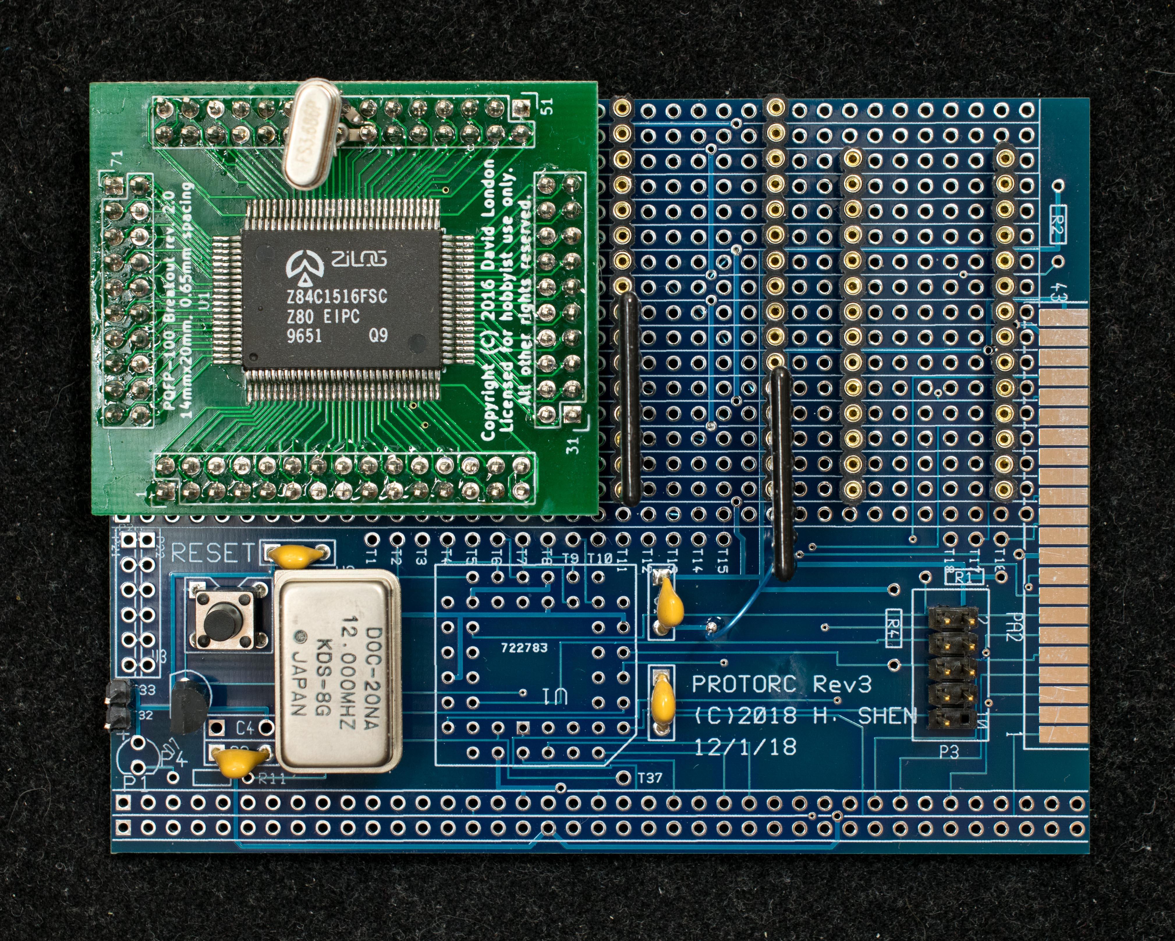
With some practice, it is possible to solder SMT sockets to existing PLCC footprint. Attached is the photo of my Zuno (Z80 for Arduino) test board that has two SMT PLCC sockets. I applied solder flux to the pads first and let it dried and became tacky. Center the socket and carefully solder the first pad with a fine bent solder tip using very fine solder (0.23mm). Once the first pad is centered correctly, the rest became easier. I also plan to redesign the SMT footprint so each pad is longer to provide a landing zone for solder tip. I think the combination of better PLCC footprint, fine solder, fine solder tip, and practice, practice, practice, should make SMT socket easier to solder.
Bill
I have a K80 design ( https://www.retrobrewcomputers.org/doku.php?id=builderpages:plasmo:k80 ) that I can basically replace the Z80 & KIO with a Z84C15. In the meantime it also serves as a platform to develop software for Micro80.
There are some interesting works out there using four Z80 signals to load bootstrap code into RAM from initial power up. I think it would be interesting to use that method to boot up the very first time and load code into RAM which then program the EPROM. This way EPROM can be soldered down directly without socket and programmed later.
With some practice, it is possible to solder SMT sockets to existing PLCC footprint. Attached is the photo of my Zuno (Z80 for Arduino) test board that has two SMT PLCC sockets. I applied solder flux to the pads first and let it dried and became tacky. Center the socket and carefully solder the first pad with a fine bent solder tip using very fine solder (0.23mm). Once the first pad is centered correctly, the rest became easier. I also plan to redesign the SMT footprint so each pad is longer to provide a landing zone for solder tip. I think the combination of better PLCC footprint, fine solder, fine solder tip, and practice, practice, practice, should make SMT socket easier to solder.
Bill
Bill Shen
Jun 20, 2019, 10:45:30 PM6/20/19
to SBC-Z80
Richard,
UTSource has been very reliable. They have a $1 "money back insurance" you can buy which I do buy when getting a new part, but I have never ever exercised that insurance for the thousands $$$ purchases I made over the years. Having said that, I'm building up a breadboard to test the part, right now.
Bill
PS, "Zeduino" is a bit of tongue twister, I called mine "Zuno"

Richard Deane
Jun 21, 2019, 2:34:09 AM6/21/19
to retro-comp
The one inch square pcb for cpm50mk2 in hackaday is very interesting
50mhz ez80 with assist from zilog support chip. Just needs someone to make a little more expendable rc2014ish. It's by jessexm. I assume the license would allow that. I am considering making one as smd soldering practice, price of components on mouser approx 25$.
50mhz ez80 with assist from zilog support chip. Just needs someone to make a little more expendable rc2014ish. It's by jessexm. I assume the license would allow that. I am considering making one as smd soldering practice, price of components on mouser approx 25$.
Message has been deleted
Bill Shen
Jun 23, 2019, 6:10:09 PM6/23/19
to retro-comp
Wired up the Z84C1516 to do the "NOP/free run" test by pulling down the data lines. All addresses are incrementing as expected. Nominal power consumption is 40mA at 12MHz. The value is consistent with the data sheet. I'm encouraged by this test, and will proceed to breadboard up a SBC with RAM & EPROM.
Bill
Bill
Bill Shen
Jun 24, 2019, 9:20:56 AM6/24/19
to retro-comp
Micro80 is alive! As the pictures showed, it is a very simple design, just RAM, ROM, 74LS32, and Z84C1516. The separate oscillator is not necessary, it is added so CPU clock can be independent from the serial ports for evaluation purpose.
Bill
Bill
Greg Holdren
Jun 24, 2019, 12:43:44 PM6/24/19
to retro-comp
I'll take 10. Looks good.
I prefer separating serial and CPU clocks in designs any ways. More flexible.
Greg

Alan Cox
Jun 25, 2019, 12:53:47 PM6/25/19
to retro-comp
On Monday, 24 June 2019 17:43:44 UTC+1, Greg Holdren wrote:
I'll take 10. Looks good.
Need them all to talk to each other though - then you can build one of these
8)

Tom Storey
Jun 25, 2019, 1:01:53 PM6/25/19
to Alan Cox, retro-comp
That sorta sounds like the transputer.
Bill Shen
Jun 25, 2019, 1:19:24 PM6/25/19
to retro-comp
From array of Z80 to Artificial Intelligence in a single bound! As we engineers often have said: "Anything is possible as long as I don't have to do it". Two processor prototype had $120K hardware budget! Probably spend more money on the communication ring than the processor/memory.
Bill
Bill
Bill Shen
Jul 8, 2019, 12:08:55 AM7/8/19
to retro-comp
Add a compact flash interface to Micro80. The internal SIO/CTC/PIO I/O addresses are hardwired to 0x10-0x1F, so I wire CF I/O address to 0x90-0x97. CP/M2.2 is ported successfully. The Z84C1516 is rated at 16MHz but I tried several higher clocks to find out the design margin. It will not boot at 29.5MHz; will boot OK at 28.8MHz, but compact flash is not working. At 24MHz it is working quite well, passing zexall.com test without any errors. Power consumption is 90mA@5V at 24MHz.
Bill
Bill
Greg Holdren
Jul 9, 2019, 12:01:15 AM7/9/19
to retro-comp
Bill,
That looks great! Will you be creating a variation that will have the PIO on a header? (sans LEDs) Would the Uno case be thicker? Maybe have an option for a removable LED matrix PCB or something similar.
Greg
On Thursday, June 20, 2019 at 4:02:30 PM UTC-7, Bill Shen wrote:
Bill Shen
Jul 9, 2019, 1:39:51 PM7/9/19
to retro-comp
UNO case is thin, there is no head room for even a socketed DIP. The solder side only has enough head room for SMT resistor/capacitor/LED. The case does have a wide slot at the back that should be able to accommodate 2x17 header, so that's enough room to bring out the PIO and CTC I/O.
I'm thinking of a standard RC2014 board with Z84C15 plus a SD adapter with 2x17 header for PIO & CTC I/O. Add the 512K RAM/ROM board makes it a complete CP/M (& FUZIX) system with plenty of I/O. I can also make yet another RC2014 Z80 SBC, but that's getting tiresome. Frankly, I'm out of ideas regarding the Z80.
Bill
Bill Shen
Jul 28, 2019, 6:51:51 PM7/28/19
to retro-comp
I need to reorder more pc boards JLCPCB so I finalized the Micro80 pc board design as well. So here is yet another Z80SBC with 3 RC2014 expansion buses ready to run CP/M. It is a simple design with Z84C15, RAM, ROM, two common TTL gates (74LS32, 74LS138), two oscillators and compact flash interface. The CPU oscillator is independent of the serial clock, so I can overclock it. The Z84C15 is rated at 16MHz, but I expect it will run up to 24MHz and beyond.
Bill
Bill

Nigel Kendrick
Jul 31, 2019, 3:38:01 PM7/31/19
to retro-comp
Hi Bill,
Are the PQFP breakouts generally available from somewhere? Will save me laying out one.
Thanks.
-- Nigel
Bill Shen
Jul 31, 2019, 3:51:59 PM7/31/19
to retro-comp
Nigel,
I bought the adapter boards from Dave London on Retrobrewcomputer.org: https://www.retrobrewcomputers.org/doku.php?id=builderpages:davetypeguy:start
The board is not listed in the board inventory, but I contacted Dave anyway and bought it directly from him. I recall the price was quite reasonable.
Bill
Greg Holdren
Jul 31, 2019, 7:11:10 PM7/31/19
to retro-comp
Nigel Kendrick
Aug 1, 2019, 8:01:05 AM8/1/19
to retro-comp
Greg: I'm in the UK so the cost + postage is a little steep - I may lay out my own if I need any.
Bill: "The board is not listed in the board inventory" - that's why my searches of your usual haunts turned up nothing!
Thanks both.
Bill Shen
Aug 1, 2019, 10:47:32 PM8/1/19
to retro-comp
Received the pc boards today. Built up a Micro80 board. It didn't work! Then I found out I've made mistakes creating the Z84C15 library component. Fixed the mistakes and it booted up! CP/M 2.2 is running. I verify it will run zexall.com correctly at 24MHz. Current consumption at 24MHz is 90mA@5V
Alan Cox suggested that I connect Z84C15's CS1 to A16 of RAM so it can have banked memory. A great suggestion. I made a cut and a jumper to implement the change. The banked memory appears to be working. I'm working on getting Alan's version of CPM3 running on this hardware.
Bill
Alan Cox suggested that I connect Z84C15's CS1 to A16 of RAM so it can have banked memory. A great suggestion. I made a cut and a jumper to implement the change. The banked memory appears to be working. I'm working on getting Alan's version of CPM3 running on this hardware.
Bill
Bill Shen
Dec 20, 2022, 7:51:20 PM12/20/22
to retro-comp
Micro80 as designed in 2019 had a few errors so I was thinking about re-spin the board. However, the Law of Feature Creep demands more than minor changes so I ended up with a major modification that I almost abandoned due to the complexity of re-wiring. The modification is replacing the TTL logic with 64-macrocell CPLD, EPM7064SLC44, and implement 64 16KB memory banks, 32 banks for flash and 32 banks for RAM. The modifications are extensive as shown in the photo. Fortunately it all worked.
The point of the modification is to run RomWBW, but the memory map of Z84C15 I/O is not compatible with RC2014. Its CTC, SIO, and PIO are at base address of 0x10 and not changable. So I moved CF base addresses to 0x90 and treat the CTC/SIO/PIO as KIO with base address of 0x10. Fortunately RomWBW configuration is very flexible and this can be done with few lines of codes in a new configuration file:
CPUOSC .SET 22000000 ; CPU OSC FREQ IN MHZ
KIOENABLE .SET TRUE ; ENABLE ZILOG KIO SUPPORT
KIOBASE .SET $10 ; KIO BASE I/O ADDRESS
IDE0BASE .SET $90 ; IDE 0: IO BASE ADDRESS
With these changes here is RomWBW sign-on message. I have another platform running RomWBW. Z84C1516 is rated at 16MHz but 22MHz operation is easily achievable, the limiting factor is the relatively slow SST39SF040 flash.
Bill

Bill McMullen
Dec 20, 2022, 9:02:32 PM12/20/22
to retro-comp
The Z84C13/15 are interesting devices with their integrated peripherals. I considered using them but then chose to concentrate on the Z180 and eZ80 instead.
"the limiting factor is the relatively slow SST39SF040 flash"
The CMOS version of the Z84C15 added a wait state generator that can work on specific memory addresses ranges. Depending on your memory addressing scheme, would it not be possible to add one wait state to the flash address range which would then change the speed limitation to be the 55ns RAM?
"the limiting factor is the relatively slow SST39SF040 flash"
Bill Shen
Dec 20, 2022, 9:39:58 PM12/20/22
to retro-comp
It does make a fairly compact, IO rich computer and the Z80 in Z84C15 passes all Zexall tests so it is like the original Z80 for running all legacy software, but I think the 100-pin SMT package is a barrier to most hobbyists.
You are right that wait can be added for flash access and the CPLD has a spare unused pin, but 22Mhz operation may be good enough for most applications. Having said that, I’m interested in 25.175mhz which is 640x480 VGA frequency. It would be cool to have VGA and keyboard interface added to this computer.
Alan Cox
Dec 21, 2022, 6:16:02 AM12/21/22
to retro-comp
On Wed, 21 Dec 2022 at 00:51, Bill Shen <coinst...@gmail.com> wrote:
>
> Micro80 as designed in 2019 had a few errors so I was thinking about re-spin the board. However, the Law of Feature Creep demands more than minor changes so I ended up with a major modification that I almost abandoned due to the complexity of re-wiring. The modification is replacing the TTL logic with 64-macrocell CPLD, EPM7064SLC44, and implement 64 16KB memory banks, 32 banks for flash and 32 banks for RAM. The modifications are extensive as shown in the photo. Fortunately it all worked.
>
> The point of the modification is to run RomWBW, but the memory map of Z84C15 I/O is not compatible with RC2014. Its CTC, SIO, and PIO are at base address of 0x10 and not changable. So I moved CF base addresses to 0x90 and treat the CTC/SIO/PIO as KIO with base address of 0x10. Fortunately RomWBW configuration is very flexible and this can be done with few lines of codes in a new configuration file:
This is cool but if it's got a different set of I/O and memory
>
> Micro80 as designed in 2019 had a few errors so I was thinking about re-spin the board. However, the Law of Feature Creep demands more than minor changes so I ended up with a major modification that I almost abandoned due to the complexity of re-wiring. The modification is replacing the TTL logic with 64-macrocell CPLD, EPM7064SLC44, and implement 64 16KB memory banks, 32 banks for flash and 32 banks for RAM. The modifications are extensive as shown in the photo. Fortunately it all worked.
>
> The point of the modification is to run RomWBW, but the memory map of Z84C15 I/O is not compatible with RC2014. Its CTC, SIO, and PIO are at base address of 0x10 and not changable. So I moved CF base addresses to 0x90 and treat the CTC/SIO/PIO as KIO with base address of 0x10. Fortunately RomWBW configuration is very flexible and this can be done with few lines of codes in a new configuration file:
behaviour please please give it a new name even if it's Micro80-2022
or something.
Alan
Bill Shen
Dec 21, 2022, 9:30:51 AM12/21/22
to retro-comp
Good point, I'll name it Micro80W which stands for Micor80 for RomWBW.
Bill
Bill
Alan Cox
Dec 21, 2022, 11:50:02 AM12/21/22
to retro-comp
> You are right that wait can be added for flash access and the CPLD has a spare unused pin, but 22Mhz operation may be good enough for most applications. Having said that, I’m interested in 25.175mhz which is 640x480 VGA frequency. It would be cool to have VGA and keyboard interface added to this computer.
The PIO is enough to drive a whole pile of keyboards, including matrix
ones, PS/2 bit bang (with a couple of diodes) and those that strobe a
byte value. There are also some crazy eastern european keyboards that
encoded the data using bit lengths and used a CTC pin plus interrupt
for keyboard in.
Reply all
Reply to author
Forward
0 new messages