FET Datasheet Questions
23 views
Skip to first unread message

Vance Briggs
Jul 4, 2021, 3:45:01 AM7/4/21
to Reading Hackspace
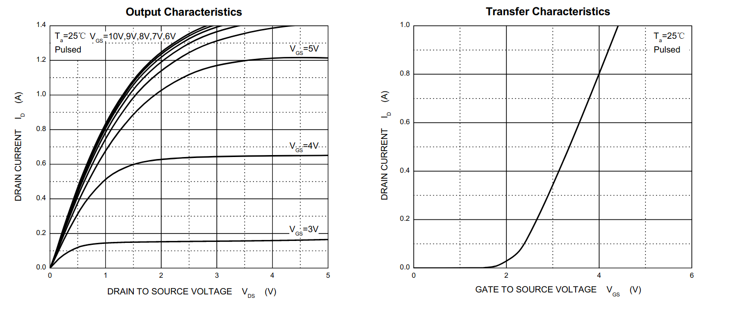
Above is an extract of the 2N7002 N-Channel FET datasheet. I want to use it as a load switch to drive the backlight of an LCD panel (Est 100mA). On the face of it this fits the bill with a stated Id of 115mA continuous drain current, but looking at the first graph above, with Vgs of 3.3v and Vds of 5v it looks like Id would be ~160mA. This would be OK pulsed, but my question is...
Do I need to place a current limiting resistor in series with the backlight to limit the maximum current to 115mA just in case I output a constant ranther than pulsed output, or should i just find a more capable FET?
Vance
Stephen Rodway
Jul 4, 2021, 3:56:00 AM7/4/21
to reading-...@googlegroups.com
Is the backlight a direct connection to the LEDs doing the backlighting,
or is it a 5V backlight with the limit resistors already built into the
unit?
Steve
> --
> You received this message because you are subscribed to the Google
> Groups "rLab / Reading's Hackspace" group.
> To unsubscribe from this group and stop receiving emails from it, send
> an email to reading-hacksp...@googlegroups.com
> <mailto:reading-hacksp...@googlegroups.com>.
> To view this discussion on the web, visit
> https://groups.google.com/d/msgid/reading-hackspace/CAFLXuqtPhiD1FRd9rDYfPhZ%3D7Oj-ybuP-9Nbj5i-Wo31wDHY2w%40mail.gmail.com
> <https://groups.google.com/d/msgid/reading-hackspace/CAFLXuqtPhiD1FRd9rDYfPhZ%3D7Oj-ybuP-9Nbj5i-Wo31wDHY2w%40mail.gmail.com?utm_medium=email&utm_source=footer>.
or is it a 5V backlight with the limit resistors already built into the
unit?
Steve
> You received this message because you are subscribed to the Google
> Groups "rLab / Reading's Hackspace" group.
> To unsubscribe from this group and stop receiving emails from it, send
> an email to reading-hacksp...@googlegroups.com
> <mailto:reading-hacksp...@googlegroups.com>.
> To view this discussion on the web, visit
> https://groups.google.com/d/msgid/reading-hackspace/CAFLXuqtPhiD1FRd9rDYfPhZ%3D7Oj-ybuP-9Nbj5i-Wo31wDHY2w%40mail.gmail.com
> <https://groups.google.com/d/msgid/reading-hackspace/CAFLXuqtPhiD1FRd9rDYfPhZ%3D7Oj-ybuP-9Nbj5i-Wo31wDHY2w%40mail.gmail.com?utm_medium=email&utm_source=footer>.

Richard Ibbotson
Jul 4, 2021, 4:00:07 AM7/4/21
to reading-...@googlegroups.com
From your description it suggests that you are driving the gate with 3.3V is that correct?
The 2N7002 will likely not switch on properly at 3.3v and I so dissipation will be high. I wouldn’t think suitable for more than 50mA.
I would find an MOSFET with a lower Vgs. Is surface mount OK?
Richard
--
You received this message because you are subscribed to the Google Groups "rLab / Reading's Hackspace" group.
To unsubscribe from this group and stop receiving emails from it, send an email to reading-hacksp...@googlegroups.com.
To view this discussion on the web, visit https://groups.google.com/d/msgid/reading-hackspace/CAFLXuqtPhiD1FRd9rDYfPhZ%3D7Oj-ybuP-9Nbj5i-Wo31wDHY2w%40mail.gmail.com.

Mark Robson
Jul 4, 2021, 4:02:11 AM7/4/21
to reading-...@googlegroups.com
I was wondering if that transistor seemed familiar, then I spotted in a schematic of mine,
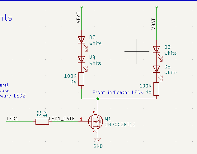
I drive LED1 with a ESP32 so it's a 3.3v logic signal. It seems to turn the leds on really brightly. VBAT is about 7v though.
I'm afraid I didn't consult the datasheet on RDS(on) I just used a mental model of the mosfet as a perfect switch :)
I guess it's not a problem if RDS(on) is 3 ohms if I've put it in series with a 100R.
Mark
PS: I have some of those mosfet left over from that project if you want to play with them. They are sot-23 package.
Vance Briggs
Jul 4, 2021, 4:05:34 AM7/4/21
to Reading Hackspace
Not sure, I picked up the LCD panel at the Sunday "Giveaway". I quickly tested the backlight by setting the current limiter on the PSU then applying 5V.
Vance
To unsubscribe from this group and stop receiving emails from it, send an email to reading-hacksp...@googlegroups.com.
To view this discussion on the web, visit https://groups.google.com/d/msgid/reading-hackspace/60E1698B.7050207%40legionelectronics.co.uk.
Vance Briggs
Jul 4, 2021, 4:07:16 AM7/4/21
to Reading Hackspace
Yes driving with 3.3v and surface mount is fine. I chose this as a starting point as it is one of JLPCB standard components for PCB Assembly...
Vance
To view this discussion on the web, visit https://groups.google.com/d/msgid/reading-hackspace/1C9DE7E7-BA1D-45E8-AA30-322ECB7793B2%40btinternet.com.
Vance Briggs
Jul 4, 2021, 4:17:19 AM7/4/21
to Reading Hackspace
Richard,
Looking at the datasheet using Vgs=3.3v and Vds=5V looks like we are very much in the saturation zone. I know you have a very broad electronics experience and I would like to know why you say it wouldn't turn on properly - Am I not neading the datasheet correctly?
Vance
To view this discussion on the web, visit https://groups.google.com/d/msgid/reading-hackspace/1C9DE7E7-BA1D-45E8-AA30-322ECB7793B2%40btinternet.com.
Richard Ibbotson
Jul 4, 2021, 4:34:20 AM7/4/21
to reading-...@googlegroups.com
Which graph are you referring to showing saturation ?
The Vgs threshold for the 2N7002 is around 2 volts where it starts to conduct and by a Vgs of around 4.5V it should be fully on with and Rds around 4 ohms. The region between will be resistive which impacts the current, voltage drop and heat dissipation.
Richard
On 4 Jul 2021, at 09:17, Vance Briggs <va...@axxe.co.uk> wrote:
To view this discussion on the web, visit https://groups.google.com/d/msgid/reading-hackspace/CAFLXuqt8Fnubq308eHJegZmvsV%3DE1n%2Bnt4ME8U0CpP5%2Bu2Dv9Q%40mail.gmail.com.
Richard Ibbotson
Jul 4, 2021, 4:43:29 AM7/4/21
to reading-...@googlegroups.com
To see how the MOSFET is performing you could measure the current by measuring the voltage across each resistor and then measure the voltage across the MOSFET.
The RDS(on) figure you quote is at 10V Vgs in the data sheet.
Does the MOSFET feel warm?
Richard
On 4 Jul 2021, at 09:13, Mark Robson <mar...@gmail.com> wrote:
I was wondering if that transistor seemed familiar, then I spotted in a schematic of mine,
<image.png>I drive LED1 with a ESP32 so it's a 3.3v logic signal. It seems to turn the leds on really brightly. VBAT is about 7v though.I'm afraid I didn't consult the datasheet on RDS(on) I just used a mental model of the mosfet as a perfect switch :)I guess it's not a problem if RDS(on) is 3 ohms if I've put it in series with a 100R.MarkPS: I have some of those mosfet left over from that project if you want to play with them. They are sot-23 package.
--
You received this message because you are subscribed to the Google Groups "rLab / Reading's Hackspace" group.
To unsubscribe from this group and stop receiving emails from it, send an email to reading-hacksp...@googlegroups.com.
To view this discussion on the web, visit https://groups.google.com/d/msgid/reading-hackspace/CAJ4NLMfxYCnyS7JtBtc0kfF6AJbvAXQ6etAwh5u9x_%2BH4dD72Q%40mail.gmail.com.
Vance Briggs
Jul 4, 2021, 4:45:12 AM7/4/21
to Reading Hackspace
I have marked where I think my operating point is on these graphs
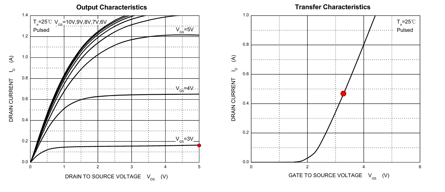
In the first graph we are well along the flat part of the Vgs=3V curve, which I am taking as saturation (maybe wrong). On the second graph there is no reference to Vds so I am not sure how to read that one - surely this is for some fixed value of Vds?
Vance
To view this discussion on the web, visit https://groups.google.com/d/msgid/reading-hackspace/1A839B32-31AE-402E-B62A-E5900A53FBF5%40btinternet.com.
Richard Ibbotson
Jul 4, 2021, 5:26:57 AM7/4/21
to reading-...@googlegroups.com
The graph is not showing saturation. The current goes up as Vgs increases.
While you are switching to a 5v supply your operating point is to minimise Vds when the MOSFET is switched on.
Richard
On 4 Jul 2021, at 09:45, Vance Briggs <va...@axxe.co.uk> wrote:
I have marked where I think my operating point is on these graphs
To view this discussion on the web, visit https://groups.google.com/d/msgid/reading-hackspace/CAFLXuqv%3DzggiFFKUMQhLMQeWbHOD1ht97AGxzCPqQieP1U8Sfg%40mail.gmail.com.
Richard Ibbotson
Jul 4, 2021, 5:42:42 AM7/4/21
to reading-...@googlegroups.com
Devices like this are specified for operation at low voltages. https://www.onsemi.com/pdf/datasheet/fdv301n-d.pdf
On 4 Jul 2021, at 10:26, Richard Ibbotson <richard....@btinternet.com> wrote:
The graph is not showing saturation. The current goes up as Vgs increases.
Vance Briggs
Jul 4, 2021, 7:14:51 AM7/4/21
to Reading Hackspace
So I am confusing Vds - I was taking this as supply voltage (which it would be if the FET was turned off), but it is actually measured voltage across the device itself and will therefore change depending on Vgs.
So, if you are happy to turn this into a learning point, the question then changes to "How do I choose an FET for switching from the datasheet? (Which parameters/graphs should I be looking at and what are the criteria?)"
Vance
To view this discussion on the web, visit https://groups.google.com/d/msgid/reading-hackspace/3E9625FE-B477-4E77-BEDF-FA462381904F%40btinternet.com.
Richard Ibbotson
Jul 4, 2021, 8:35:14 AM7/4/21
to reading-...@googlegroups.com
The first thing to look for is a MOSFET which has a specified performance at the best Vgs that you can achieve. This is not the Vgs threshold value but the lowest Vgs at which an Rds(on) is specified.
For the 2N7002 this is 5V so if working strictly to specification you rule it out.
The FDV301N has a max specified Rds(on) of 5 Ohms at 2.7 volts Vgs and an Id of 200 mA which should be suitable for you needs.
Devices like the AO3400 have even better performance and I think are on the JLC parts list.
Working any MOSFET in the unspecified Vgs range will not only have reduced performance but also be inconsistent between devices. This region is typically the so called linear region and used in low power amplifiers. However higher power switching MOSFETs are not designed to work in this linear region at all and may fail even when you think you are within power dissipation. This is due to the high power MOSFET being comprised of many smaller MOSFETs in parallel and too much dissipation for too long can cause a local burnout and a domino effect. This is also a factor if you do not switch the Gate voltage fast enough and spend too long in the linear region over time The MOSFET gates have quite high capacitance so drivers may be needed to give fast switching times at high PWM rates.
Richard
On 4 Jul 2021, at 12:14, Vance Briggs <va...@axxe.co.uk> wrote:
To view this discussion on the web, visit https://groups.google.com/d/msgid/reading-hackspace/CAFLXuqthKfCmFeSorYBFygcVjVBp8FRUfCunmrq4JZ0fHhZDOQ%40mail.gmail.com.
Reply all
Reply to author
Forward
0 new messages