On off 5v light diode switch x 30
57 views
Skip to first unread message

Richard / rgproduct
Jul 1, 2021, 4:23:51 AM7/1/21
to rLab / Reading's Hackspace
Hi All,
I hope you are well.
Was good to drop in last night a bump into a few people
Question
Am developing a non touch musical large scale Faberge egg
And want to use light diodes to trigger things.
Trouble is they do the opposite, open when lit and closed circuit when
Dark (or a hand causes a shadow) .
Is there a CC/OC version please or really simple way to hack the output.
Need 30 and space available is small so no arduino options please...
Thanks

Andy Noyes
Jul 1, 2021, 5:20:47 AM7/1/21
to rLab / Reading's Hackspace
Have you got a link to the switch you are using?
What is the output driving, just a logic input or switching something higher current?
Just a single transistor on the output of the switch may do the trick.
Richard / rgproduct
Jul 1, 2021, 5:33:55 AM7/1/21
to rLab / Reading's Hackspace
My reply failed!
Was looking at these
And just want to instantaneously trigger a 5v usb bank fed solenoid.
I don't mind what tech it uses as long as it is very simple and robust.
Looking to avoid sonic sensing etc.
Andy Noyes
Jul 1, 2021, 6:08:40 AM7/1/21
to rLab / Reading's Hackspace
If you want to send a pulse to the solenoid (rather than it being continually energised when the sensor is dark) then you will need a few other components as well. The most basic type of circuit for this is a 'one-shot monostable': https://en.wikipedia.org/wiki/Monostable_multivibrator
But spacewise, 30x of these you're probably better off connecting the sensors in an array (eg. 4 x 8 uses only 12 pins vs. 30) to an arduino and driving the outputs via a demultiplexing IC (74HC154 x2, 5 output pins on the arduino drives 32 outputs) You will also need transistors capable of driving the solenoids since the logic outputs won't supply enough current, and it's important to put a small diode across each solenoid coil (in the reverse direction to the normal current flow) to snub the inductive spikes from the coil, which the arduino won't like.
Richard / rgproduct
Jul 1, 2021, 6:17:40 AM7/1/21
to rLab / Reading's Hackspace
That's exactly what i want to avoid... No specific pulses needed.
Just a simple on and off and the user can define the on/off time
with their hand movement
Specifically don't want complex circuits.
A normally closed light dependent resistor/diode that can
pass 5v very low amperage. But they don't exist afaik.
Or, as you said earlier, a hack of a regular normally open diode resistor.
Simple and small...
Andy Noyes
Jul 1, 2021, 6:40:50 AM7/1/21
to rLab / Reading's Hackspace
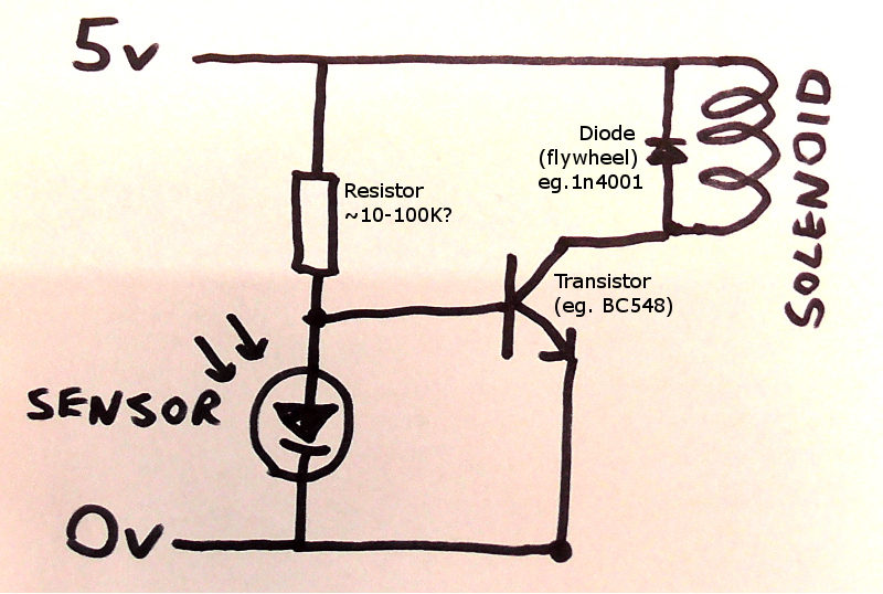
If only direct on/off control required that makes things easier. Below is a very simple circuit that will do this (could probably be improved). Others can probably advise on the component values, it depends largely on the resistance of the solenoid, best choose a transistor that can easily handle the current as in partial light it may be partially on and could get hot.
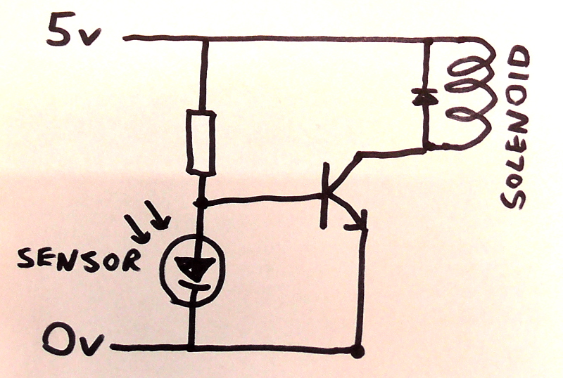 s easier
s easierRichard / rgproduct
Jul 1, 2021, 6:51:29 AM7/1/21
to rLab / Reading's Hackspace
Cool. Will measure the coil R later.
What is the other component?
Andy Noyes
Jul 1, 2021, 7:08:27 AM7/1/21
to rLab / Reading's Hackspace
Richard / rgproduct
Jul 1, 2021, 7:12:11 AM7/1/21
to rLab / Reading's Hackspace
Thanks! Will look into it...

Bob Dunlop
Jul 1, 2021, 7:26:02 AM7/1/21
to reading-...@googlegroups.com
Hi,
I don't know what a "5v usb bank fed solenoid" is ?
I'll assume it's a logic controlled solenoid, powered via a USB
connector but not controlled via same.
If the impedence is high enough (say a CMOS gate input) then there
could be some mileage in simply swapping the two component positions
in the PiHut description.
Resistor of 270K or more to the 5V supply, transistor to ground,
output is the junction between them. When dark the sensor draws
nano-amps and the output sees 5V via the resistor, when lit the
sensor should drag the output down to 0.3V by drawing ~20uA.
This is a high impedence circuit which I don't like, easily prey
to noise (electrical not audio) and even a potential for electro-
static damage. I'd ditch whatever the "usb bank" thing is and
go with a bare solenoid and a Darlington pair transistor to drive
it. You can get 8 pairs in a single package fairly easily, or a
single in a standard 3 lead transitor package. You'll still need
a protection diode if it's not already build into the solenoid as
is common with many relay coils these days. Just spotted some
Darlington packages include the protection diode ie ULN2003A #1.
Whatever you choose, breadboard a couple for testing first.
1: https://www.bristolwatch.com/ele/uln2003a.htm
On Thu, Jul 01 at 02:33, Richard / rgproduct wrote:
> My reply failed!
>
> Was looking at these
>
> https://thepihut.com/products/photo-transistor-light-sensor
>
> And just want to instantaneously trigger a 5v usb bank fed solenoid.
--
Bob Dunlop
I don't know what a "5v usb bank fed solenoid" is ?
I'll assume it's a logic controlled solenoid, powered via a USB
connector but not controlled via same.
If the impedence is high enough (say a CMOS gate input) then there
could be some mileage in simply swapping the two component positions
in the PiHut description.
Resistor of 270K or more to the 5V supply, transistor to ground,
output is the junction between them. When dark the sensor draws
nano-amps and the output sees 5V via the resistor, when lit the
sensor should drag the output down to 0.3V by drawing ~20uA.
This is a high impedence circuit which I don't like, easily prey
to noise (electrical not audio) and even a potential for electro-
static damage. I'd ditch whatever the "usb bank" thing is and
go with a bare solenoid and a Darlington pair transistor to drive
it. You can get 8 pairs in a single package fairly easily, or a
single in a standard 3 lead transitor package. You'll still need
a protection diode if it's not already build into the solenoid as
is common with many relay coils these days. Just spotted some
Darlington packages include the protection diode ie ULN2003A #1.
Whatever you choose, breadboard a couple for testing first.
1: https://www.bristolwatch.com/ele/uln2003a.htm
On Thu, Jul 01 at 02:33, Richard / rgproduct wrote:
> My reply failed!
>
> Was looking at these
>
> https://thepihut.com/products/photo-transistor-light-sensor
>
> And just want to instantaneously trigger a 5v usb bank fed solenoid.
Bob Dunlop
Richard / rgproduct
Jul 1, 2021, 8:04:37 AM7/1/21
to rLab / Reading's Hackspace
I have 40 odd low voltage solenoids, power in circuit supplied by 5v usb
Power bank.
Only a few will ever be activated at one time.
Richard / rgproduct
Jul 1, 2021, 10:03:08 AM7/1/21
to rLab / Reading's Hackspace
Solenoid measures at 35.7 ohms and seems to operate fine at 5v.
Just looking for a simple no touch way to trigger it instantaneously by
sweeping hands over sensor points, without any coding.
Cheers

Jeremy Poulter
Jul 1, 2021, 10:54:26 AM7/1/21
to rLab List
If you don't want to mess (too much) about with creating circuits, you could maybe put a relay in between the two, then you would have a choice of connecting the solenoid to either the NO or NC, a few of these for example https://www.amazon.co.uk/gp/product/B07QG2ZPZ2
Jeremy
--
You received this message because you are subscribed to the Google Groups "rLab / Reading's Hackspace" group.
To unsubscribe from this group and stop receiving emails from it, send an email to reading-hacksp...@googlegroups.com.
To view this discussion on the web, visit https://groups.google.com/d/msgid/reading-hackspace/7e56194e-1f5b-4b9e-9ca5-2eaf050666c6n%40googlegroups.com.
Richard / rgproduct
Jul 1, 2021, 11:17:59 AM7/1/21
to rLab / Reading's Hackspace
Thanks Jeremy,
Have No problem soldering together a little module (prefer that to
Arduino work) plus i really only want to string a 5v feed across my matrix
To keep wiring simple.
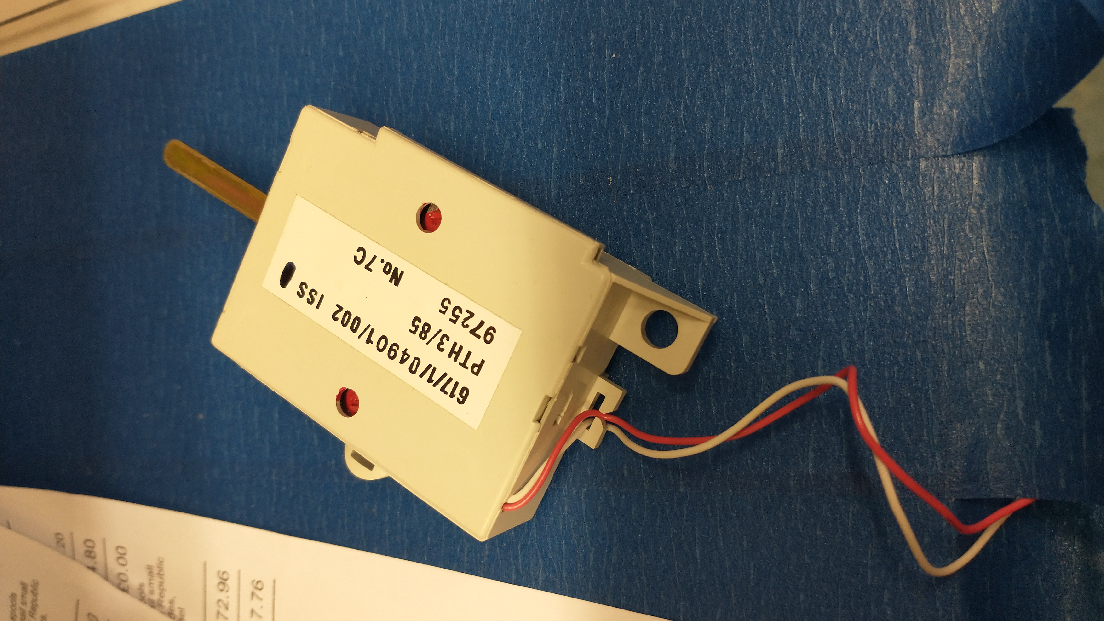
A bit like this image, sensors and relays in gold nodes and 5v power fed across network
My egg is 600mm tall and rings like a bell!
8dea is people can produce sound with not actually touching it.
Different nodes have different hammers and physical sound FX
So need to keep wiring, component size small as poss...
Via usb power  bank and solar top up
bank and solar top upRichard / rgproduct
Jul 1, 2021, 11:20:08 AM7/1/21
to rLab / Reading's Hackspace
So a simple circuit as above that converts and NO light diode to NC would be ideal.
I can then experiment with housing and shadow play/ R values
Reply all
Reply to author
Forward
0 new messages