Audio TRRS to TRRS crossover cable

Gavin

Richard Ibbotson
On 31 Dec 2021, at 11:35, Gavin <gavi...@gmail.com> wrote:
Hi. I have two devices, both with standard TRRS (stereo audio output + microphone input) sockets. They are both expecting a standard headset with microphone to be attached but I would like one to talk to the other via a cable.
Can I just take the two output channels from the output device and connect them (together) to the microphone channel on the receiving device? Or should I only use one channel? Are the input and outputs even at the right ‘level’?Gavin
--
You received this message because you are subscribed to the Google Groups "rLab / Reading's Hackspace" group.
To unsubscribe from this group and stop receiving emails from it, send an email to reading-hacksp...@googlegroups.com.
To view this discussion on the web, visit https://groups.google.com/d/msgid/reading-hackspace/CANjezMdF1TrStQw0YoCLnQwamqULnJgdGoOT3mQDHeakzxdJ_g%40mail.gmail.com.
Richard Ibbotson
On 31 Dec 2021, at 12:11, Richard Ibbotson <richard....@btinternet.com> wrote:
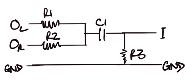
My thoughts are:
Gavin
To view this discussion on the web, visit https://groups.google.com/d/msgid/reading-hackspace/E5E39F81-7F35-41A9-BFEA-90B1BF8B1571%40btinternet.com.
Richard Ibbotson
Hi Gavin,
Yes, I would move the cap to the right to be on the on the path between I and R3. I would make R3 1K ohm to start and R1 and R2 to be around 22K ohm to start. Better if you have an oscilloscope to measure the voltages or just adjust value based on the level meters in the devices or distortion.
Cheers,
Richard
To view this discussion on the web, visit https://groups.google.com/d/msgid/reading-hackspace/EDDB49A6-6379-42F5-897B-68B2F207BC25%40gmail.com.
Gavin
Gavin

On 3 Jan 2022, at 01:32, Gavin <gavi...@gmail.com> wrote:Testing on an oscilloscope with the mic close to the tablet speaker, and the tablet making quite a loud noise, only gives a waveform with a range of 60mV either side of the bias voltage. Anyone know if this is about the right range?
Richard Ibbotson
Thanks Gavin,
Good to hear it is sounding out well for you.
I think you might also be gratified to hear that following your presentation to RADARC Reading Amateur Radio Club back a few years and plagues, that they are now using Kicad for several individual and club projects. Some of them are impedance-controlled RF designs on 4 layer boards mainly SMT.
Cheers,
Richard
From: reading-...@googlegroups.com <reading-...@googlegroups.com> On Behalf Of Gavin
Sent: Sunday, January 16, 2022 4:58 PM
To: reading-...@googlegroups.com
Subject: Re: [RDG-Hack] Audio TRRS to TRRS crossover cable
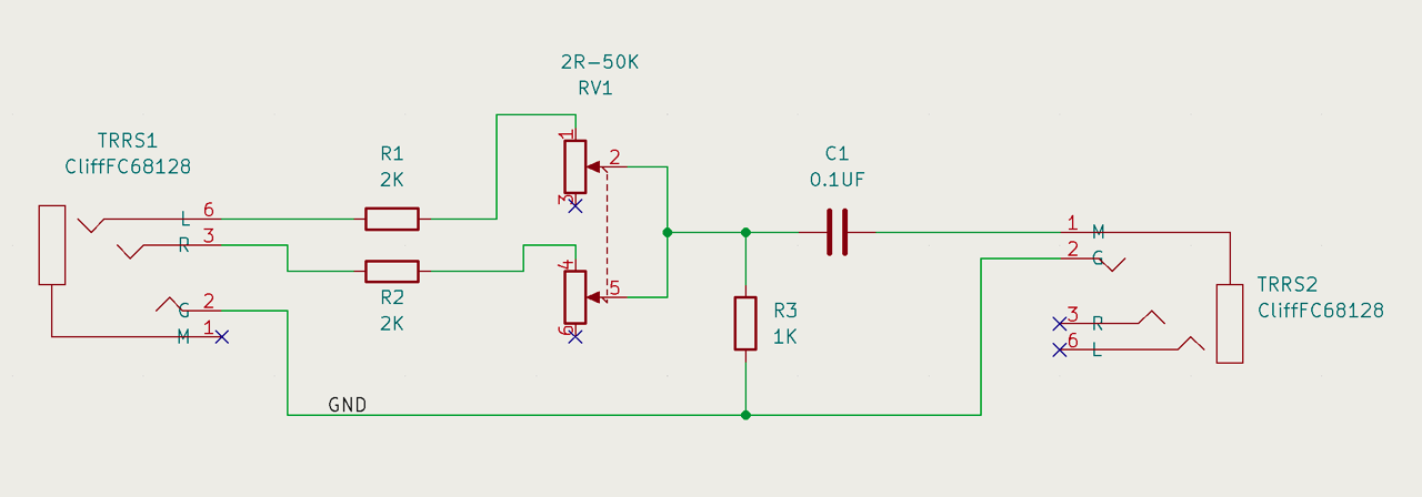
Principally out of thanks to Richard, but also for anyone else who might stumble across this post, I have made up the circuit in a breadboard and tested on both an oscilloscope and also with the actual target devices. The circuit as recommended by Richard works and I am going to have a board made up according to the following schematic (outputting device plugs into TRRS1 and the receiving device into TRRS2):
--
You received this message because you are subscribed to the Google Groups "rLab / Reading's Hackspace" group.
To unsubscribe from this group and stop receiving emails from it, send an email to reading-hacksp...@googlegroups.com.
To view this discussion on the web, visit https://groups.google.com/d/msgid/reading-hackspace/F6FBEF9F-4136-44D8-A10D-D356CB86C51C%40gmail.com.