RCZ80-PC project - ROMWBW not detecting RCWDC floppy controller
355 views
Skip to first unread message

Rodney Knaap
Oct 7, 2021, 11:47:22 AM10/7/21
to RC2014-Z80
Hello everyone,
First of all, I would like to say, I respect and appreciate all the work that has been done on ROMWBW and all it's code, my thanks to Wayne Warthen and all involved!
ROMWBW is actually providing many important solutions which enable many users to get many functions and structure out of their RC2014 hardware!
I am building my own version of the RC2014, and getting some experience with everything.
My goal will be to design an expanded RCZ80-PC, based on the latest ROMWBW code and several useful RC2014 interfaces.
So first I am testing all the separate interfaces, making sure that my schematics are working properly, and then I will merge them into a single schematic and design and build a RCZ80-PC mainboard PCB. Probably one which will fit in a PC case.
This PCB will also include several bus connectors for future testing and even further expansion of the PC system.
Having a single PCB with many features integrated will make it much easier to develop code for future expansions as well.
I plan to include some music synthesizers as well, which might interest chiptunes enthousiasts!
I will update my website with useful information about RC2014 interfaces for others which can aid the "getting started" experience.
I am eager to quickly solve any problems with my different interfaces so I can get them all done, and finally get to the actual work, designing the mainboard! Of course, I will gladly share my knowledge with anyone! As long as there are no objections of course!
I could use some help with my test efforts, and hope that some of the ROMWBW experts here can perhaps help to shed a light on my problem. I already read many other posts, but the information in those seems not relevant on my problem.
After just having built a PCB from the exact RC-WDC floppy interface schematic of Scott Baker separately for debugging purposes, I now can control a floppy drive with the FDU test program, so that's a good progress! I am using the LG(Goldstar) GM82C765B controller, which I verified in an old AT PC to work perfectly.
The problem I am still having now is that the WDC floppy controller is not showing up in the boot sequence of ROMWBW.
So, there is a detection problem that I have not been able to solve yet! I want to solve it, so I can use ROMWBW for booting and accessing the floppy drive for example in CP/M and Z-system.
I tried the default jumper settings and all 3 other combinations, and with the base address of 40h which results in the /FDC_CS signal to be triggered at port 50h which as I understand from info in the source directories is the default.
With everything at default, I still cannot get the floppy drive controller to be detected by ROMWBW.
I am using a custom ROMWBW ROM to test my hardware.
I cloned the latest dev source with git on my linux server.
Then copied the contents into my own folder (W10 PC)
I made a custom config and built the ROM from the relevant instructions, according to these settings:
RCZ80_mak.asm (in HBIOS/Config subdirectory)
-----------------------
#DEFINE BOOT_DEFAULT "H" ; DEFAULT BOOT LOADER CMD ON <CR> OR AUTO BOOT
;
#include "cfg_rcz80.asm"
;
CRTACT .SET FALSE ; ACTIVATE CRT (VDU,CVDU,PROPIO,ETC) AT STARTUP
;
CPUOSC .SET 7372800 ; CPU OSC FREQ IN MHZ
;
UARTENABLE .SET FALSE ; UART: ENABLE 8250/16550-LIKE SERIAL DRIVER (UART.ASM)
ACIAENABLE .SET TRUE ; ACIA: ENABLE MOTOROLA 6850 ACIA DRIVER (ACIA.ASM)
ACIA0BASE .SET $A0 ; ACIA 0: REGISTERS BASE ADR
SIOENABLE .SET FALSE ; SIO: ENABLE ZILOG SIO SERIAL DRIVER (SIO.ASM)
;
TMSENABLE .SET FALSE ; TMS: ENABLE TMS9918 VIDEO/KBD DRIVER (TMS.ASM)
TMSTIMENABLE .SET FALSE ; TMS: ENABLE TIMER INTERRUPTS (REQUIRES IM1)
TMSMODE .SET TMSMODE_RCV9958 ; TMS: DRIVER MODE: TMSMODE_[RC/RCV9958]
;
AY38910ENABLE .SET FALSE ; AY: AY-3-8910 / YM2149 SOUND DRIVER
;
FDENABLE .SET TRUE ; FD: ENABLE FLOPPY DISK DRIVER (FD.ASM)
FDMODE .SET FDMODE_RCWDC ; FD: DRIVER MODE: FDMODE_[DIO|ZETA|ZETA2|DIDE|N8|DIO3|RCSMC|RCWDC|DYNO|EPWDC]
FDMEDIA .SET FDM144 ; FDM720, FDM144, FDM360, FDM120 (ONLY RELEVANT IF FDENABLE = TRUE)
FDMEDIAALT .SET FDM720 ; ALTERNATE MEDIA TO TRY, SAME CHOICES AS ABOVE (ONLY RELEVANT IF FDMAUTO = TRUE)
FDMAUTO .SET TRUE ; SELECT BETWEEN MEDIA OPTS ABOVE AUTOMATICALLY
;
IDEENABLE .SET TRUE ; IDE: ENABLE IDE DISK DRIVER (IDE.ASM)
;
PPIDEENABLE .SET TRUE ; PPIDE: ENABLE PARALLEL PORT IDE DISK DRIVER (PPIDE.ASM)
;
PRPENABLE .SET FALSE ; PRP: ENABLE ECB PROPELLER IO BOARD DRIVER (PRP.ASM)
;
RP5RTCENABLE .SET FALSE ; RP5C01 RTC BASED CLOCK (RP5RTC.ASM)
;
MKYENABLE .SET FALSE ; MSX 5255 PPI KEYBOARD COMPATIBLE DRIVER (REQUIRES TMS VDA DRIVER)
-----------------------
With this custom ROM, below you can find my boot result.
If there are any comments, I would greatly appreciate it!
Ultimately my efforts will benefit the community!
Kind regards,
Rodney Knaap
My test logs:
----------------------
RomWBW HBIOS v3.1.1-pre.119, 2021-09-25
RC2014 Z80 @ 7.372MHz
0 MEM W/S, 1 I/O W/S, INT MODE 1, Z2 MMU
512KB ROM, 512KB RAM
ROM VERIFY: 00 00 00 00 PASS
ACIA0: IO=0xA0 ACIA MODE=115200,8,N,1
DSRTC: MODE=STD IO=0xC0 NOT PRESENT
MD: UNITS=2 ROMDISK=384KB RAMDISK=256KB
FD: MODE=RCWDC IO=0x50 NOT PRESENT
IDE: IO=0x10 MODE=RC
IDE0: NO MEDIA
IDE1: NO MEDIA
PPIDE: IO=0x20 PPI NOT PRESENT
Unit Device Type Capacity/Mode
---------- ---------- ---------------- --------------------
Char 0 ACIA0: RS-232 115200,8,N,1
Disk 0 MD0: RAM Disk 256KB,LBA
Disk 1 MD1: ROM Disk 384KB,LBA
Disk 2 IDE0: Hard Disk --
Disk 3 IDE1: Hard Disk --
A test with the excellent FDU test program results in this (shortened):
Floppy Disk Utility (FDU) v5.8, 26-Jul-2021 [HBIOS]
Copyright (C) 2021, Wayne Warthen, GNU GPL v3
SELECT FLOPPY DISK CONTROLLER:
(A) Disk IO ECB Board
(B) Disk IO 3 ECB Board
(C) Zeta SBC Onboard FDC
(D) Zeta 2 SBC Onboard FDC
(E) Dual IDE ECB Board
(F) N8 Onboard FDC
(G) RC2014 SMC (SMB)
(H) RC2014 WDC (SMB)
(I) SmallZ80 Expansion
(J) Dyno-Card FDC, D1030
(K) RC2014 EPFDC
(L) Multi-Board Computer FDC
(X) Exit
=== OPTION ===> RC-WDC
===== RC-WDC ==========<< FDU MAIN MENU >>======================
(S)ETUP: UNIT=00 MEDIA=720KB DS/DD MODE=POLL TRACE=00
----------------------------------------------------------------
(R)EAD (W)RITE (F)ORMAT (V)ERIFY
(I)NIT BUFFER (D)UMP BUFFER FDC (C)MDS E(X)IT
=== OPTION ===> SETUP
ENTER UNIT [00-03] (00): 00
00: 3.5" 720KB - 9 SECTORS, 2 SIDES, 80 TRACKS, DOUBLE DENSITY
01: 3.5" 1.44MB - 18 SECTORS, 2 SIDES, 80 TRACKS, HIGH DENSITY
02: 5.25" 320KB - 8 SECTORS, 2 SIDES, 40 TRACKS, DOUBLE DENSITY
03: 5.25" 360KB - 9 SECTORS, 2 SIDES, 40 TRACKS, DOUBLE DENSITY
04: 5.25" 1.2MB - 15 SECTORS, 2 SIDES, 80 TRACKS, HIGH DENSITY
05: 8" 1.11MB - 15 SECTORS, 2 SIDES, 77 TRACKS, DOUBLE DENSITY
06: 5.25" 160KB - 8 SECTORS, 1 SIDE, 40 TRACKS, DOUBLE DENSITY
07: 5.25" 180KB - 9 SECTORS, 1 SIDE, 40 TRACKS, DOUBLE DENSITY
08: 5.25" 320KB - 8 SECTORS, 1 SIDE, 80 TRACKS, DOUBLE DENSITY
09: 5.25" 360KB - 9 SECTORS, 1 SIDE, 80 TRACKS, DOUBLE DENSITY
ENTER MEDIA [00-09] (00): 01
00: POLLING (RECOMMENDED)
01: INTERRUPT (!!! READ MANUAL !!!)
02: FAST INTERRUPT (!!! READ MANUAL !!!)
03: INT/WAIT (!!! READ MANUAL !!!)
04: DRQ/WAIT (!!! NOT YET IMPLEMENTED!!!)
ENTER MODE [00-04] (00): 00
ENTER TRACE LEVEL [00-01] (00): 01
===== RC-WDC ==========<< FDU MAIN MENU >>======================
(S)ETUP: UNIT=00 MEDIA=1.44MB DS/HD MODE=POLL TRACE=01
----------------------------------------------------------------
(R)EAD (W)RITE (F)ORMAT (V)ERIFY
(I)NIT BUFFER (D)UMP BUFFER FDC (C)MDS E(X)IT
=== OPTION ===> READ (S)ECTOR, (T)RACK, (D)ISK, (R)ANDOM ===> RANDOM
RESET DRIVE...
SENSE INTERRUPT: 08 --> C0 00 [DISK CHANGE]
SENSE INTERRUPT: 08 --> C1 00 [DISK CHANGE]
SENSE INTERRUPT: 08 --> C2 00 [DISK CHANGE]
SENSE INTERRUPT: 08 --> C3 00 [DISK CHANGE]
SENSE INTERRUPT: 08 --> 80 [INVALID COMMAND]
SPECIFY: 03 D0 11 --> <EMPTY> [OK]
RECALIBRATE: 07 00 --> <EMPTY> [OK]
SENSE INTERRUPT: 08 --> 80 [INVALID COMMAND]
SENSE INTERRUPT: 08 --> 80 [INVALID COMMAND]
SENSE INTERRUPT: 08 --> 80 [INVALID COMMAND]
SENSE INTERRUPT: 08 --> 80 [INVALID COMMAND]
SENSE INTERRUPT: 08 --> 80 [INVALID COMMAND]
SENSE INTERRUPT: 08 --> 80 [INVALID COMMAND]
SENSE INTERRUPT: 08 --> 20 00 [OK]
PROGRESS: TRACK=02 HEAD=00 SECTOR=08
SEEK: 0F 00 02 --> <EMPTY> [OK]
SENSE INTERRUPT: 08 --> 20 02 [OK]
READ: 46 00 02 00 08 02 08 1B FF --> 40 80 00 02 00 08 02 [OK]
PROGRESS: TRACK=11 HEAD=01 SECTOR=07
SEEK: 0F 04 11 --> <EMPTY> [OK]
SENSE INTERRUPT: 08 --> 80 [INVALID COMMAND]
SENSE INTERRUPT: 08 --> 80 [INVALID COMMAND]
SENSE INTERRUPT: 08 --> 20 11 [OK]
READ: 46 04 11 01 07 02 07 1B FF --> 44 80 00 11 01 07 02 [OK]
PROGRESS: TRACK=0E HEAD=00 SECTOR=11
SEEK: 0F 00 0E --> <EMPTY> [OK]
SENSE INTERRUPT: 08 --> 20 0E [OK]
READ: 46 00 0E 00 11 02 11 1B FF --> 40 80 00 0E 00 11 02 [OK]
PROGRESS: TRACK=44 HEAD=01 SECTOR=12
SEEK: 0F 04 44 --> <EMPTY> [OK]
SENSE INTERRUPT: 08 --> 80 [INVALID COMMAND]
SENSE INTERRUPT: 08 --> 80 [INVALID COMMAND]
SENSE INTERRUPT: 08 --> 80 [INVALID COMMAND]
SENSE INTERRUPT: 08 --> 80 [INVALID COMMAND]
SENSE INTERRUPT: 08 --> 80 [INVALID COMMAND]
SENSE INTERRUPT: 08 --> 80 [INVALID COMMAND]
SENSE INTERRUPT: 08 --> 80 [INVALID COMMAND]
SENSE INTERRUPT: 08 --> 80 [INVALID COMMAND]
SENSE INTERRUPT: 08 --> 80 [INVALID COMMAND]
SENSE INTERRUPT: 08 --> 20 44 [OK]
READ: 46 04 44 01 12 02 12 1B FF --> 44 80 00 44 01 12 02 [OK]
PROGRESS: TRACK=25 HEAD=01 SECTOR=0E
SEEK: 0F 04 25 --> <EMPTY> [OK]

Wayne Warthen
Oct 7, 2021, 2:11:54 PM10/7/21
to RC2014-Z80
Hi Rodney,
It looks like you have a good handle on things. Your hardware is clearly working OK, so that is great.
It looks like there must be something odd going on with your build. With FDENABLE set to TRUE, you should see a line in the boot message that indicates the result of the FDC probe. For example, here is a line from one of my systems with FDENABLE set to TRUE, but no FDC installed.
FD: MODE=MBC IO=0x30 NOT PRESENT
Since there you have no FDC line at all, it implies the FD driver is not actually being included in the build.
If you want to post a copy of the hbios_rom.lst file from your build, I might be able to figure out what is going on.
Thanks,
Wayne
Rodney Knaap
Oct 7, 2021, 2:57:26 PM10/7/21
to RC2014-Z80
Hi Wayne,
Thanks for your reply!
I'm not sure I understood your explanation, but I am seeing a similar line as you described:
RomWBW HBIOS v3.1.1-pre.119, 2021-09-25
RC2014 Z80 @ 7.372MHz
0 MEM W/S, 1 I/O W/S, INT MODE 1, Z2 MMU
512KB ROM, 512KB RAM
ROM VERIFY: 00 00 00 00 PASS
ACIA0: IO=0xA0 ACIA MODE=115200,8,N,1
DSRTC: MODE=STD IO=0xC0 NOT PRESENT
MD: UNITS=2 ROMDISK=384KB RAMDISK=256KB
FD: MODE=RCWDC IO=0x50 NOT PRESENT
IDE: IO=0x10 MODE=RC
IDE0: NO MEDIA
IDE1: NO MEDIA
PPIDE: IO=0x20 PPI NOT PRESENT
I have attached the hbios_rom.lst from my build directory.
Thanks again for your help Wayne!
I would appreciate any advice!
Kind regards,
Rodney
Op donderdag 7 oktober 2021 om 20:11:54 UTC+2 schreef wwar...@gmail.com:
Wayne Warthen
Oct 7, 2021, 8:26:46 PM10/7/21
to RC2014-Z80
On Thursday, October 7, 2021 at 11:57:26 AM UTC-7 rodne...@gmail.com wrote:
Thanks for your reply!I'm not sure I understood your explanation, but I am seeing a similar line as you described:
I'm sorry Rodney. I was going too fast and missed the "FD:" line. So, that means you built it correctly. Let me double check that it is still working for me on the current dev code branch. I will try this now and post again.
-Wayne
Wayne Warthen
Oct 7, 2021, 9:17:06 PM10/7/21
to RC2014-Z80
OK, I tried my system with the current dev branch code, default build settings and there was no problem detecting the WDC controller.
Since you are already doing your own build, you could uncomment some debug statement in the fd.asm file to see if we can tell what is happening. If you want to do this, look at the fd.asm file. Find the FD_DETECT routine. Within this small routine, there are 4 lines that are commented out. Remove the semicolon in front of these statements. Build a new ROM and send me the boot messages.
Thanks,
Wayne
Rodney Knaap
Oct 8, 2021, 3:01:37 AM10/8/21
to RC2014-Z80
Hi Wayne,
Thanks for your reply and help with testing the dev code on your hardware!
I am sure this detect problem can be solved!
I have tested the new ROM with the debug lines uncommented, these are the boot messages:
RomWBW HBIOS v3.1.1-pre.119, 2021-10-08
RC2014 Z80 @ 7.372MHz
0 MEM W/S, 1 I/O W/S, INT MODE 1, Z2 MMU
512KB ROM, 512KB RAM
ROM VERIFY: 00 00 00 00 PASS
ACIA0: IO=0xA0 ACIA MODE=115200,8,N,1
DSRTC: MODE=STD IO=0xC0 NOT PRESENT
MD: UNITS=2 ROMDISK=384KB RAMDISK=256KB
FD: MODE=RCWDC IO=0x50 48 NOT PRESENT
IDE: IO=0x10 MODE=RC
IDE0: NO MEDIA
IDE1: NO MEDIA
PPIDE: IO=0x20 PPI NOT PRESENT
So it printed "48" in the boot message.
Thanks again for your advice Wayne!
Kind regards,
Rodney
Op vrijdag 8 oktober 2021 om 03:17:06 UTC+2 schreef wwar...@gmail.com:
Rodney Knaap
Oct 8, 2021, 4:36:28 AM10/8/21
to RC2014-Z80
Hi Wayne,
Sorry, I have been too hasty to send you the result, in further testing I have found the debugging byte kept changing!
I replaced the 74HC125 by a 74LS125, I couldn't find any other 74HC125 ICs in my parts.
After that, I found a consistant debugging byte of 80!
And also, resulting from this, a successful detection of the FDC by the ROMWBW boot messages!
Below I included the correct boot messages.
I was using a longer floppy drive flatcable which supports two drives, I found when actually plugging in two floppy drives, that made the communication from the FDC chip to the drives much more stable without any loose cable ends. The floppy drives seem to terminate the flatcables to keep the signals on the floppy bus clean!
So it's looking really great because I can use the floppy drives with ROMWBW!
So far, I have used FDU to format a disk, and used ZSDOS to CLRDIR the directory.
After that, the directory correctly reported as empty from a DIR command.
I have copied the contents of B: to the floppy disk C: with zero errors.
After the copy, the directory of C: is correctly shown.
I have run some commands from floppy drive C: also without errors.
After these tests, everything looks in order!
Thanks again for your time, Wayne!
To see the debugging info was the key for solving this problem, which looks like some IC timing issue, or a defective IC!
I will quickly continue my work to build and verify all the RC2014 interfaces which I want to merge into my RCZ80-PC.
Still much to be done!
As soon as all drive controllers are done, I will update my web page:
Kind regards,
Rodney
--------------------------------------
RomWBW HBIOS v3.1.1-pre.119, 2021-10-08
RC2014 Z80 @ 7.372MHz
0 MEM W/S, 1 I/O W/S, INT MODE 1, Z2 MMU
512KB ROM, 512KB RAM
ROM VERIFY: 00 00 00 00 PASS
ACIA0: IO=0xA0 ACIA MODE=115200,8,N,1
DSRTC: MODE=STD IO=0xC0 NOT PRESENT
MD: UNITS=2 ROMDISK=384KB RAMDISK=256KB
RC2014 Z80 @ 7.372MHz
0 MEM W/S, 1 I/O W/S, INT MODE 1, Z2 MMU
512KB ROM, 512KB RAM
ROM VERIFY: 00 00 00 00 PASS
ACIA0: IO=0xA0 ACIA MODE=115200,8,N,1
DSRTC: MODE=STD IO=0xC0 NOT PRESENT
MD: UNITS=2 ROMDISK=384KB RAMDISK=256KB
FD: MODE=RCWDC IO=0x50 80 80 UNITS=2
IDE: IO=0x10 MODE=RC
IDE0: NO MEDIA
IDE1: NO MEDIA
PPIDE: IO=0x20 PPI NOT PRESENT
Unit Device Type Capacity/Mode
---------- ---------- ---------------- --------------------
Char 0 ACIA0: RS-232 115200,8,N,1
Disk 0 MD0: RAM Disk 256KB,LBA
Disk 1 MD1: ROM Disk 384KB,LBA
---------- ---------- ---------------- --------------------
Char 0 ACIA0: RS-232 115200,8,N,1
Disk 0 MD0: RAM Disk 256KB,LBA
Disk 1 MD1: ROM Disk 384KB,LBA
Disk 2 FD0: Floppy Disk 3.5",DS/HD,CHS
Disk 3 FD1: Floppy Disk 3.5",DS/HD,CHS
Disk 4 IDE0: Hard Disk --
Disk 5 IDE1: Hard Disk --
Disk 3 FD1: Floppy Disk 3.5",DS/HD,CHS
Disk 4 IDE0: Hard Disk --
Disk 5 IDE1: Hard Disk --
--------------------------------------
Op vrijdag 8 oktober 2021 om 09:01:37 UTC+2 schreef Rodney Knaap:
Wayne Warthen
Oct 8, 2021, 11:29:25 AM10/8/21
to RC2014-Z80
Interesting. I'm glad you got it working, but I have no idea why swapping the '125 fixed it. The interface was obviously working under the FDU tool. The debug byte value of 0x48 is a rational value for the FDC Master Status Register, but it indicates that the chip is still executing a command. That makes no sense since the FDC was just issued a reset. I confirmed that there is a good conservative delay after issuing the reset to the FDC chip.
Anyway, I may just need to call this a win without really ever knowing exactly what was happening.
Your website is good. I didn't realize you were hand building the boards. Nice work.
Thanks,
Wayne

Mark T
Oct 8, 2021, 12:00:09 PM10/8/21
to RC2014-Z80
Maybe try with a 74HCT125 instead. It could be that the inputs are not high enough to register as logic 1 on a 74HC125.
Another possibility is to add pull up resistors on the 74HC125 inputs.
Rodney Knaap
Oct 9, 2021, 12:10:15 PM10/9/21
to RC2014-Z80
Hi Wayne,
Thanks again for your explanation! It seems I am missing something. It is indeed strange!
When I was testing, I saw different debugging bytes, all not 80, which was explaining the failure to detect.
Maybe there is another coincidence happening.
If I find anything else by testing, I will reply to this thread if it can clarify the problem!
Thanks Mark for your suggestion! I have had some situations before where it was rather critical to use HC or HCT types before!
I will keep it in mind! I need to get more parts for testing.
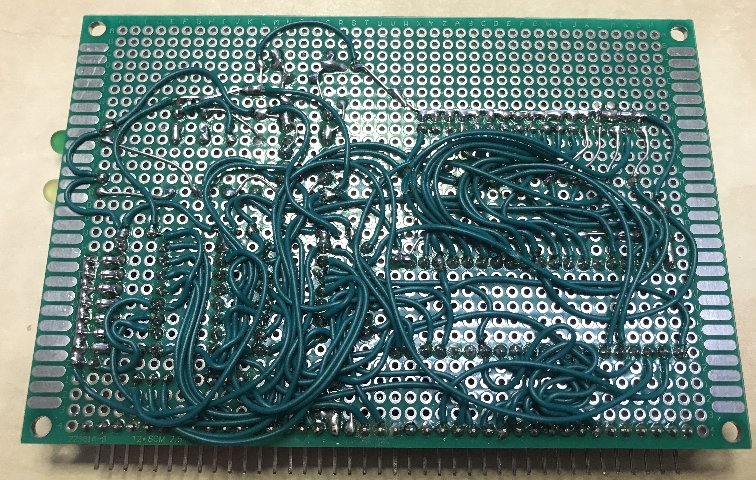
Yes, I am manually wiring in those PCBs from the PCB program which I use to know where the connections need to go.
After that I verify by checking all connections with the netlist file. Those PCBs are really for testing only.
It's a little laborious, but not too bad! Below you can see the FDC.
I desoldered that Goldstar controller from my old AT PC and soldered an IC socket into that ISA adapter card for testing in the PC.
I also have some new LGS controllers, which I verified in the PC.
It's great to now have a verified floppy drive interface to include in my RCZ80-PC mainboard design!
I am now working on a separate PPIDE PCB, again just to verify it. It's almost finished.
I changed the I/O decoder from some diode-resistor logic to normal gates.
I want to get some experience with this PCB and how to setup a harddisk etc., I have read some manuals which were included in the ROMWBW source directories.
There is much to explore and test still!
Thanks again,
kind regards,
Rodney

Op vrijdag 8 oktober 2021 om 18:00:09 UTC+2 schreef Mark T:
Wayne Warthen
Oct 9, 2021, 5:07:06 PM10/9/21
to RC2014-Z80
Very nice work on the point-to-point wiring. I'm impressed. Not something I have the patience for. 🙂
Indeed, if you do pin down the exact cause of the unexpected FDC MSR values, let me know.
Thanks,
Wayne
Reply all
Reply to author
Forward
0 new messages