A simpler '14
1,321 views
Skip to first unread message

Steve Cousins
Sep 13, 2018, 1:40:39 PM9/13/18
to RC2014-Z80
Hi all
I've observed that the RC2014 system is getting more sophisticated, with more exotic modules being produced by Spencer and also by the community.
I'm also conscious of the problems new users have with the quantity of soldering required, the configuration jumpers, memory paging and so on. Then if it doesn't work they are faced with a relatively complex multi-board system to fault find, with no working system for comparison and no spare modules to swap out. Nightmare!
I suspect quite a few never get their systems working and even more are put off from getting into the '14 universe by the apparent complexity and scale of the build. What a shame!
So I got thinking. How to make entry into this universe easier and more reliable?
Here's what I've come up with so far.

I've addressed the above mentioned problem areas by essentially designing a simpler '14. Simpler, meaning less components, less soldering, less configuration jumpers, less circuit boards.
I have produced a pretty minimal, but still expandable, RC2014 system. It can work in a modest way as a single board computer (SBC), yet can easily be expanded to run CP/M and more.
Actually this design is very similar to my SC101 prototype from last year.
Here's the specs:
Z80 running at 7.3728 MHz
128k bytes RAM (second 64k not easy to use, so best consider it to be 64k usable)
32k bytes ROM, which can be paged out with the usual write to port 0x38
Simple bit-bang serial port to get you started
Four RC2014 standard bus sockets
Simple reset button (no power on reset or reset debounce)
LED for power and status indication
Runs the Small Computer Monitor, with ROM BASIC and the CP/M loader included
It will have comprehensive documentation
The idea is that you can build the board without even fitting those tedious RC2014 sockets, then test it with the simple bit-bang serial port. This only involves assembling the components shown in the close up photo. That's 5 chips + oscillator + 6 pin header + a few Rs and Cs + LED + reset button. Looks like this takes about 175 solder joints. Sounds a lot, but way fewer than typical RC2014. Should be a good chance of such a simple circuit working first time. If it doesn't work then it is a relatively simple circuit to troubleshoot. The onboard LED can flash results of the self test, so a serial port problem will not look like a dead processor. You can then add the four 40 pin RC2014 module sockets. So that's a further 160 solder joints, but it is incremental assembly thus relatively easy to work out where any new fault is.
The next step would be to build and test a proper serial port, such as the official Z80 SIO module. Other modules are also available. Then if you want CP/M all you need to add is the official Compact Flash module and a Compact Flash card with the standard CP/M distribution installed. All this is supported by the ROM with no configuration required.
You can even add backplanes from the modular backplane range, although their functionality is limited by the single row standard 40 pin expansion socket on the motherboard. Hm, now wondering if the backplane expansion socket should be the fully featured 80 pin socket.
The motherboard has relatively few comonents and is thus quite a cheap build, so if it does not prove expandable enough it is not a big deal to discard it, take the useful modules and move to a Pro system.
I think this approach could attract more people to the RC2014, but to make it attractive to many it would probably have to be available as a complete kit. Not sure if I want to get into that.
Comments appreciated.
Steve

karlab
Sep 13, 2018, 2:50:38 PM9/13/18
to RC2014-Z80
Hi Steve
Very nice, I think you have made a well designed and affordable system for beginners.
I think you are right about many beginners; they build their kit, it doesn't work and they leave the community and that's a shame.
I don't think the number of soldering points/joints is the main problem for beginners.
I think it's much more important to have good spacing between components and having the PCB properly labeled, making it easier to troubleshoot.
Because all beginners will do soldering errors. It's how to correct these errors that matter.
I have one comment to your design, I would like to see a MC68B50 ACIA incorporated, just to get a speedier connection.
Karl

Mark T
Sep 13, 2018, 2:51:49 PM9/13/18
to RC2014-Z80
Hi Steve,
Serial interface is interesting way to avoid the 6850, especially the input of RXD to D7 with only a resistor for any uncommitted address port. Is it tested with 10K or just a starting point?
Curious why you chose to use A3-A5 for the address to the 74HCT259 as that seems to block quite a large spread of addresses.
Would it be able to support the 32K ram chip for Basic only?
If you had a spare OR or NOR gate available you might generate A16 for the RAM from A15 + PAGE, then high 32K is fixed but low 32K can be swapped. I was considering this for an earlier version of my single board z80 but decided on the 512K when I figured out a paging scheme with a single chip.
Might be better to use resistors to pull up /NMI, /BUSRQ and /WAIT, so for experimenting you don't need to cut traces.
Undecided about the 40 pin v. 80 pin or enhanced connectors. I prefer the stability of the 80 pin connectors, but as the purpose is to make assembly as easy and reliable as possible it might be best to stick with 40 pin connectors. Two rows of pins to solder so close together is probably a big risk for novice solderers. Maybe a compromise would be 3 x 40 pin connectors and one 80 pin full bus for expansion to a modular backplane.
I think you are probably right about the need for a complete kit to make it available to novices, at least a simple source for a programmed rom with the board.
Mark

brwella...@gmail.com
Sep 13, 2018, 2:57:36 PM9/13/18
to RC2014-Z80
Hi Steve,
One of my first goes at building a simple setup to minimise the soldering etc. was to use a RC2014 Mini with a Backplane 5 joined on the expansion port.. Left off the Pi Zero adapter and had basically what you are proposing but you have essentially married the two sections onto a single board to form the basic SBC.
It is appreciated that the Mini only has 32k RAM on board which needs to be removed when upgrading the system to 64K.
To get CPM etc. I just removed both the Mini's ROM and RAM IC's and used a standard 512k RAM/ 512K ROM module to run RomWBW.
The one main advantage your proposal has is it retains all the initial bits when upgrading for CPM as it only needs the addition of a Compact Flash module to get CPM without the use of the rather expensive RomWBW module!
I am sure that a kit of this kind will help encourage many new users to get involved in this hobby especially as getting several of the configuration links correct was one of my main hurdles to overcome in order to get the thing to actually do something!
Will look forward to your seeing any future developments on this topic.
Brian
Steve Cousins
Sep 13, 2018, 4:10:41 PM9/13/18
to RC2014-Z80
Thanks Karl
I have labelled pins on the bottom of the board to help with fault finding.

I don't share your experience of the Z80 SIO being slow compared to the 68B50.
With SCMonitor on the LiNC80 SBC you can software select baud rates up to 230k and it works fine. You can even download hex files flat out without handshaking at 230k baud.
... or do you run your 68B50 at a baud rate higher than 230k?
Oh, just figured you are probably having problems as I believe you run your processor at 20 MHz. The highest spec SIO I remember seeing is rated at only 10 MHz.
Is that what you were referring to?
If so it is not really relevant to this starter design as I would not be looking to support different clock speeds.
Actually, you could plug in a 68B50 module instead of the Z80 SIO module. SCM supports it and there is a version of CP/M for it.
Steve

Bill Shen
Sep 13, 2018, 4:12:02 PM9/13/18
to RC2014-Z80
Hi Steve,
Very cool! I'm working on two designs with very similar ideas:
1. Motherboard based on ZZ80RC. Since ZZ80RC is only 50mm x 100mm, the remaining space is idea for 3 connectors for RC2014 modules plus one horizontal connector (like yours) for backplane expansion. My goal is to use that as a platform to do multiprocessing, it also give me more motherboards so I don't have to plug/unplug modules from my one official 5-slot backplane.
2. Add address decode logic to ZZ80RC so it becomes an affordable "diagnostic module". It will be able to access as well as program RC2014 RAM/ROM module. Change the jumpers, it can boot off the RC2014 RAM/ROM module. It can also access & test the various I/O modules. The fact the ZZ80RC is ROM-less means we can distribute new/updated diagnostic software and try it out. I thought about building up a few such modules and "loan" them out to people who have problems bringing up RC2014 modules. The boards are cheap enough that I don't care to have them back, so the diagnostic modules can be loan out to next people who are having problems and so on.
Bill
karlab
Sep 13, 2018, 4:24:46 PM9/13/18
to RC2014-Z80
The labeling is brilliant.

I was referring the serial header on the motherboard.
With the motherboard as a self-contained kit, I think 9600 baud is a bit slow.
But adding a serial module as shown in one of your pictures enables higher communication speed.
regarding my own setup I run the 68B50 at 115k baud.
karl
Steve Cousins
Sep 13, 2018, 4:40:58 PM9/13/18
to RC2014-Z80
Hi Mark, see below
On Thursday, 13 September 2018 19:51:49 UTC+1, Mark T wrote:
Hi Steve,Serial interface is interesting way to avoid the 6850, especially the input of RXD to D7 with only a resistor for any uncommitted address port. Is it tested with 10K or just a starting point?
I have not got as far as writing the bit-bang code yet, so not sure about the 10K resistor. However, I did have working serial on my very similar, SC101 prototype a while back. I'm not sure this port will work on a significantly expanded system though due to extra loading. Or perhaps the rest of the expanded system will fail due to the resistor.
BUT. The idea is you don't need the on-board serial port once you have a proper serial module working. Then the on-board port could be used for messing about, or as a few simple I/O lines, or just ignored. If ignored, the resistor does not have a connection so will not load the bus and the I/O addresses used for the output are freed up for other modules.
Curious why you chose to use A3-A5 for the address to the 74HCT259 as that seems to block quite a large spread of addresses.
That decision was all about only using two 74 series chips for all the logic. The design requires A2 to be low (see OR gate) so it works out that each output function occupies 4 addresses, not the 8 it might appear at first glance. True they are spread out, but only use half that block. I did it that way round so I could have the paging function at the usual address of 0x38, thus keeping software compatibility.
Would it be able to support the 32K ram chip for Basic only?
I guess a small modification to the design would allow this, but I've not considered it as I want this design to easily upgraded to CP/M, which requires 64K. There is so little difference in cost between the chips I really don't think it is worth doing another version just to run BASIC only. This version could have a BASIC only ROM if required.
If you had a spare OR or NOR gate available you might generate A16 for the RAM from A15 + PAGE, then high 32K is fixed but low 32K can be swapped. I was considering this for an earlier version of my single board z80 but decided on the 512K when I figured out a paging scheme with a single chip.
No spare gates I'm afraid... unless you can design a version with only two 74 series chips to do the job. I am keen to keep the component count down to a minimum.
Might be better to use resistors to pull up /NMI, /BUSRQ and /WAIT, so for experimenting you don't need to cut traces.
I considered that, along with using 80 pin bus connectors, but in the end I stuck to my goal of a minimal system. Avoiding spec drift requires discipline.
Undecided about the 40 pin v. 80 pin or enhanced connectors. I prefer the stability of the 80 pin connectors, but as the purpose is to make assembly as easy and reliable as possible it might be best to stick with 40 pin connectors. Two rows of pins to solder so close together is probably a big risk for novice solderers. Maybe a compromise would be 3 x 40 pin connectors and one 80 pin full bus for expansion to a modular backplane.
Yes, I agree with all that.
Steve Cousins
Sep 13, 2018, 4:43:04 PM9/13/18
to RC2014-Z80
Thanks Brian, appreciate your comments.

Alan Cox
Sep 13, 2018, 4:49:59 PM9/13/18
to rc201...@googlegroups.com
I think there are two related problems. At least the ones I had
1. It's not obvious for most of the hardware how to assemble it bit by bit and test it. Some of the S100 CPU cards have excellent documentation where you add some bits, check things, add more and so on. They do assume you've got tools however. For RC2014 being able to build cards one by one helps but really you need a way to swap them about at the moment.
2. There isn't an easy way to get a single part running and tick it off, then the next and so on.
I was wondering whether it would actually make sense to figure out how to wire a totally off the shelf 5v arduino up a backplane so it could be set up to check all the lines for cross connections, then do I/O and memory accesses to the card albeit not at 7.3Mhz, so you would be able to test anything but the CPU card with nothing but an Arduino plugged onto an adapter card.
On retrobrew Will was playing with a similar setup where the 'I/O' is something like an Arduino which is what prompted those thoughts.
For me the biggest problem with this stuff though is that it's got elements of 'if you want to get there I wouldn't have started from here'. A 68HC11 is much better as a novice build project because you don't need a lot to get it up and chatting, and can then add and debug external hardware. Of course it speaks motorola not 8080 bus 8(
For your 128K it can certainly be used as a ramdisc providing you can toggle the ROM in and out and the ROM at minimum has a routine to ldir between banks. For CP/M 3 you need some true shared space even 32K/32K split and lose 32K of RAM by doing A16 = banksel or A15, or similar for 16/48K. I've been playing with the straight 64K switch via ROM. It's a bit of PITA but certainly works for a ramdisk (yes my rc2014 emulator has a mode for your board ;))
I loathe bitbang serial but for this use case I think it's a great idea and CP/M in the early days ran on machines with bitbang serial.
Steve Cousins
Sep 13, 2018, 4:51:15 PM9/13/18
to RC2014-Z80
Hi Bill
Your stuff is great. I really like the ROMless design.
Just got to say this :)
I'll have to patent the three vertical sockets and one horizontal socket design to stop similar looking products. If mobile phone makers can argue that a rectangle with rounded corners should be unique to them, I should have no problems in court!
The idea of passing round your kit as a diagnostic tool is very generous. I'm sure it will help a lot of unfortunate builders who run into problems.
Steve
Alan Cox
Sep 13, 2018, 4:57:18 PM9/13/18
to rc201...@googlegroups.com
>> If you had a spare OR or NOR gate available you might generate A16 for the RAM from A15 + PAGE, then high 32K is fixed but low 32K can be swapped. I was considering this for an earlier version of my single board z80 but decided on the 512K when I figured out a paging scheme with a single chip.
>
> No spare gates I'm afraid... unless you can design a version with only two 74 series chips to do the job. I am keen to keep the component count down to a minimum.
Is a pair of diodes cheating ?
>
> No spare gates I'm afraid... unless you can design a version with only two 74 series chips to do the job. I am keen to keep the component count down to a minimum.
Alan
Bill Shen
Sep 13, 2018, 5:07:07 PM9/13/18
to RC2014-Z80
I, ahem, pinched the idea from Spencer when I received his official 5-connector backplane and found an extra right-angle 40-pin socket. Staring at it a bit, I realized it meant to be mounted at the end of the backplane so I can plug a board horizontally or another backplane into it.
Passing Z280-based SBC around also have the added benefits of getting people to know about Z280. It is a very interesting CPU I hope more people will start developing hardware & software for it.
Bill
Passing Z280-based SBC around also have the added benefits of getting people to know about Z280. It is a very interesting CPU I hope more people will start developing hardware & software for it.
Bill
Alan Cox
Sep 13, 2018, 5:25:38 PM9/13/18
to rc201...@googlegroups.com
I take the diodes back. I think you have enough gates if you are
prepared to make use of the Z80 high address line I/O behaviour and
are prepared to do Sinclair grade hacks 8)
Instead of taking A2-A0 into U4.1 take A15,A14,and RAMA16 into it and
then also feed it to the real A16. It's slightly quirky in that you
now can't switch the ROM in and out from one of the RAM bank settings
but it moves the port up high so with sensible code you can access all
the RC2014 bus I/O card space.
In fact you could probably simplify it all and possibly lose an IC
with an Amstrad like approach where you just use A15, A14, ... as
enables and always do 16bit I/O. Not enabling anything on the low bits
leaves you with zero clashes although you have to use IN A,(C) and
friends. it's how the Amstrad CPC systems were done and some of the
later spectrums also did bits of it. Instead of assuming the Z80 has
8bits of I/O and 8bits of weird, you assume the Z80 has 8 chip select
lines and 8 I/O addresses per select 8). Offboard I/O is 00xx and
that's the same range as Z280 can hit and everyone is so far using.
It does make the software a bit harder but the builder isn't fighting
the software but the hardware. The software is in a PROM and assumed
to be right.
Alan
> --
> You received this message because you are subscribed to the Google Groups "RC2014-Z80" group.
> To unsubscribe from this group and stop receiving emails from it, send an email to rc2014-z80+...@googlegroups.com.
> To post to this group, send email to rc201...@googlegroups.com.
> To view this discussion on the web, visit https://groups.google.com/d/msgid/rc2014-z80/10bb0980-e555-4fdd-b13c-980ae62849ba%40googlegroups.com.
> For more options, visit https://groups.google.com/d/optout.
prepared to make use of the Z80 high address line I/O behaviour and
are prepared to do Sinclair grade hacks 8)
Instead of taking A2-A0 into U4.1 take A15,A14,and RAMA16 into it and
then also feed it to the real A16. It's slightly quirky in that you
now can't switch the ROM in and out from one of the RAM bank settings
but it moves the port up high so with sensible code you can access all
the RC2014 bus I/O card space.
In fact you could probably simplify it all and possibly lose an IC
with an Amstrad like approach where you just use A15, A14, ... as
enables and always do 16bit I/O. Not enabling anything on the low bits
leaves you with zero clashes although you have to use IN A,(C) and
friends. it's how the Amstrad CPC systems were done and some of the
later spectrums also did bits of it. Instead of assuming the Z80 has
8bits of I/O and 8bits of weird, you assume the Z80 has 8 chip select
lines and 8 I/O addresses per select 8). Offboard I/O is 00xx and
that's the same range as Z280 can hit and everyone is so far using.
It does make the software a bit harder but the builder isn't fighting
the software but the hardware. The software is in a PROM and assumed
to be right.
Alan
> You received this message because you are subscribed to the Google Groups "RC2014-Z80" group.
> To unsubscribe from this group and stop receiving emails from it, send an email to rc2014-z80+...@googlegroups.com.
> To post to this group, send email to rc201...@googlegroups.com.
> To view this discussion on the web, visit https://groups.google.com/d/msgid/rc2014-z80/10bb0980-e555-4fdd-b13c-980ae62849ba%40googlegroups.com.
> For more options, visit https://groups.google.com/d/optout.
Steve Cousins
Sep 13, 2018, 5:33:26 PM9/13/18
to RC2014-Z80
Hi Alan, thanks for your comments.
Good documentation is part of the plan for this project. I'm thinking this is a design for those with less experience than most RC2014 owners, so documentation will be particularly important.
I agree the increment build idea is rather restricted here. But every little helps.
The Arduino is a good idea does have the potential to provide a valuable diagnostic tool. Quite similar to Bill's ideas actually. When will it be ready :)
The Z80 does indeed require more supporting components than some processors, but it isn't a bad place to start from.
As for the second 64k of RAM, I agree a RAM disk is not too difficult. With a bit of effort it could even house some code, but deminishing returns on effort would probably be the limiting factor in the end.
Bit-banging serial, I2C, SPI is what minimal systems should spend all their time doing. Minimal is good. But seriously, I agree the limitations of bit-banging can be a real handicap.
Steve
Alan Cox
Sep 13, 2018, 5:39:11 PM9/13/18
to rc201...@googlegroups.com
> Bit-banging serial, I2C, SPI is what minimal systems should spend all their time doing. Minimal is good. But seriously, I agree the limitations of bit-banging can be a real handicap.
Good point - and from a CP/M perspective if you have a few bit bang
bits you can do SPI and thus SD card at a slow but usable speed, so it
would avoid the need for any external card to do CP/M 2.2.
Alan
Steve Cousins
Sep 13, 2018, 5:47:50 PM9/13/18
to RC2014-Z80
Hi Alan
Some great ideas there thanks.
I'll give it a bit of thought. Dropping another IC would be very attractive.
One possible fly in the ointment though is the desire to keep the hardware compatible with existing software. As it stands the key compatibility requirement is the memory paging via I/O port address 0x38. While I am happy to write what is needed in the ROM, I would really like it to run the standard RC2014 CP/M distribution. Within this distribution's BIOS code there are a couple of writes to 0x38 for page selection. I'd have to study the code to see if this would be an issue. Also it would be nice if the hardware could run other standard RC2014 ROM software. Creating non-compatible hardware causes fragmentation of the ecosystem so I'd like to avoid it if possible.
Steve
> To unsubscribe from this group and stop receiving emails from it, send an email to rc2014-z80+unsubscribe@googlegroups.com.
Alan Cox
Sep 13, 2018, 6:36:52 PM9/13/18
to rc201...@googlegroups.com
> One possible fly in the ointment though is the desire to keep the hardware compatible with existing software. As it stands the key compatibility requirement is the memory paging via I/O port address 0x38. While I am happy to write what is needed in the ROM, I would really like it to run the standard RC2014 CP/M distribution. Within this distribution's BIOS code there are a couple of writes to 0x38 for page selection. I'd have to study the code to see if this would be an issue. Also it would be nice if the hardware could run other standard RC2014 ROM software. Creating non-compatible hardware causes fragmentation of the ecosystem so I'd like to avoid it if possible.
The BIOS doesn't support bitbang serial either, so while I agree with
your point entirely I think you already burned that boat 8). For that
matter the whole point of the BIOS is to isolate CP/M from platform
changes. You need a bitbang serial BIOS so the other customisations
you might want (SD card 'floppy' by bitbang, bit bang serial, paging
change).
I don't know what the right balance is and folks like Sinclair had the
luxury of not having to care.
Alan
Mark T
Sep 13, 2018, 7:01:42 PM9/13/18
to RC2014-Z80
Hi Steve,
If you plan on adding SIO or ACIA and the compact flash to run CPM then maybe include the link options for the rom to allow it to use the standard 27C512 supplied by Spencer as an option with the compact flash card.
To simplify decoding, if an 8K or 16K page of rom is selected, then just let it repeat within the 32K block.
Mark
Steve Cousins
Sep 13, 2018, 7:06:13 PM9/13/18
to RC2014-Z80
Hi Alan
The idea of the bit-bang serial port is really just to get the basic system running with the 'supplied' firmware (SCMonitor and BASIC).
The assumption is the first expansion module would be a proper serial port. Then, and only then, you add the Compact Flash module. So CP/M would not need to support the bit-bang serial port, it can still be the standard distribution.
This may be a bit of a cop out, but maintaining compatibility is a worthy goal for all sorts of reasons.
I agree that once you touch the CP/M BIOS you might as well ignore compatibility. Perhaps ultimately that will happen, but I'd rather keep the project manageable by maintaining compatibility.
The right balance is indeed open to debate.
I like the idea of an SD card as a storage device. A cheap bit-bang solution would give usable performance. It should be possible to build a complete SBC on a 4 inch square PCB and have one expansion socket to connect one of the modular backplane sections. That's another project for another day.
Steve
Steve Cousins
Sep 13, 2018, 7:22:46 PM9/13/18
to RC2014-Z80
Hi Mark
Yes, that's another good idea. Very tempting.
While each small addition seems sensible and attractive, there is a danger of gradually moving the goal posts away from a really simple system to one that starts to suffer from the same issues I set out to address.
It took me a while, when designing this, to accept that adding options is incompatible with the project's main goals.
This project really is supposed to be following the "keep it simple, stupid" design strategy.
Steve

Peter Willard
Sep 13, 2018, 8:18:42 PM9/13/18
to RC2014-Z80
I would love lower baud rates for a number of reasons.
1) Its more legacy approriate 115200 was NOT a 1970's/1980's common baud rate
2) None of my legacy serial terminals support more than 19200
3) Speed really doesn't matter to me... I *want* to live in the past with the Z80.
`

Richard Deane
Sep 14, 2018, 2:30:38 AM9/14/18
to RC2014-Z80
If you used an esp32 rather than arduino you'd get Bluetooth and WiFi for serial .
If you added a shield cf to arduino with some software then you could potentially avoid need for cf adapter for cp/m
A teensy 3.5 would bring you a built in micro sd. But is a little more expensive.
The concept of an arduino as a diagnostic tool would significantly add to the software complexity of the project.
Richard
Alan Cox
Sep 14, 2018, 6:42:50 AM9/14/18
to rc201...@googlegroups.com
> The concept of an arduino as a diagnostic tool would significantly add to the software complexity of the project.
> Richard
From the perspective of systems debugging software is cheap. Really
> Richard
cheap. If I spend 8 hours writing diagnostic tools for an RC2014 and
in a decade it saves me 8 hours of headbanging looking for a solder
bridge that's a already a win. Since everyone else can already use it
that's a huge win. I write emulators for everything because they save
me far more time than they take to write even if only I use them. Even
better because you are using the GPIOs you can actually plug a Arduino
into an adapter and test the adapter with it to some extent, then plug
it into the bus and check the bus and then add cards. I would imagine
it would also be kind of handy when designing and debugging new boards
as you can even go as far as hooking I/O devices up to the emulator
via the Arduino so you can run emulated RC2014 with a real I/O device
- just as people do today with emulated systems hooked to real SPI and
I2C.
Software and related aids also matter on device. For example making
the ROM start by doing a second of
ld bc,#0x8000
in a,(c) ; repeating
and having an LED wired to A15 & !IORQ means the light comes on the
moment it's getting into ROM. (Or whatever other !IORQ & some address
decode pattern happens to be there for a real I/O device to piggyback
on).
It's interesting looking at the stuff that was done in old system
ROMs. Often they could be booted with no RAM, and would run test mode
based on a link and then once you could talk back to the UART you
could run diagnostics without RAM, or add the RAM and then do
diagnostics on it and in it.
There's also a difference between simplicity and easy to build. All
you need for a minimal CP/M system is a small ROM, RAM, decode, a
latch and a buffer for the I/O (8bits in 8bits out bitbang for
everything). OTOH a ttl buffer latch and glue looks to be more
components than a Z80PIO, and a Z80PIO in turn is no more decode glue
than a KIO. Toshiba even did a Z80 and KIO in one but it seems to be
surface mount and discontinued 8(
So suddenly you've gone from bitbanging to a complete set-up in less
chips and probably less soldering as well as having a much faster SD
card interface and single step debugging because you have a CTC.
You've even got enough spare gpio lines to do 512K RAM 8). In other
words 'simple' and 'easy to build' are not the same axis on the graph.
For easy to build I'd like to be able to do it in steps. Perhaps say
- No chips inserted, Apply power see green light, check for 5v at test
point, check CPU sockets have power where expected
- Insert CPU, somehow see indication it's alive (not sure how to do
that without at least a voltmeter with frequency counter - but those
are cheap nowdays)
- Insert minimal glue logic and ROM. See debug led for a second then a
pattern for whatever it fails (eg no RAM, no SIO, ...)
- Insert SIO and hopefully see serial but if not have an idea from
debug led what is bust (or maybe do RAM first or try either)
- Insert RAM and talk to monitor (because a monitor can at least get
to tests when RAMless or RAM wrong)
- Run RAM test suite in monitor to test RAM and any banking
- Run system test - check interrupts, all the I/O etc
- Party
The current systems have some of those steps but not all.
Alan
Bill Shen
Sep 14, 2018, 9:00:17 AM9/14/18
to RC2014-Z80
My first computer is an Altair 8080 and I still have an Altair 680 that I bought in the local flea market decades ago. Alan's thoughts about debugging remind me of Altair front panel and how it was particularly useful to me when I initially started. I looked at my Altair 680 just now and thought perhaps we can build a simple front panel for RC2014. Even a row of LED for every signals and a way to pull all data lines low to force no-op instruction would provide significant insight into the computer. Taking over Z80 bus, single step and change memory are more complex to build but perhaps the new users would find it interesting because of the immediate visual feedback? Thoughts?

Max Klingert
Sep 14, 2018, 9:05:18 AM9/14/18
to rc201...@googlegroups.com
+1
On Sep 14, 2018 8:00 AM, "Bill Shen" <coinst...@gmail.com> wrote:
My first computer is an Altair 8080 and I still have an Altair 680 that I bought in the local flea market decades ago. Alan's thoughts about debugging remind me of Altair front panel and how it was particularly useful to me when I initially started. I looked at my Altair 680 just now and thought perhaps we can build a simple front panel for RC2014. Even a row of LED for every signals and a way to pull all data lines low to force no-op instruction would provide significant insight into the computer. Taking over Z80 bus, single step and change memory are more complex to build but perhaps the new users would find it interesting because of the immediate visual feedback? Thoughts?
--
You received this message because you are subscribed to the Google Groups "RC2014-Z80" group.
To unsubscribe from this group and stop receiving emails from it, send an email to rc2014-z80+unsubscribe@googlegroups.com.
To post to this group, send email to rc201...@googlegroups.com.
To view this discussion on the web, visit https://groups.google.com/d/msgid/rc2014-z80/c377444f-e52e-4001-82f8-e9f0563fbf75%40googlegroups.com.

Wayne Talbot
Sep 14, 2018, 9:08:29 AM9/14/18
to rc201...@googlegroups.com
I am working on a front panel based on one I did for my s100 system back in 1979. I would love to see what others are doing.
On Fri, Sep 14, 2018 at 8:00 AM Bill Shen <coinst...@gmail.com> wrote:
My first computer is an Altair 8080 and I still have an Altair 680 that I bought in the local flea market decades ago. Alan's thoughts about debugging remind me of Altair front panel and how it was particularly useful to me when I initially started. I looked at my Altair 680 just now and thought perhaps we can build a simple front panel for RC2014. Even a row of LED for every signals and a way to pull all data lines low to force no-op instruction would provide significant insight into the computer. Taking over Z80 bus, single step and change memory are more complex to build but perhaps the new users would find it interesting because of the immediate visual feedback? Thoughts?
--
You received this message because you are subscribed to the Google Groups "RC2014-Z80" group.
To unsubscribe from this group and stop receiving emails from it, send an email to rc2014-z80+...@googlegroups.com.
Mark T
Sep 14, 2018, 9:08:38 AM9/14/18
to RC2014-Z80
I've been using my toggle switch single board for debug and bring up of new boards in the same way.

Scott Lawrence
Sep 14, 2018, 9:39:09 AM9/14/18
to rc201...@googlegroups.com
Just curious; (I haven't had a lot of time to focus on the email discussions)..
but I thought that the RC2014 Mini filled this niche? (other than the 128k ram)
-s
--
You received this message because you are subscribed to the Google Groups "RC2014-Z80" group.
To unsubscribe from this group and stop receiving emails from it, send an email to rc2014-z80+...@googlegroups.com.
To post to this group, send email to rc201...@googlegroups.com.
To view this discussion on the web, visit https://groups.google.com/d/msgid/rc2014-z80/0bdbc47c-d26d-4765-b078-2dfa64611618%40googlegroups.com.
For more options, visit https://groups.google.com/d/optout.
Scott Lawrence
yor...@gmail.com
yor...@gmail.com
Steve Cousins
Sep 14, 2018, 5:20:54 PM9/14/18
to RC2014-Z80
Hi Scott
Yes, you are right, but I think there are still valid reasons for this project.
This little motherboard can be up and running with significantly less parts and assembly, and thus has a better chance of working.
The 128k RAM is significant as it allows the motherboard to be efficiently upgraded to run CP/M.
On a personal note, I've only had one of these built for a couple of days, but the form factor is really growing on me. It is now my favourite RC2014 system.
Steve
On Friday, 14 September 2018 14:39:09 UTC+1, Scott Lawrence wrote:
Just curious; (I haven't had a lot of time to focus on the email discussions)..but I thought that the RC2014 Mini filled this niche? (other than the 128k ram)-s
On Fri, Sep 14, 2018 at 9:08 AM Mark T <mark...@gmail.com> wrote:
--I've been using my toggle switch single board for debug and bring up of new boards in the same way.
On Friday, September 14, 2018 at 9:00:17 AM UTC-4, Bill Shen wrote:My first computer is an Altair 8080 and I still have an Altair 680 that I bought in the local flea market decades ago. Alan's thoughts about debugging remind me of Altair front panel and how it was particularly useful to me when I initially started. I looked at my Altair 680 just now and thought perhaps we can build a simple front panel for RC2014. Even a row of LED for every signals and a way to pull all data lines low to force no-op instruction would provide significant insight into the computer. Taking over Z80 bus, single step and change memory are more complex to build but perhaps the new users would find it interesting because of the immediate visual feedback? Thoughts?
You received this message because you are subscribed to the Google Groups "RC2014-Z80" group.
To unsubscribe from this group and stop receiving emails from it, send an email to rc2014-z80+unsubscribe@googlegroups.com.
To post to this group, send email to rc201...@googlegroups.com.
To view this discussion on the web, visit https://groups.google.com/d/msgid/rc2014-z80/0bdbc47c-d26d-4765-b078-2dfa64611618%40googlegroups.com.
For more options, visit https://groups.google.com/d/optout.
--Scott Lawrence
yor...@gmail.com
Steve Cousins
Sep 14, 2018, 6:00:29 PM9/14/18
to RC2014-Z80
Progress report.
I now have the bit-bang serial interface running at 9600 baud.
The motherboard is running the RC2014 version of the Small Computer Monitor, configuration R3. I have written a patch for the bit-bang serial port which can be downloaded into RAM. Once run it adds the port as console device 6 and selects it as the current console device.
The 9600 baud interface feels quite reasonable. Downloading hex files at that speed is obviously slow compared to 115k baud, but for small programs it is quick enough.
There is one little problem with ROM BASIC. Exiting a program with CTRL/C is not reliable. The key press is often missed, but holding the key down does the trick.
I've attached the source code for your viewing pleasure. I'm still playing around with it so I expect it will change before I integrate it into the ROM.
Steve
Mark T
Sep 14, 2018, 7:48:51 PM9/14/18
to RC2014-Z80
Maybe a crazy idea, but you could connect the Rxd to Int to detect the start bit. Might improve the response compared to polling. The Int routine would only return after the last bit is received. Then the received character and status could be saved in ram until requested.
Alan Cox
Sep 15, 2018, 5:56:15 AM9/15/18
to rc201...@googlegroups.com
On Sat, 15 Sep 2018, 00:48 Mark T, <mark...@gmail.com> wrote:
Maybe a crazy idea, but you could connect the Rxd to Int to detect the start bit. Might improve the response compared to polling. The Int routine would only return after the last bit is received. Then the received character and status could be saved in ram until requested
Not crazy at all. The microbee does this for it's serial ports bitbanging a Z80 PIO and interrupting on the leading edge of the start bit.
It's still half duplex obviously.
Alan
Steve Cousins
Sep 15, 2018, 6:40:48 AM9/15/18
to RC2014-Z80
Hi Mark
Thanks for the suggestion.
I did almost exactly that many years ago on a Z80 system, so I did seriously consider it for this project.
Back in the day I connected the serial input to the NMI line. Using NMI has the advantage that you can easily use the INT line for other interrupts, but the disadvantage that it can't be turned off. Being edge triggered the NMI code is reentered up to 4 times during the receipt of a single byte. The code to handle this turned out to be easier than it sounds. The received bytes were buffered in the usual sort of way. Transmit was a simple bit-bang job. The result was a reliable half duplex 9600 baud serial port.
So why did I not do something similar this time?
The main reason was the crude way the receive signal finds its way to the processor. With a resistor between RxD and the data bus it becomes problematic to add the usual pull-up resistor to the interrupt line. With the serial cable disconnected you could get constant interrupts from the data bus. Other reasons included the incompatibility between the NMI vector and CP/M, and the desire to have a 'clean' design when the bit-bang serial port has been made redundant by a separate serial module.
My strategy is to only rely on the bit-bang serial port when the motherboard is used stand alone (SBC).
The recommended first add-on would be a serial module. The bit-bang port can then be ignored or used for simple I/O. If ignored it almost totally frees up the whole I/O map for expansion. The nasty resistor linking RxD to the data bus will then just be floating and no longer load the bus.
The bit-bang serial port will still be available as console device 6 in SCM, but I think it best to not rely on it once the system is expanded. In an expanded system data bus loading might become an issue and interrupts could make the port totally unreliable as serial I/O. The TxD and RTS outputs would make convenient lines to hang LEDs etc on though.
Steve

ZO...@gladucalled.com
Sep 15, 2018, 10:52:44 AM9/15/18
to RC2014-Z80
Hi Steve,
On Thursday, September 13, 2018 at 4:24:46 PM UTC-4, karlab wrote:
9600, 8, N, 1 - - - that's tech sex, on a stick. No faster than 9600 please.
I see the use of an 8-bit addressable latch. I was not familiar with this part. [Or forgot about it.]
And, I see you have implemented the required blinky LED. Why not add more LEDs of different colors for eye appeal. Should attract newbies.
Not a fan of bit-banging, but it is certainly a time honored tradition, and it's hard to justify a UART when you don't HAVE to have one. Go for it.
Love the simplicity. My ZMS started here and then I added a bunch of configuration options, and, well, you know the rest. The ZMS is for a different user.
Nice job! This should be my go-to board for simpler projects.
=SteveM
On Thursday, September 13, 2018 at 4:24:46 PM UTC-4, karlab wrote:
The labeling is brilliant.


RetroA
Sep 15, 2018, 11:43:57 AM9/15/18
to RC2014-Z80
Hi Steve!
The scheme published in the first post is updated? If I build that computer, the aforementioned soft runs without problems? I'd like to try ... what do you think? Best regards Ariel
The scheme published in the first post is updated? If I build that computer, the aforementioned soft runs without problems? I'd like to try ... what do you think? Best regards Ariel
Steve Cousins
Sep 15, 2018, 4:51:07 PM9/15/18
to RC2014-Z80
Thanks Steve
Like it: "tech sex, on a stick". Good one.
As for more LEDs, yes I get the attraction, but I must stick to the goal of a minimal, easy build '14.
Perhaps you are making a case for a module designed specifically to control lots of LEDs.
I'd quite like to build one of those sci-fi computers, with big reels of tape and banks of square lights flashing away for no apparent reason.
Was there ever a sci-fi film that actually indicated what all the lights are for? or perhaps a scene where someone actually looks at them for any reason?
I guess they were there for the same reasons spaceship can be heard rumbling past and why laser fire makes that distinctive noise we all accept as the noise lasers make.
00101010
Steve Cousins
Sep 15, 2018, 5:09:27 PM9/15/18
to RC2014-Z80
Hi Ariel
I am still working on this project, but so far it is looking good and should be everything described in the first post.
When I am happy with everything I'll publish all the design details and the software. Anyone will be able to get the PCB made and use the software (in EPROM).
Currently it runs the standard RC2014 version of the Small Computer Monitor (v1.0.0 configuration R3) which includes the usual RC2014 BASIC and a CP/M loader. You can find this software at www.scc.me.uk
This version of EPROM software requires a serial port module, such as the standard RC2014 SIO/2 dual serial module:
To run CP/M you also need the standard RC2014 compact flash module and CP/M on a Compact Flash card:
The photos in the first post are genuine pictures showing the project running as described in the above few lines.
When I have a version of the EPROM specifically for this motherboard you will be able to use the monitor and BASIC with either the built in serial port or a separate serial module. CP/M will require a separate serial module.
If you are interested in building this project I'd suggest waiting until I have released the complete design and software. I will thoroughly document everything.
Steve
Alan Cox
Sep 15, 2018, 7:38:58 PM9/15/18
to rc201...@googlegroups.com
I've been playing with the simulator of the older version of the board
design in my emulator, and with a tiny little stub of extra code in
the ROM it's now running Fuzix and using the bank switching. It's fun
doing it without common RAM, there are a couple of spots I actually
had to dip into the alternate register set to make it work. I'd hate
to try it on a CPU with fewer registers but it does work on a Z80.
Can't run CP/M 3 or MP/M that way though but for CP/M 2.2 you can
certainly hide a RAMdisc and a copy of the CCP in it.
The only code I ended up adding was a helper in the ROM (plus a vector
to find it) to do the following. That alone is sufficient as the
booted OS can then use that code to move anything it wants between the
top 32K of the bank it was loaded in and the other bank.
; HL = SOURCE (0x8000+)
; IX = DESTINATION (0x8000+)
; BC = COUNT
; D = destination bank
; E = source bank
;
;
;
ldir_far:
push bc
ld c,#0x38
exx
pop bc ; get BC into alt bank
far_ldir_1:
exx
out (c),e
ld a,(hl)
inc hl
out (c),d
ld (ix),a
inc ix
exx
dec bc
ld a,b
or c
jr nz, far_ldir_1
xor a
out (0x38),a
ret
Steve Cousins
Sep 16, 2018, 4:01:54 PM9/16/18
to RC2014-Z80
Hi Alan
Nice that your emulator can handle bank switching.
Your code looks like a good way to make use of the extra RAM.
Are you planning on creating a mechanism to access the lower 32k of the alternate memory bank?
Steve
Alan Cox
Sep 16, 2018, 4:38:44 PM9/16/18
to rc201...@googlegroups.com
On Sun, 16 Sep 2018 at 21:01, Steve Cousins <steve...@gmail.com> wrote:
>
> Hi Alan
>
> Nice that your emulator can handle bank switching.
>
> Your code looks like a good way to make use of the extra RAM.
>
> Are you planning on creating a mechanism to access the lower 32k of the alternate memory bank?
It already is one - you can use the ROM helper to put a small piece of
>
> Hi Alan
>
> Nice that your emulator can handle bank switching.
>
> Your code looks like a good way to make use of the extra RAM.
>
> Are you planning on creating a mechanism to access the lower 32k of the alternate memory bank?
code in the same place in both RAM banks after which you don't need to
use the ROM version any more. In the Fuzix case I put various things
in the top of each bank duplicated so they can switch bank (watching
the stack of course).
Alan

Paul Bigwood
Sep 20, 2018, 5:01:40 AM9/20/18
to RC2014-Z80
I solved this with a single 74LS92 /12 counter on the clock to the SIO or ACIA.
Dividing the 7.3Mhz clock by 12 gives 614.4Khz, which divided by 64 (in the chip) gives 9600baud.
I super glued a 74lS92 dead bug style on to the top of my SIO chip and wired it up as a ÷12 counter to the chip clocks and the 7.3Mhz Board clock input.
Works a treat.
Good luck
Paul
Dividing the 7.3Mhz clock by 12 gives 614.4Khz, which divided by 64 (in the chip) gives 9600baud.
I super glued a 74lS92 dead bug style on to the top of my SIO chip and wired it up as a ÷12 counter to the chip clocks and the 7.3Mhz Board clock input.
Works a treat.
Good luck
Paul

Colin MacArthur
Nov 3, 2018, 10:36:19 PM11/3/18
to RC2014-Z80
Your code reminds me of my days working with a 8085 (SID & SOD)...
It is a great way to get started...still have some boards using it today...
FYI
If space is an issue have you thought of a SCC2691AC1N24 UART, 24pins, narrow (.3in / 7.62mm) DIP (~$2.75USD e-Bay)
CM
Steve Cousins
Nov 4, 2018, 8:11:37 AM11/4/18
to RC2014-Z80
I am now happy with this design and have a completed the planned ROM. This is all as described at the start of this topic.
I've been thinking further about the goals of this project, as described at the start of this topic, and considering the discussion that followed. The stated goal is to provide a simpler first build that is more likely to work first time and easier to fix if it doesn't. More broadly though, as someone else said, it is to encourage more people into the RC2014 universe.
If the goal is to encourage more people to join us, then perhaps even offering a kit is going to leave some less confident/experienced/whatever from taking the plunge. I'm therefore thinking of offering a built and tested board. I think this should include an FTDI style cable to ensure a complete working system.
This would allow anyone without assembly skills, test equipment or tools to get started. Some may only want a system to run software and have no interest in building the electronics.
For those who want to build a system, starting with a basic working board would really help.
To offer a pre-built system, or even a kit, means quite a commitment. I don't mind giving away the designs, but I'd want to cover my time if I have to 'work' on the project. I would estimate a sensible price for a complete system with FDTI cable would need to be at least 45 GBP / 58 USD, plus postage.
I'd be interested in your thoughts about this idea.
Is the price ok?
Is there a need for a pre-built system like this?
or whatever...
Steve

MyklHn
Nov 4, 2018, 9:08:06 AM11/4/18
to RC2014-Z80
Steve,
The price is very reasonable, in my opinion. You might want to consider offering both kit form and pre-assembled. There are fewer soldering joints with your design, so wouldn't be as large an undertaking for a relative novice.
Michael

Wynn Rostek
Nov 4, 2018, 9:16:04 AM11/4/18
to rc201...@googlegroups.com
Steve,
I'd love the pre-built system, and I think the price is very attractive.
Wynn A. Rostek
--
You received this message because you are subscribed to the Google Groups "RC2014-Z80" group.
To unsubscribe from this group and stop receiving emails from it, send an email to rc2014-z80+...@googlegroups.com.
To post to this group, send email to rc201...@googlegroups.com.
To view this discussion on the web, visit https://groups.google.com/d/msgid/rc2014-z80/5372fb0a-4b76-45ae-9f97-af317695dd34%40googlegroups.com.

Jon Langseth
Nov 4, 2018, 12:38:49 PM11/4/18
to RC2014-Z80
To offer a pre-built system, or even a kit, means quite a commitment. I don't mind giving away the designs, but I'd want to cover my time if I have to 'work' on the project. I would estimate a sensible price for a complete system with FDTI cable would need to be at least 45 GBP / 58 USD, plus postage.I'd be interested in your thoughts about this idea.Is the price ok?Is there a need for a pre-built system like this?or whatever...
My immediate thought may be affected by me linking in terms of scandinavian labour-cost, but...
I think you are pricing your time too low. Considering how much work it has been for me to handle a fairly low (yet satisfying) volume of kits, and then adding assembling and testing of pre-built lightweight systems, I believe that you'll see a significant commitment of time going into this. Also, considering that 100-150USD is for many an acceptable price for an RC2014 or LiNC80 kit, I do believe you should be able to raise your price. I'm thinking a price of an assembled system somewhere in the 65-85USD range would be reasonable, and still low enough to not "scare off" first-timers.
I think you have a great design going on here, and I'm looking forward to seeing it's success!
--
Jon
Alan Cox
Nov 4, 2018, 12:55:47 PM11/4/18
to rc201...@googlegroups.com
Also be careful you know local law. The moment you start selling stuff like that you suddenly have to use lead free solder, protection, and the taxman wants paperwork. You also probably want liability insurance.
I don't get buying one RTR. You can just use an emulator or buy a second hand amstrad pcw or similar cheap.
Alan
Wayne Talbot
Nov 4, 2018, 1:09:59 PM11/4/18
to rc201...@googlegroups.com
I would not want one assembled. That is where I get the most enjoyment. After it is done less so.
--
You received this message because you are subscribed to the Google Groups "RC2014-Z80" group.
To unsubscribe from this group and stop receiving emails from it, send an email to rc2014-z80+...@googlegroups.com.
To post to this group, send email to rc201...@googlegroups.com.
To view this discussion on the web, visit https://groups.google.com/d/msgid/rc2014-z80/599dc356-eb46-4640-b887-d6b1a15da57e%40googlegroups.com.

Marten Feldtmann
Nov 5, 2018, 2:32:51 AM11/5/18
to RC2014-Z80
I actually did not answer yet on this thread, but I would like to add some comments:
* If I would go this way, I would use a Z180 with e.g. 32KROM and 128KRAM (or even bigger). The system does not get more complicated (you may have 28 more pins to work on). The advantage is, that you have all the needed hardware on board already - real serial port and you have a growing path. The price is much less (considering a new SIO for CP/M.
* The power suply should be a usual USB port - other than that its getting complicated and the FTTY-support must be usuable with a ready to buy cable.
* The worst point in the whole RC2014 system/concept is the CF-card support - the user must go out and buy nearly any CF-card and it should work. I bought an industrial 128MByte card (not working), a 8GB card (recognized but notworking). Actually there must be a complete new "mass"-storage concept and the more I think about.
* Other than that - with the PI everyone can see, that one slot is enough - for most of the people.
On the other hand - perhaps I would leave the RC2014 design at all - and create new boards with a new form factor - and the PI is a good solution.
Steve Cousins
Nov 5, 2018, 3:46:24 AM11/5/18
to RC2014-Z80
Hi Marten
I agree, the Z180 allows a more efficient design once a real serial port is included. The system you describe is a valid alternative to the minimal Z80 system I have built. I have also built a Z180 module for the RC2014 and may well produce a Z180 single board computer at some point.
Of course, if the only objective is the most efficient design, then there are plenty of other ways of running Z80 code using even more modern technology than a Z180. As Alan points out, you could just emulate a Z80. Is a Z80 emulation running on an off the shelf Raspberry Pi also a valid alternative??? I guess it depends on what you are looking for. I am currently aiming at a genuine retro Z80 experience. Although I am using larger memory chips for convenience, so perhaps not truly retro hardware from the heyday of the Z80.
It seems you have been unlucky with your CF cards. While I agree there are compatibility problems, my experience has been far better.
Steve
Alan Cox
Nov 5, 2018, 5:34:10 AM11/5/18
to rc201...@googlegroups.com
The PPIDE has proper timings. For a Z180 you can just use SD card which is probably more future proof. CF is on its way out.
If you want a truly minimal retro system on chip count use a 68HC11 not Z80 based stuff. On board SPI, serial, enough ram to debug the board, small eeprom, gpio and memory interface for ram with enough gpio to do 512K ram and I/O devices.
Alan

Tashima Hob
Nov 5, 2018, 5:43:54 AM11/5/18
to RC2014-Z80
Steve, your project is perfect for those who want to learn how to build a computer and how a computer works.
I hope you will share your work on github, following the spirit of the open source hardware movement, very important where the goal is learning and making (like the arduino way and its success).
In my opinion those who want to study and build a pcb or a development board always buy more kits, not only one.
Thank you for your awesome work
Bill Shen
Nov 5, 2018, 8:42:28 AM11/5/18
to RC2014-Z80
Z280 is also highly integrated. When configured to Z80-compatible mode, a CP/M-ready RC2014-compatible single-board computer is easy to build with small number of through-hole components. SCMonitor is ported to a version of Z280 SBC (https://github.com/Plasmode/ZZ80RC).
Bill
Bill
karlab
Nov 5, 2018, 8:51:06 AM11/5/18
to RC2014-Z80
Hi Bill
Can I just add in, I that I am currently building your ZZ80RC. I am still waiting for some of the components to finalize the build.I used your Gerber file and ordered 20 PCBs (since you panelized your design) at jlcpcb.com for $5. That means I have plenty of PCBs to spare.
Karl
Bill Shen
Nov 5, 2018, 9:14:46 AM11/5/18
to RC2014-Z80
Karl,
Thanks for letting me know. You are the fourth person (that I know of) who has order ZZ80RC boards. That means there are at least 100 ZZ80RC PC boards in existence today! It is open hardware, feel free to distribute or sell them as you see fit.
Bill
Thanks for letting me know. You are the fourth person (that I know of) who has order ZZ80RC boards. That means there are at least 100 ZZ80RC PC boards in existence today! It is open hardware, feel free to distribute or sell them as you see fit.
Bill
Wayne Talbot
Nov 5, 2018, 9:46:45 AM11/5/18
to rc201...@googlegroups.com
I would be interested in a board.
Wayne Talbot
--
You received this message because you are subscribed to the Google Groups "RC2014-Z80" group.
To unsubscribe from this group and stop receiving emails from it, send an email to rc2014-z80+...@googlegroups.com.
To post to this group, send email to rc201...@googlegroups.com.
To view this discussion on the web, visit https://groups.google.com/d/msgid/rc2014-z80/5d6ab153-3935-49a6-b972-25f672c5620a%40googlegroups.com.
Bill Shen
Nov 5, 2018, 9:58:35 AM11/5/18
to RC2014-Z80
If you are in USA, I'll be happy to mail you a free bare pc board as 1st Class letter.
Bill
Bill
Colin MacArthur
Nov 5, 2018, 10:15:22 AM11/5/18
to RC2014-Z80
I think it is a GREAT board and can't wait to assemble one...
One last observation:
Have you thought of adding a jumper for A14 to allow a 29256 or 28256 or DS1230 / DS1244 (EEPROM / Flash / NVRAM/NVRAMRTC) to be used instead of the EPROM ?
CM
Wayne Talbot
Nov 5, 2018, 10:56:54 AM11/5/18
to rc201...@googlegroups.com
Thank you!
Please send it to:
Wayne Talbot
PO Box 2075
Georgetown, TX 78627
--
You received this message because you are subscribed to the Google Groups "RC2014-Z80" group.
To unsubscribe from this group and stop receiving emails from it, send an email to rc2014-z80+...@googlegroups.com.
To post to this group, send email to rc201...@googlegroups.com.
To view this discussion on the web, visit https://groups.google.com/d/msgid/rc2014-z80/cdf0b354-1443-4e5f-be77-b996b826f32e%40googlegroups.com.
Marten Feldtmann
Nov 5, 2018, 12:01:33 PM11/5/18
to RC2014-Z80
Can you name me a source for the Z280 (to buy) ???
Marten
Bill Shen
Nov 5, 2018, 1:09:57 PM11/5/18
to RC2014-Z80
utsource.net has 4 vendors listed under "Z80280". The cheapest one is "Bo Cheng Wei Electronics Co.,Ltd". I've purchased 3-4 lots from them and they all worked fine.
Bill
Bill
Steve Cousins
Nov 5, 2018, 3:20:40 PM11/5/18
to RC2014-Z80
Thanks everyone for your input relating to kits and assembled boards for this project. I'm still considering the issue.
I have now made the project public at EasyEDA. The hex file is included there for a suitable ROM containing SCM, BASIC and a CP/M loader. Documentation to follow.
Steve
Jon Langseth
Nov 6, 2018, 2:35:04 PM11/6/18
to RC2014-Z80
While you are still considering, Alan's point about laws and regulation are very important regarding fully assembled items. But he forgets to mention that not only local law applies, but also the rules of the various trade unions you may be selling into or out of.
Assuming you do not go through full UL/TüV/FCC/ISO certification testing sets, you may find that you will be prohibited from selling and/or shipping to significant countries that require you to have your product fully tested and certified. Germany in particular springs to mind.
Even outside of those countries, the RoHS directives must be followed, and your compliance must be documented.
IANAL, but just maybe a way around this problem may be to offer two "main" product versions (Unassembled Kit and PCB-only) and then provide assembly as a separate service?
Steve Cousins
Nov 6, 2018, 4:43:06 PM11/6/18
to RC2014-Z80
Hi Colin
Yes, I did consider adding jumpers to allow different ROM chips etc. But in the end I decided that the goal of this particular project is simplicity, so even one jumper is undesirable.
Steve
Steve Cousins
Nov 6, 2018, 4:52:02 PM11/6/18
to RC2014-Z80
Hi Jon
Thanks for that.
Alan is right of course, once you start selling things there are rules to interfere with two consenting adults who want to exchange a unit of currency for an inanimate object. Adding in the points you mention, the whole idea of offering a few assembled boards to people who simply would like a known working system, is beginning to feel very unattractive.
I like your idea of a separate service to assemble THEIR components, assuming that avoids the regulatory requirements.
Does anyone know if building myself a new board and selling my old used board also avoids the regulatory requirements? And if so, can I repeat that process every week without breaking the rules?
It would be a shame to not be able to offer this service/product because the rules make it too much hassle.
Steve
Karl A. Brokstad
Nov 6, 2018, 5:54:00 PM11/6/18
to rc201...@googlegroups.com
Just as an idea. What if you sold the board in kit form. But you offer to take in and repair kits that wont work for a nominal fee.
Karl
Karl
Sent from my iPad
--
You received this message because you are subscribed to the Google Groups "RC2014-Z80" group.
To unsubscribe from this group and stop receiving emails from it, send an email to rc2014-z80+...@googlegroups.com.
To post to this group, send email to rc201...@googlegroups.com.
To view this discussion on the web, visit https://groups.google.com/d/msgid/rc2014-z80/0996b804-fa9d-4cd7-9a67-d70740370742%40googlegroups.com.

Spencer Owen
Nov 6, 2018, 6:04:28 PM11/6/18
to rc201...@googlegroups.com
IANAL, but I think you would still be selling a kit if you pre-soldered all of the parts that require soldering, but the customer had to build the kit by installing all the chips. Of course there's still things that can go wrong, but a lot less so.
However, you might still be running a fine line between needing certification and not. Also, to attract the customers that need a fully built kit you need to advertise it as such, which could be a problem.
I will also echo what others have said about not charging your time at too low a rate.
Spencer
To view this discussion on the web, visit https://groups.google.com/d/msgid/rc2014-z80/3FF5B5E4-F565-41A9-8744-F11609077EB5%40brokstad.no.
Alan Cox
Nov 7, 2018, 2:01:12 AM11/7/18
to rc201...@googlegroups.com
IANAL, but just maybe a way around this problem may be to offer two "main" product versions (Unassembled Kit and PCB-only) and then provide assembly as a separate service
In the UK at least intent matters. So selling a couple of old ones on eBay is typically not commercial and not even taxable income, but offering a service is.
You might also want to see what exceptions exist. In the area I run a small business for example I am not subject to child safety laws providing I am selling model kits for adults only and clearly labelled so.
Alan
Steve Cousins
Jan 4, 2019, 2:24:46 PM1/4/19
to RC2014-Z80
Documentation is now available at scc.me.uk for SC114 Z80 Motherboard:
- SC114 Assembly Guide
- SC114 User Guide
The recommended ROM is the Small Computer Monitor v1.0 configuration S2. This can be found in the Small Computer Workshop download in the folder: SCWorkshop\SCMonitor\Builds
Circuit boards are available from EasyEDA.com and also on Tindie.
The first post in this topic gives a pretty good overview of what this motherboard is all about.
Steve
Alan Cox
Jan 4, 2019, 2:59:59 PM1/4/19
to rc201...@googlegroups.com
On Fri, 4 Jan 2019 at 19:24, Steve Cousins <steve...@gmail.com> wrote:
>
> Documentation is now available at scc.me.uk for SC114 Z80 Motherboard:
>
> SC114 Assembly Guide
> SC114 User Guide
And emulator code. I've not emulated the bitbang serial port although
>
> Documentation is now available at scc.me.uk for SC114 Z80 Motherboard:
>
> SC114 Assembly Guide
> SC114 User Guide
I may do so just for the mental exercise at some point. It just adds
the banking emulation changes (port 0x30 not 0x38 bit 7) and reports
LED/RTS changes
> The recommended ROM is the Small Computer Monitor v1.0 configuration S2. This can be found in the Small Computer Workshop download in the folder: SCWorkshop\SCMonitor\Builds
can use for emulator testing reliably ?
Also have you had any thoughts about making the boot rom put a
standard piece of banking code in high RAM or at a discoverable
address (eg via an RST) so that the out of the box system can support
using the full 128K RAM without having to burn a new ROM image ?
Alan
Steve Cousins
Jan 4, 2019, 4:21:11 PM1/4/19
to RC2014-Z80
Hi Alan
SCM v1.0 S2 is the version I run and have tested.
I have added very simple API functions to read and write to banked RAM. They just work on one byte at a time, so not as sophisticated as the code you listed earlier in this topic. It is however adequate to install more advanced code as needed. The API functions and their implementations are shown below.
- API 0x2A Read banked RAM
- API 0x2B Write banked RAM
kBankPrt: .EQU 0x30 ;Bank select port address
; BankedRAM: Read banked RAM
; On entry: DE = Address in secondary RAM bank (0x8000 to 0xFFFF)
; On exit: A = Byte read from secondary RAM bank
; DE HL IX IY I AF' BC' DE' HL' preserved
RdBankedRAM:
LD C,kBankPrt ;Bank select port address
LD B,1 ;Make B=1
OUT (C),B ;Select secondary RAM bank
LD A,(DE) ;Read from RAM
DEC B ;Make B=0
OUT (C),B ;Select primary RAM bank
RET
; BankedRAM: Write banked RAM
; On entry: A = Byte to be written to secondary RAM bank
; DE = Address in secondary RAM bank (0x8000 to 0xFFFF)
; On exit: A = Byte written to secondary RAM bank
; A DE HL IX IY I AF' BC' DE' HL' preserved
WrBankedRAM:
LD C,kBankPrt ;Bank select port address
LD B,1 ;Make B=1
OUT (C),B ;Select secondary RAM bank
LD (DE),A ;Write to RAM
DEC B ;Make B=0
OUT (C),B ;Select primary RAM bank
RET
At some point I need to add these API functions to SCM for SC108 (and any other hardware using port 0x38 bit 7 to bank RAM).
Steve
Alan Cox
Jan 4, 2019, 7:39:47 PM1/4/19
to rc201...@googlegroups.com
On Fri, 4 Jan 2019 at 21:21, Steve Cousins <steve...@gmail.com> wrote:
>
> Hi Alan
>
> SCM v1.0 S2 is the version I run and have tested.
>
> I have added very simple API functions to read and write to banked RAM. They just work on one byte at a time, so not as sophisticated as the code you listed earlier in this topic. It is however adequate to install more advanced code as needed. The API functions and their implementations are shown below.
Thanks - that should do the trick nicely and it's also sufficient for
>
> Hi Alan
>
> SCM v1.0 S2 is the version I run and have tested.
>
> I have added very simple API functions to read and write to banked RAM. They just work on one byte at a time, so not as sophisticated as the code you listed earlier in this topic. It is however adequate to install more advanced code as needed. The API functions and their implementations are shown below.
stuff like a ramdisc for CP/M.
Just knocking together a port at the moment and seeing how much it can
rely on the monitor for al the start up, memory and serial handling.
There are a few ill defined things I found in the monitor
- Nothing describes stack usage
- There is no API I can find to generically ask 'how many ports do you have ?'
- You can only generically call it during code that has never paged
the ROM out. If the loader does then you can't have platform generic
code because you don't know how to page the ROM back in to call it.
I'm not sure it's a big deal but I wonder if there ought to be a
vector in the Fxxx data area that pages the ROM in and out ?
- It's not documented what you should do when you take the IRQ vector.
Do you return with RETI, do you jump to the old vector value. As
nothing uses the IRQ in the ROM it's hard to guess what was intended.
It matters to me because I need to be the last to run (for task
switching). It's also not clear how anything using interrupts in the
ROM would work if the ROM got paged out.
- Nothing says whether you can call the ROM from an IRQ. I need to be
able to do that for serial I/O and right now it seems to work
More generally the API doesn't have a generic way to ask 'what
hardware and address is this port', nor a way to ask for break
signals, set parity, character width, report modem status and rts/cts
etc. I'm not sure it should support such things but if it doesn't then
it does need a way to ask 'what and where' so a loaded program can
take over direct control of hardware types it understands, and let the
ROM drive
the others.
Most of the info is in the version and config query, but you have to
know how to parse it for each platform right now.
Looks like it's enough to get the SC108/SC114 (and probably the
original breadboard ;)) plus CF and RTC working cleanly with one
kernel image though. Need to go back to hacking on the CTC support and
also rework it a bit so that timer 1 is available for the serial baud
rate. With that sorted RTC should be an option providing you've got a
CTC present.
Alan
Steve Cousins
Jan 5, 2019, 4:51:31 AM1/5/19
to RC2014-Z80
Hi Alan
Lots there to think about. I'll get back to you later.
I have been considering a Developer Guide for SCM, which would be a good place to document some of these issues.
Steve
Alan Cox
Jan 5, 2019, 5:14:48 PM1/5/19
to rc201...@googlegroups.com
> Lots there to think about. I'll get back to you later.
One last one to add. There doesn't seem to be an API to ask the
current serial speed so when your code loads you don't know what speed
the port has been set at ?
Alan
Steve Cousins
Jan 10, 2019, 12:44:54 PM1/10/19
to RC2014-Z80
Alan,
I'm still thinking about the suggestions you made above.
SCMonitor's OS credentials are indeed lacking in many areas. I'm trying to figure out where I want to go with this.
I'm currently thinking that to add an API to report known/detected hardware, in a more useful format than the current hardware flags, is relatively easy. This would allow software to take direct control of the reported hardware without having to figure out for itself what is available.
However, adding all the functionality to make full use of all supported hardware through the Monitor, such as your example of setting parity for serial ports, will be a much bigger job. It may not even be practical. For example, determining if a CTC can generate a baud rate clock for a specific SIO channel would be problematic as some of the modules are configurable with jumpers. Sure there are devious ways to figure out such things, but most will have downsides like sending unwanted characters to the terminal.
I am near the limit of the 8k ROM version, so such additions would probably only be possible on the larger ROM size versions.
I need to decide where to put my effort and whether such functionality is of general use. Does it justify the time and code bloat??? Lots to think about.
I still need to address specific questions such as the interrupt and stack usage. I need to add such details to the documentation.
Steve
Alan Cox
Jan 10, 2019, 3:07:06 PM1/10/19
to rc201...@googlegroups.com
> I'm currently thinking that to add an API to report known/detected hardware, in a more useful format than the current hardware flags, is relatively easy. This would allow software to take direct control of the reported hardware without having to figure out for itself what is available.
If the ROM space is tight then I would agree with the table. The ROM
is in the unique position of being stuck into the machine so hopefully
matches the based hardware of the system. It then reduces to returning
a pointer to a compact ROM table.
I'd say that exposing the disk load block lba/save block lba interface
is actually more valuable because it's already in the ROM for the cpm
loader, for the cpm save and other bits. A SCM only CP/M 2.2 (ignoring
fancy features like baud setting) actually only lacks 'how many
disks', 'save lba' and 'load lba' to be doable.
If you are going that way maybe it also means that IRQ comes down to
'SCMonitor does not use interrupts' 8)
Otherwise the SC114 port sort of works but I had to hack a few things
up (I'll try and turn them into proper SC Monitor code not binary
patches once I have the Windows laptop back). The only important thing
I had to add was a 'boot' command that loaded the first block of disk,
checked it started 'Z',80 and jumped into it (as per tradition). The
CPM command doesn't help as it blows away SCM before CP/M runs which
means CP/M can't use SCM including the API to access the other bank!
Alan
Steve Cousins
Jan 10, 2019, 5:09:51 PM1/10/19
to RC2014-Z80
The ROM table would definitely be small, but I don't think a single static table will work. SCM supports a number of different serial port chips and addressing schemes. When the chips are detected they are dynamically allocated to the device list. A static ROM table could list all the device combinations that are supported, but it wouldn't indicate which ones are currently available. However, a table could be built in RAM as the devices are detected. I think that is a reasonable compromise.
The disk boot code is currently a separate App installed in the ROM and accessed with SCM's ROM filing system. Thus it is not really in a format to just add vectors to the API table. However, I could include the sector access code, disk attributes and an OS loader as part of a future SCM's API. The CP/M loader app could then be simplified to next to nothing and included in the Monitor.
If I end up significantly enhancing SCM to make it a more general purpose OS, then I'd likely want to use interrupts. But for now you are right. It simply doesn't use interrupts, but provides a vector in RAM to allow user code to be hung on the Mode 1 interrupt. Mode 2 is of course free as it does not depend on a fixed address.
The current position regarding ROM size is this.
The 8k ROM is nearly full with just the monitor and is unlikely to allow much additional functionality. As the hardware that limits the memory map to only 8k of ROM is generally also limited in other ways it is probably not a big concern that SCM is near the end of the road here.
Currently the 16k versions pretty much fill the extra 8k with BASIC and CP/M loaders. However, BASIC could be replaced with enhancements meaning there is lots of space to play with. If you are wanting the features of a much enhanced SCM then you will probably have the hardware to load BASIC from a storage device so it doesn't need to be in the ROM.
The 32k version has acres of space.
In addition, where the hardware allows it, SCM already allows Apps to located and used from other ROM banks.
So I guess the truth is the whole issue of where to go with SCM is more about effort and priorities, than ROM space.
Lots to think about.
Steve
Marten Feldtmann
Jan 11, 2019, 4:44:42 AM1/11/19
to RC2014-Z80
My wishes:
* All IN,OUT statements should be done with clean A8...A15 lines (perhaps this is already be done ?)
* Do not attempt to recognize all possible hardware items - other than SIO/2 and ACIA.
* Separate low-level hardware access code from high-level monitor stuff
* Try to keep with low-level hardware access code below 8 K
Try to define stuff only via API calls and let other do the implementation for their own hardware (etc ..). So for API's I would like to see:
* Date&Time (no alarms, no watchdogs) - setting and getting only
* Block oriented I/O access -implementation may be done by others, File Systems later
* An API for screen I/O, features like VT100 - basic implementation is vt100 - but other might change this to other divices ...
Source code should not depend on your IDE ...
Only wishes ...
Steve Cousins
Feb 27, 2019, 3:31:36 PM2/27/19
to RC2014-Z80
After much thought and after considering the discussion on this topic, I have decided to offer my "Simpler '14" as a kit on Tindie.
Design files remain open sourced via EasyEDA.
Documentation and other details can be found at www.scc.me.uk
Steve

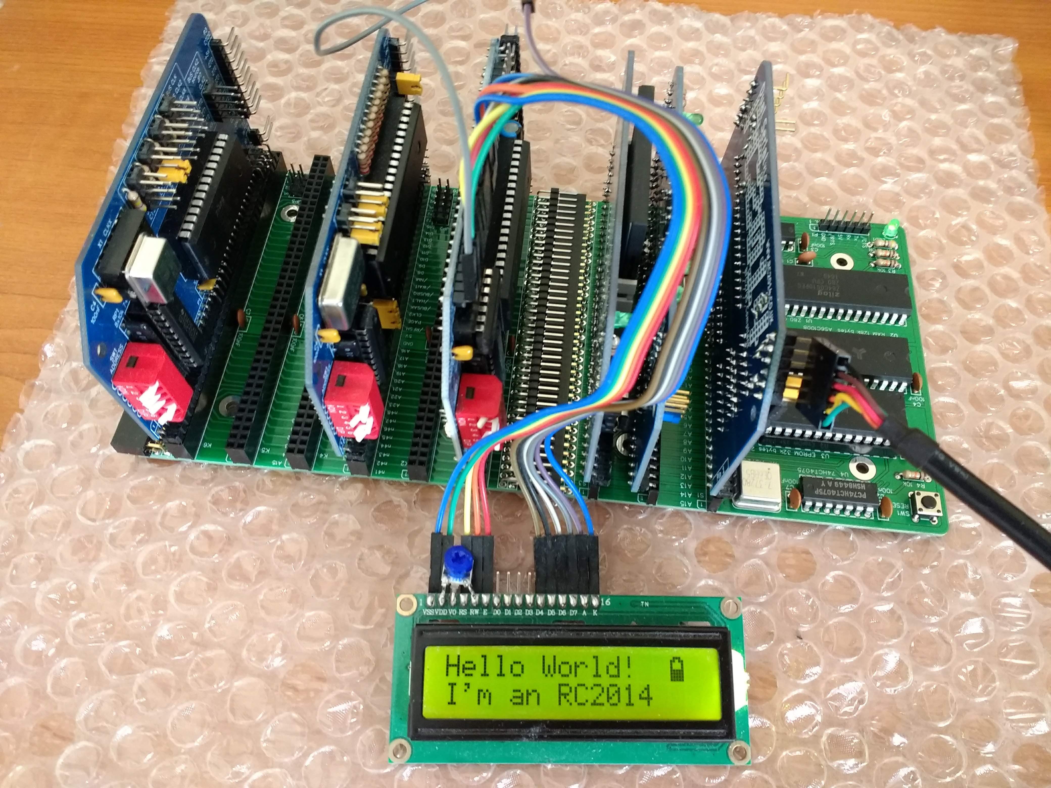
Steve McGrane
Feb 27, 2019, 3:38:57 PM2/27/19
to rc201...@googlegroups.com
Looks good. Can't much argue with the price either.
Thanks!
--
You received this message because you are subscribed to the Google Groups "RC2014-Z80" group.
To unsubscribe from this group and stop receiving emails from it, send an email to rc2014-z80+...@googlegroups.com.
To post to this group, send email to rc201...@googlegroups.com.
To view this discussion on the web, visit https://groups.google.com/d/msgid/rc2014-z80/79e95e8b-717b-4dd7-94a1-cc4980832ba9%40googlegroups.com.
karlab
Feb 27, 2019, 4:01:54 PM2/27/19
to RC2014-Z80
Nice Steve, this is a great offer. Adding a USB adapter and cable is a good idea.
Karl
On Wednesday, 27 February 2019 21:38:57 UTC+1, Steve McGrane wrote:
Looks good. Can't much argue with the price either.Thanks!
On Wed, Feb 27, 2019 at 2:31 PM Steve Cousins <steve...@gmail.com> wrote:
--After much thought and after considering the discussion on this topic, I have decided to offer my "Simpler '14" as a kit on Tindie.Design files remain open sourced via EasyEDA.Documentation and other details can be found at www.scc.me.ukSteve
You received this message because you are subscribed to the Google Groups "RC2014-Z80" group.
To unsubscribe from this group and stop receiving emails from it, send an email to rc2014-z80+unsubscribe@googlegroups.com.
MyklHn
Mar 8, 2019, 5:31:03 PM3/8/19
to RC2014-Z80
Steve,
I remember somewhere you were interested in how long the kits took to arrive. Mine was shipped on Feb 28 and arrive today. I live in Delaware, U.S.A.
Michael
Steve Cousins
Mar 8, 2019, 7:03:15 PM3/8/19
to RC2014-Z80
Thanks, Michael.
I make that 6 working days. Not bad.
Steve
Reply all
Reply to author
Forward
0 new messages