Z80 PIO to Printer
876 views
Skip to first unread message

Augusto Baffa
Feb 16, 2022, 12:55:57 PM2/16/22
to rc201...@googlegroups.com
Hi All,
I have a LX-350 printer with centronics port and I'd like to connect my Rc2014 to it. How could I get it working? There are some PIO boards like Cousins' SC103 but I haven't found anyone showing an application.
I'm wondering if I could use a female parallel connector (DB25) and a centronics cable to have it working like a teletype printer or maybe print a wordstar document.
best,
Augusto Baffa

Alan Cox
Feb 16, 2022, 2:11:51 PM2/16/22
to rc201...@googlegroups.com
If you are willing to overlook a few details then for old style printers it's as simple as wiring some of the centronics pins to a Z80 PIO or the SC103 (although it's not quite got enough pins unless you cheat). It's not strictly correct because the centronics interface should be buffered TTL with smoothing capacitors on it but providing you aren't exposing it to static or leaving it floating around unplugged it should be fine. I suspect simply using 74LS parts on the SC103 buffer chips might be better ?
The full modern protocol is horribly complicated but the original centronics protocol and the only stuff you actually need (or anyone generally implemented until the days of inkjets, lasers and the like is)
Set strobe high
For each byte
Wait for the printer not to be busy
Send the byte
Wait at least 0.5us
Set strobe low for at least 0.5us (with data held)
Set strobe back high (data must remain valid for at least 0,.5us after this)
Wait for printer to lower ACK for at least 5us
End
On a lot of old Z80 systems there weren't enough lines for full centronics out so the low 7bits were wired as data and the top bit on the cable to ground. The top bit of the port was then wired to strobe. That ought to be sufficient to talk the ESC/P protocol.

ladislau szilagyi
Feb 17, 2022, 1:06:34 AM2/17/22
to RC2014-Z80
Hi Augusto,
I suspended the testing when I was able to print a couple of pages; however, I noticed a few missing/doubled chars... but other projects accumulated, and I neglected to conclude the testing.
Some months ago I wrote a parallel printer driver for my RTM-Z80.
I implemented it on RC2014 using SC103 & EPSON LX 350.
It is still under testing...
About the hardware:
I used PIO port B for output (the 8 data bits) and port A as input/output (for BUSY & STROBE ; I did not used ACK).
The main obstacle is the wiring needed to connect SC103 with the male end connector of a cable attached to the printer.
I used some Dupont wires, but needed to adjust them... the result is very fragile & unreliable.
About the software:
It was very difficult to identify the appropriate Z80 instructions needed for the timing (for a 7.3728Mhz Z80)
It took me 2 weeks of experiments.
Examples:
OUT (C),A == failure
OUT (port),a == success
1 NOP == failure , 3 NOP == failure, 2 NOP == success (1 NOP = 0.54u)
Another software issue: how to "limit" the amount of data sent to the printer (the EPSON manual gives a precise printing speeed limit).
I used a software timer (on interrupts), after each print command, to wait an appropriate slice of time.
I suppose that the printer has a buffer for the incoming input, but I prefered to ignore it in order to not assume a buffer overflow risk.
I suspended the testing when I was able to print a couple of pages; however, I noticed a few missing/doubled chars... but other projects accumulated, and I neglected to conclude the testing.
I will resume next week the trials...
regards,
Ladislau
Augusto Baffa
Feb 19, 2022, 10:01:37 AM2/19/22
to rc201...@googlegroups.com
Hi Ladislau ,
I'm thinking of designing a PCB based on SC103 with pinbars and DB25 connector. This will allow us to connect to the printer using a "common" centronics/lpt cable.
And then, adjust the basic Grant Searle's Bios to connect lpt dev to the SC103.
Best,
Augusto Baffa
--
You received this message because you are subscribed to the Google Groups "RC2014-Z80" group.
To unsubscribe from this group and stop receiving emails from it, send an email to rc2014-z80+...@googlegroups.com.
To view this discussion on the web, visit https://groups.google.com/d/msgid/rc2014-z80/8e1956a0-1226-42ac-8ec4-39f9aa123b54n%40googlegroups.com.

Phil G
Feb 20, 2022, 5:51:39 AM2/20/22
to RC2014-Z80
I've done some really simple Centronics interfacing, you can keep it really minimal if thats what you really want.
Some decades ago I did a morse-code to centronics converter in Ham Radio Today mag, it had no RAM at all, just a Z80, PIO and a 2716 eprom.
https://worldradiohistory.com/Archive-DX/Ham-Radio-Today/80s/HRT-1987-01.pdf and https://worldradiohistory.com/Archive-DX/Ham-Radio-Today/80s/HRT-1987-06.pdf
Port B is set up as all outputs (0x0F), and the strobe automagically does its job. For simplicity there were no inputs, I didnt use 'ack' I just delayed after each character which worked perfectly well.
Printing a character is simply a case out outputting it to port B and doing a delay, thats it. Easy peasy lemon squeezy. It all depends on how complex you want it to be.
Cheers
Phil
Alan Cox
Feb 20, 2022, 9:29:19 AM2/20/22
to rc201...@googlegroups.com
On Sun, 20 Feb 2022 at 10:51, 'Phil G' via RC2014-Z80 <rc201...@googlegroups.com> wrote:
I've done some really simple Centronics interfacing, you can keep it really minimal if thats what you really want.Some decades ago I did a morse-code to centronics converter in Ham Radio Today mag, it had no RAM at all, just a Z80, PIO and a 2716 eprom.https://worldradiohistory.com/Archive-DX/Ham-Radio-Today/80s/HRT-1987-01.pdf and https://worldradiohistory.com/Archive-DX/Ham-Radio-Today/80s/HRT-1987-06.pdfPort B is set up as all outputs (0x0F), and the strobe automagically does its job. For simplicity there were no inputs, I didnt use 'ack' I just delayed after each character which worked perfectly well.Printing a character is simply a case out outputting it to port B and doing a delay, thats it. Easy peasy lemon squeezy. It all depends on how complex you want it to be.
My experience is that not doing ACK properly (which is usually about 6 more instructions) actually costs time with all the messing around getting the delays right (and the slower printing). Not all printers have a constant-ish ACK response time either. Plus if you are doing an RTOS the ACK is actually helpful because you can trigger an interrupt on it to service the printer. On the original IBM PC (where this all comes from) it is specifically wired to permit this, although most printer drivers just did busy waits anyway.
Phil G
Feb 20, 2022, 9:41:07 AM2/20/22
to RC2014-Z80
Agreed but my point was that it can be done very simply, centronics doesnt have to be complicated :-)
Phil G
Feb 20, 2022, 9:55:04 AM2/20/22
to RC2014-Z80
>>
On the original IBM PC (where this all comes from)
The Centronics interface predates the IBM PC by ten years!
Alan Cox
Feb 20, 2022, 10:07:20 AM2/20/22
to rc201...@googlegroups.com
On Sun, 20 Feb 2022 at 14:55, 'Phil G' via RC2014-Z80 <rc201...@googlegroups.com> wrote:
>> On the original IBM PC (where this all comes from)The Centronics interface predates the IBM PC by ten years!
It does - but not the PC style interface we were discussing. Whilst the basic Centronics goes back to a quick hack at Wang in 1970 the behaviour we think of today starts with the original IBM PC. At launch time only IBM re-brands of a specific printer actually worked with it. Whether that was classic IBM marketing at work or just how it turned out I don't know.
ladislau szilagyi
Feb 20, 2022, 12:54:19 PM2/20/22
to RC2014-Z80
Hi all,
the topic of "how to send a character to the parallel printer" may seem simple, but in practice it is not so simple (at least in my personal experience, based on interfacing EPSON LX350 with RC2014 via Steven Cousins SC103 PIO board).
First of all, let's see the standard "IEEE Standard Signaling Method for a Bidirectional Parallel Peripheral Interface for Personal Computers" (IEEE 1284 - 2000):
<begin quote>
The Compatibility Mode follows pre-existing industry conventions with eight parallel bits, (Data 1–Data 8) qualified by a low-going pulse on HostClk(nStrobe). The peripheral responds by setting PtrBusy(Busy) high to hold off the next byte until the current one has been removed from the input latch. When ready for the next byte, the peripheral pulses PtrClk(nAck) low, then sets PtrBusy(Busy) low. Timing requirements on peripheral Busy ensure that compliant peripherals will interoperate with existing hosts that monitor Busy but not nAck. After receiving Busy low from the peripheral, hosts shall not set nStrobe low until Tready. The peripheral can reactivate Busy asynchronously due to some condition other than the reception of a data byte. Due to this race condition, the host may at that instant be asserting nStrobe low to send the next data byte. The peripheral shall accept at least one byte from the host after entering a Busy state in this situation. Hosts shall provide Tsetup from D1...D8 and nAutoFd stable to the falling edge of nStrobe.
<end quote>
Of course, the standard specifies also the timings (Tstrobe,Tready,...).
My lesson from the standard was to use only Busy (ignoring Ack) :
for each byte
wait not busy
send byte
wait > 0.75u (as the standard said, but for me only 1.5u worked well)
strobe low
wait > 0.75u (as the standard said, but for me only 1.5u worked well)
strobe high
end
I maintain the data bits stable after strobe high >= 5u, before sending the next char.
I tried also delay loops, but failed.
All other wait intervals (different from 1.5u) resulted in duplicate/missing chars.
The 1.5u was obtained with: NOP, NOP, LD A,R
Between series of chars (<256) sent to the printer, I inserted waiting intervals (on interrupts, using RTM/Z80 timers), in order to be "compatible" with the EPSON LX350 documented printing speed ( 350 chars/second ).
Today I fixed a bug related to the CTC interrupts ( when they occurred "inside" a print command, this resulted in skipped chars at print; now I disable the interrupts until the print command is finished, enabling the interrupts after completing the print command).
The current status: I can now print from a RTM/Z80 task several pages on EPSON, while running other tasks. No more missing chars, only some (few) duplicate chars/page. Still I must investigate these duplicate chars...
regards,
Ladislau
Augusto Baffa
Feb 21, 2022, 11:13:03 AM2/21/22
to rc201...@googlegroups.com
Hi Landislau,
Do you have the wiring schema to connect a sc103 to a parallel port? It's simple but u tested it so if u could send it to us it would be great :)
best,
Augusto
--
You received this message because you are subscribed to the Google Groups "RC2014-Z80" group.
To unsubscribe from this group and stop receiving emails from it, send an email to rc2014-z80+...@googlegroups.com.
To view this discussion on the web, visit https://groups.google.com/d/msgid/rc2014-z80/8eaf5bfd-b616-43ea-9379-1f2ea45d5dc7n%40googlegroups.com.
ladislau szilagyi
Feb 21, 2022, 1:52:23 PM2/21/22
to RC2014-Z80
Hi Augusto,
the wiring is documented in the https://github.com/Laci1953/RTM-Z80/tree/main/SOURCES , file printer.as :
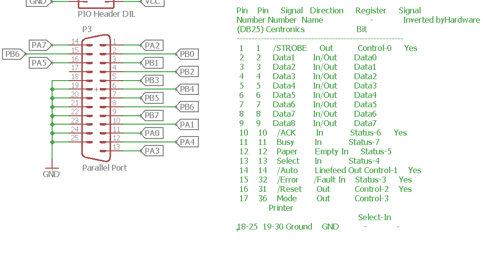
PIO B (output) DATA1 to DATA8 <--> PIN 2 to 9 of "25 PIN MALE" connector
PIO A (input/output) BUSY (bit 0 (INPUT) <--> PIN 11 of "25 PIN MALE" connector) , STROBE (bit 1 (OUTPUT) <--> PIN 1 of "25 PIN MALE" connector)
GND <--> PIN 18 to 25 of "25 PIN MALE" connector
Ladislau
ladislau szilagyi
Feb 27, 2022, 3:35:38 AM2/27/22
to RC2014-Z80
Hi all,
at last, I solved the problem.
Now, dozens of pages can be printed under RTM/Z80, without any character being lost or duplicated !
I published on https://github.com/Laci1953/RTM-Z80/tree/main/SOURCES-Z80AS the updated files (rtsys.as and printer.as).
You can see how to print disk files in RTM/Z80 studying TESTS/tprint.as.
The necessary wiring is documented in SOURCES-Z80AS/printer.as.
How it works: I handle ACK from the printer on interrupts!
So, after STROBE LOW - STROBE HIGH, I wait the interrupt to notify me for the ACK, and only then I continue to send data to the printer. The timings are still important (see SOURCES-Z80AS/printer.as).
I must thank :
- Alan for the hint on using interrupts to handle ACK.
- Steve Cousins for teaching me how to use the interrupt daisy chain on RC2014 (between SC110's SIO and SC103's PIO)
regards,
Ladislau
Augusto Baffa
Feb 27, 2022, 10:35:47 AM2/27/22
to rc201...@googlegroups.com
Hi,

I designed a SC103 Clone with DB25 port and pin header.
I'm using the recent pinout proposed by Landislau.
Best,
Augusto Baffa
To view this discussion on the web, visit https://groups.google.com/d/msgid/rc2014-z80/1ca04c83-b613-416b-bff3-67404a312954n%40googlegroups.com.
ladislau szilagyi
Feb 27, 2022, 12:10:20 PM2/27/22
to RC2014-Z80
Hi Augusto,
very cool!
For the pinout, it is essential to have access (for the 25 pin connector) to the following pins:
- 1 : STROBE
- 2 to 9 : DATA
- 10 : ACK
- 11 : BUSY
- 18 to 25 (one of) : GND
Those pins will be connected to PIO A & B.
In my implementation, I have chosen:
- PIO B (mode=output) bits 0 - 7 to be connected to DATA
- PIO A (mode=control) bit 0 (output) to be connected to BUSY
- PIO A (mode=control) bit 1 (input, on interrupts) to be connected to ACK
- PIO A (mode=control) bit 2 (output) to be connected to STROBE
But, this selection of PIO A bits is not mandatory (other bits may be used as well...), the only mandatory thing is to have access to all three printer signals BUSY,ACK,STROBE.
Also, on interrupts, mode 2 must be used (IM2); interrupt daisy chain must be used too.
regards,
Ladislau
Alan Cox
Feb 27, 2022, 3:54:29 PM2/27/22
to rc201...@googlegroups.com
On Sun, 27 Feb 2022 at 15:35, Augusto Baffa <augb...@gmail.com> wrote:
Hi,I designed a SC103 Clone with DB25 port and pin header.I'm using the recent pinout proposed by Landislau.


You want 74HCT for the decoder parts, but I am guessing you've just not changed the KICAD labels.
Personally I would put 74LS buffers on the output and input lines to get a bit more protection and strong drive (especially as you clearly have the board space), but I may just be being a bit paranoid about leaving CMOS parts exposed to random static build ups on cables.
Alan
Augusto Baffa
Apr 15, 2022, 11:04:25 PM4/15/22
to rc201...@googlegroups.com
Hi Alan,
I used 74LSXX components. I've just finished a demo that works to print a sequence of chars and can be used as reference to another printing tasks.

I'll record a video tomorrow showing it running. The board works using dupont wires or db29 and I've tested on my Epson LX350.
------------------------------------------------------------------------
1 REM ******************************
2 REM * Z80 PIO - PRINTER DEMO *
3 REM * Compatible with SC103 *
4 REM * Z80 PIO MODULE (RC2014) *
5 REM ******************************
6 REM * by Augusto Baffa *
7 REM * https://github.com/abaffa *
8 REM ******************************
9 REM SET PIO AND RESET PRINTER AN
10 OUT &H68,0
20 OUT &H69,0
30 OUT &H6A, &HCF
40 OUT &H6A, &H5B
50 OUT &H6B, &HF
60 OUT &H68, &H24
70 GOSUB 1000
99 REM GENERATE ASCII LIST
100 FOR B = 32 TO 127
110 PRINT CHR$(B);
120 GOSUB 2000
130 NEXT B
140 GOTO 100
150 END
999 REM FORCE A PAUSE
1000 FOR I = 1 TO 5
1010 NEXT I
1020 RETURN
1999 REM SEND DATA TO PRINTER
2000 OUT &H69, B
2010 OUT &H68, &HA0
2020 GOSUB 1000
2030 OUT &H68, &HA4
2040 IF (INP(&H68) AND 3) = 3 THEN GOTO 2050
2050 RETURN
------------------------------------------------------------------------
--
You received this message because you are subscribed to the Google Groups "RC2014-Z80" group.
To unsubscribe from this group and stop receiving emails from it, send an email to rc2014-z80+...@googlegroups.com.
To view this discussion on the web, visit https://groups.google.com/d/msgid/rc2014-z80/CAK9X0%2BtS%2BskEbrnFsJSb0gnSzFNsNhyYy0Y-qbQ8AmgBaSx_QQ%40mail.gmail.com.
Phil G
Jun 28, 2023, 8:05:24 AM6/28/23
to RC2014-Z80
ladislau:>>𝘵𝘩𝘦 𝘵𝘰𝘱𝘪𝘤 𝘰𝘧 "𝘩𝘰𝘸 𝘵𝘰 𝘴𝘦𝘯𝘥 𝘢 𝘤𝘩𝘢𝘳𝘢𝘤𝘵𝘦𝘳 𝘵𝘰 𝘵𝘩𝘦 𝘱𝘢𝘳𝘢𝘭𝘭𝘦𝘭 𝘱𝘳𝘪𝘯𝘵𝘦𝘳" 𝘮𝘢𝘺 𝘴𝘦𝘦𝘮 𝘴𝘪𝘮𝘱𝘭𝘦, 𝘣𝘶𝘵 𝘪𝘯 𝘱𝘳𝘢𝘤𝘵𝘪𝘤𝘦 𝘪𝘵 𝘪𝘴 𝘯𝘰𝘵 𝘴𝘰 𝘴𝘪𝘮𝘱𝘭𝘦 (𝘢𝘵 𝘭𝘦𝘢𝘴𝘵 𝘪𝘯 𝘮𝘺 𝘱𝘦𝘳𝘴𝘰𝘯𝘢𝘭 𝘦𝘹𝘱𝘦𝘳𝘪𝘦𝘯𝘤𝘦,
I was beginning to doubt my recollection from decades ago, but I recently found my old hand-wired Z80 board with its PIO driving a Centronics printer using the simple method I mentioned above. It does work and its as simple as can be!
I use port B with PIO pins 17 (/bstrb ) and 21 (brdy) connected together (as per Zilog user manual) then inverted with a spare gate to give the Centronics strobe. There is no busy, only data, strobe and ground are wired to the centronics plug. Printing is is simply a case of OUT(PORTB), CHAR and delay (say) 50ms or whatever. I realise this is too minimal for those who want to print at full speed, but finding this board has at least confirmed that I've not lost my marbles just yet, the simple method 𝘥𝑜𝘦𝑠 work! :)
Cheers
Phil
Alan Cox
Jun 28, 2023, 9:09:37 AM6/28/23
to rc201...@googlegroups.com
the Centronics strobe. There is no busy, only data, strobe and ground
are wired to the centronics plug. Printing is is simply a case of
OUT(PORTB), CHAR and delay (say) 50ms or whatever. I realise this is
too minimal for those who want to print at full speed, but finding
this board has at least confirmed that I've not lost my marbles just
yet, the simple method 𝘥𝑜𝘦𝑠 work! :)
If your printer has modes that are 7bit clean (as almost all do) you
are wired to the centronics plug. Printing is is simply a case of
OUT(PORTB), CHAR and delay (say) 50ms or whatever. I realise this is
too minimal for those who want to print at full speed, but finding
this board has at least confirmed that I've not lost my marbles just
yet, the simple method 𝘥𝑜𝘦𝑠 work! :)
can just repurpose bit 7 as an input and pull the printer bit 7 down.
It's also possible to use a spare CTC channel to "count" the ack.
Alan
Reply all
Reply to author
Forward
0 new messages