82c55 IDE adapter
1,971 views
Skip to first unread message

Ed Brindley
Sep 11, 2017, 5:08:17 PM9/11/17
to RC2014-Z80
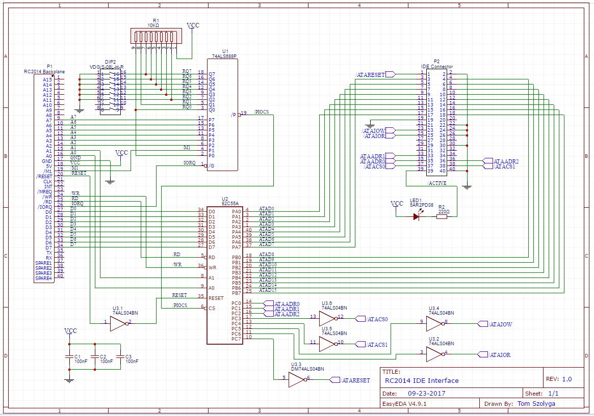
As per comments in the Fuzix thread, I had a go at coming up with a schematic for a 82c55 IDE adapter for the RC2014.
It's a clone of Philip's YAZ180 design with added '688 based address decoding (thanks to PianoMatt and various S100 designs. I looked at this one: https://www.retrobrewcomputers.org/lib/exe/fetch.php?media=boards:ecb:ramfloppy:printing_ecb-ramf-r11.sch.pdf), and a 40pin IDE connector.
One thing I'm not sure about is the IDE INTRQ signal. Attaching this directly to the Z80s interrupt line seems like a bad idea if we want to be able to use the Z80 in interrupt mode 2, which is ideally what you'd want to do when using the Z80 peripheral chips, the CTC, SIO etc.
I'm wondering if attaching it is necessary? Other designs seem to not connect it, e.g. ECB diskio https://www.retrobrewcomputers.org/lib/exe/fetch.php?media=boards:ecb:diskio-v3:ecb_diskio_v3_-_schematics_-_color_1.0.pdf
All comments welcome! I knocked it up quickly so will definitely be some errors...
Cheers,
Ed

codifies
Sep 11, 2017, 5:30:11 PM9/11/17
to RC2014-Z80
I did wonder about different strategies for putting the interrupt vector on the lower half of the address bus without using loads or logic, while not (hopefully) needed for this I was wondering if anyone had had any thought about elegant ways to do this...

phillip.stevens
Sep 11, 2017, 8:20:48 PM9/11/17
to RC2014-Z80
On Tuesday, 12 September 2017 07:08:17 UTC+10, Ed Brindley wrote:
As per comments in the Fuzix thread, I had a go at coming up with a schematic for a 82c55 IDE adapter for the RC2014.
It's a clone of Philip's YAZ180 design with added '688 based address decoding (thanks to PianoMatt and various S100 designs. I looked at this one: https://www.retrobrewcomputers.org/lib/exe/fetch.php?media=boards:ecb:ramfloppy:printing_ecb-ramf-r11.sch.pdf), and a 40pin IDE connector.
Looks very good!
Some review points.
- The 82C55 RESET is a positive signal, unlike the Z80 /RESET signal. (Perhaps steal the interrupt inverter?).
- My errata. I just remembered the PDF I gave as input is a little bit dated (wrong). I connected DA0 and DA1 each on the wrong pin of the IDE connector, so they are reversed. But, as I noted, it is easy to change pin-out with software defines. The driver defines shows exactly how mine are really connected. Either way, doesn't matter.
One thing I'm not sure about is the IDE INTRQ signal. Attaching this directly to the Z80s interrupt line seems like a bad idea if we want to be able to use the Z80 in interrupt mode 2, which is ideally what you'd want to do when using the Z80 peripheral chips, the CTC, SIO etc.
I'm wondering if attaching it is necessary?
The interrupt is unnecessary for the IDE interface, IMHO. All the drivers I've seen don't use it, and I didn't use it either. Since modern PATA drives have large caches (by our standards) they tend to respond pretty quickly. Since we're using PIO Mode (the slowest mode for the drive) I guess there's nothing to lose by doing the standard polling method.
I implemented the interrupt just to keep the interface general. I wanted to have some method of having something at the other end of the cable being able to interrupt the CPU. And I had an inverter gate spare to make it line up with the Z180 interrupt /INT0. In my next revision of hardware, I'll be changing the /INT0 handling again, because my current implementation doesn't support the 82C55 interrupt pin, which is useful for keyboard scanning, etc (which was another oversight).
I'm not sure how to handle this on the Z80, because there are not so many interrupt lines available. Perhaps just a jumper...?
All comments welcome! I knocked it up quickly so will definitely be some errors...
Final comment. I decided to use the 44pin lap-top IDE pin-out, because it carries power for the drive, and is physically smaller. This made the solution 1 cable, rather than needing to power the drive from a separate molex connector and power supply. The 44pin interface also helps for transporting data, as I have some old USB external lap-top drives, which I can use to simply move data between PC and Z80. And, the result looks really tidy, IMHO.

Looking forward to getting a RC2014 IDE interface soon. ;-).

PianoMatt
Sep 17, 2017, 8:45:17 AM9/17/17
to RC2014-Z80
I was thinking about this yesterday when I was messing about with the CF card in RomWBW. Basing it on this design would maintain compatibility with the RetroBrew designs and thus RomWBW.
Have you started a layout for it? If you decide not to let me know and I'll have a crack at it
PianoMatt
Have you started a layout for it? If you decide not to let me know and I'll have a crack at it
PianoMatt
Ed Brindley
Sep 17, 2017, 3:05:10 PM9/17/17
to RC2014-Z80
Hi Matt,
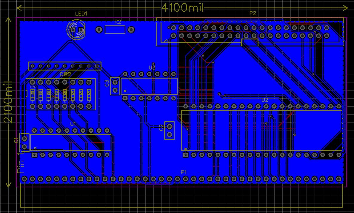
Yeah I've started the layout, but going down to London for the Hackaday unconference has got in the way of me finishing it off!
Screenshot attached of current state of play. I'd started ripping up a few tracks and rerouting things so there's a few tracks missing!
I've gone for both a 40 pin and 44 pin connector so everyone should be happy. The 40 pin is a right angle on on the edge so you could use it with a CF adapter.
Re the pin assignment, I went with Philip's variation (see the Fuzix thread for details) so you would have to swap a couple of the RomWBW defines around... Now thinking that maybe should just go with the same as the other RetroBrew interfaces though.
Cheers,
Ed
PianoMatt
Sep 17, 2017, 3:16:27 PM9/17/17
to RC2014-Z80
I might have a go at doing a layout for the DIP40 version. I've got a few of them laying around, and Mouser still stocks them.
phillip.stevens
Sep 18, 2017, 9:33:43 PM9/18/17
to RC2014-Z80
Ed,
I've gone for both a 40 pin and 44 pin connector so everyone should be happy. The 40 pin is a right angle on on the edge so you could use it with a CF adapter.
Sound like the best plan, to cover both options.
Re the pin assignment, I went with Philip's variation (see the Fuzix thread for details) so you would have to swap a couple of the RomWBW defines around... Now thinking that maybe should just go with the same as the other RetroBrew interfaces though.
I've checked out the RetroBrew solution, and they use an PPIDE adapter mini-board which avoids the "lock-in" created by the inverters on the 82C55 input pins, for their SBCs. So their main on-board 82C55 Parallel Port interface is just straight pins.
The IDE interface is created by another PPIDE mini-board adapter attached in between the 82C55 and the IDE drive, and it carries the inverters necessary to drive the IDE bus. Since the PPIDE mini-board is a special purpose interface they don't care about Mode 1 applications (keyboard scanning, CRT, parallel printing), or Mode 2 applications (Floppy Controller) so they just "numbered off" the interface pins, using Port C for control.
The current RetroBrew PPIDE mini board uses exactly the same pin-out solution as Paul Stoffregen, and Peter Faasse before him, leaving PC0, PC1, and PC2 for the IDE address pins (non-inverted). This adapter mini-board can only do Mode 0, for IDE, which is ok for this application.
Therefore, IMHO, if you're building your 82C55 board exclusively to be an IDE interface then you're best to follow along with Peter's, Paul's, and RetroBrew's solution. Otherwise (because you're not proposing a PPIDE adapter in between), keep PC2, PC4, and PC6 for the IDE address pins and keep your interface general purpose.
Either way, it is just a redefinition of the pins in the driver.
Related to the IDE interface. AA from z88dk has finished a z88dk-lib tool, which enables third party libraries to be installed into your z88dk installation, and eases inclusion and linkage of these libraries into projects. I'm currently finishing ChaN's FatFs code port in my z88dk-libraries repository, and have it connected to my diskio layer. This means as soon as your 82C55 board is finished, we can move the diskio support to rc2014, and then compile a FatFs implementation. The software heavy lifting is done.
Cheers, Phillip
Ed Brindley
Sep 19, 2017, 7:54:22 PM9/19/17
to RC2014-Z80
Thanks Philip,
At the moment just going for an IDE interface, so have reverted to the RetroBrew pinout. Figure if need one for general purpose use can spin another PCB.
I've inverted the reset line and have swapped DA0/DA1 around from previous schematic.
Cheers,
Ed
At the moment just going for an IDE interface, so have reverted to the RetroBrew pinout. Figure if need one for general purpose use can spin another PCB.
I've inverted the reset line and have swapped DA0/DA1 around from previous schematic.
Cheers,
Ed
phillip.stevens
Sep 19, 2017, 9:02:05 PM9/19/17
to RC2014-Z80
Hi Ed,
At the moment just going for an IDE interface, so have reverted to the RetroBrew pinout. Figure if need one for general purpose use can spin another PCB.
Looks good!
But, for the cost of four jumper-holes, it seems like a bit of a waste to PLAN to build two PCBs.
Why not put in some jumper-holes and trace-cut options to allow the PC4 and PC6 to be swapped around with PC0 and PC1 (on the input side of the inverters)?
It would save creating another SKU, and give you some flexibility to use your PPI board for multiple purposes.
The IDE interface is created by another PPIDE mini-board adapter attached in between the 82C55 and the IDE drive, and it carries the inverters necessary to drive the IDE bus. Since the PPIDE mini-board is a special purpose interface they don't care about Mode 1 applications (keyboard scanning, CRT, parallel printing), or Mode 2 applications (Floppy Controller).
The current RetroBrew PPIDE mini board uses exactly the same pin-out solution as Paul Stoffregen, and Peter Faasse before him, leaving PC0, PC1, and PC2 for the IDE address pins (non-inverted).
Just because Peter and Paul didn't think forward to other applications, doesn't mean we have to blindly follow in their footsteps. ;-)
Cheers, Phillip
PianoMatt
Sep 19, 2017, 9:13:59 PM9/19/17
to RC2014-Z80
Are the other modes of operation that the 82C55 is capable of useful in the context of an IDE interface?
Cloning the DiskIO board makes sense to me,because it makes it easier to implement RomWBW on the RC. It'd be great to see the RC become officially supported by RomWBW, and adding the standard IDE interface to the RC arsenal could bring us one step closer.
Cloning the DiskIO board makes sense to me,because it makes it easier to implement RomWBW on the RC. It'd be great to see the RC become officially supported by RomWBW, and adding the standard IDE interface to the RC arsenal could bring us one step closer.
phillip.stevens
Sep 19, 2017, 10:00:42 PM9/19/17
to RC2014-Z80
Are the other modes of operation that the 82C55 is capable of useful in the context of an IDE interface?
Hi Matt,
what you're asking is actually backwards, IMHO.
The IDE interface is a very specific implementation based on the use of a 8255 parallel port interface chip that was designed to be very general in nature.
The question to ask, IMHO, is actually "If I'm building an interface board with a 8255 on it, why would I lock myself into just building it for one single application, when it is possible to allow it to be very general?"
Cloning the DiskIO board makes sense to me, because it makes it easier to implement RomWBW on the RC. It'd be great to see the RC become officially supported by RomWBW, and adding the standard IDE interface to the RC arsenal could bring us one step closer.
Cloning RomWBW is no easier or harder with a slightly different pin-out for the 8255. We're talking two bits here.
You still need to compile RomWBW for our specific addressing IO_BASE addressing. That will change depending on where the 8255 card is located.
The other changes in the source code are very simply moving two bits in the 8255 to IDE assignment. It is that easy.
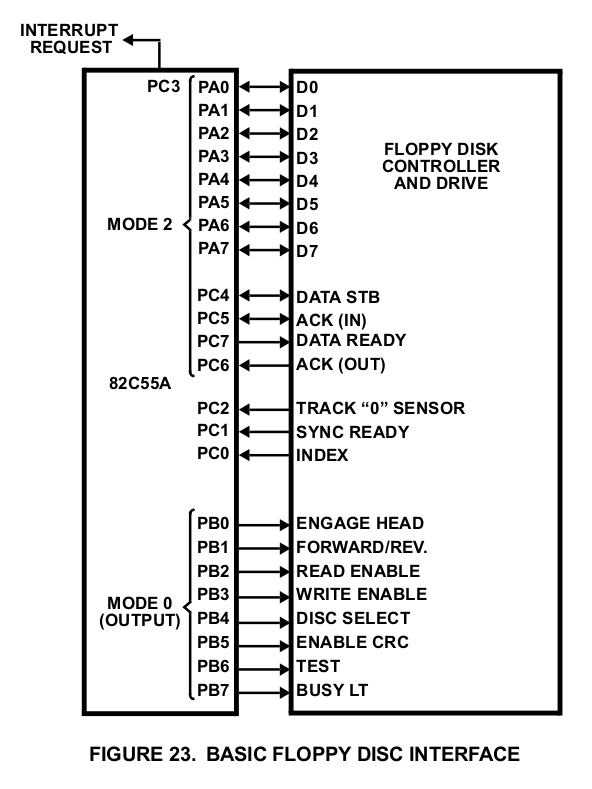
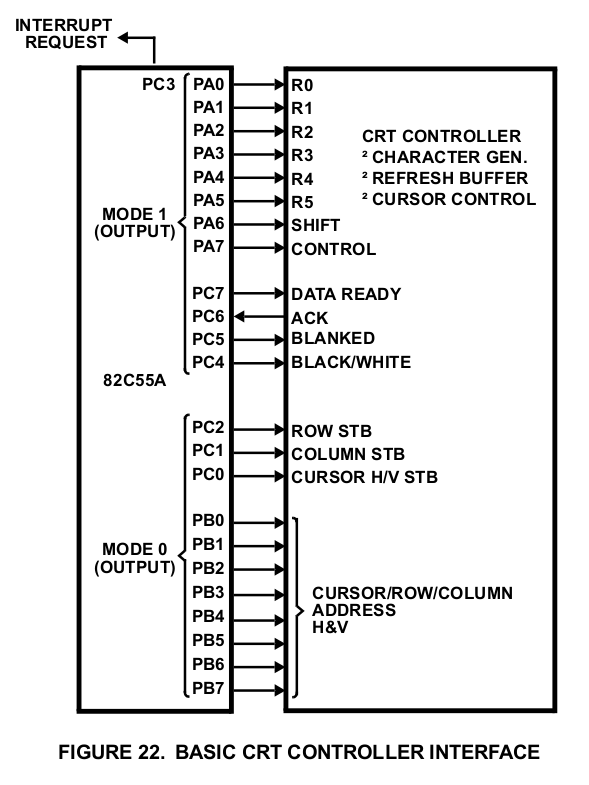
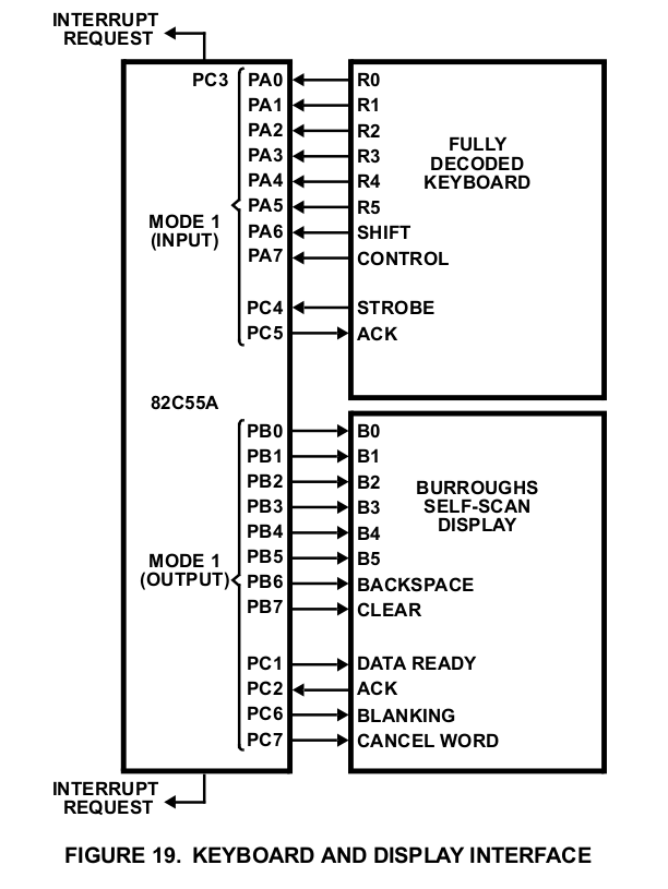
On the topic of what else an 8255 can do, the data sheet has some examples.
They include:
- Keyboard and Display Interface (Mode 1)
- Parallel Printer Interface (Mode 1)
- CRT Controller (Mode 1)
- Floppy Disc Interface (Mode 2)
All of these examples (and there are others, but I'm getting long winded), are enabled just by swapping PC0 for PC4, and PC1 for PC6 on the 8255 interface hardware, and moving two bits on the RomWBW software defines.
Cheers, Phillip
PianoMatt
Sep 20, 2017, 5:18:29 AM9/20/17
to RC2014-Z80
I think it would definitely be easier to keep the board dedicated to IDE in all honesty. The form factor of the cards is very small, so trying to squeeze all the extra stuff on there to support IDE as well as general purpose use is difficult. Sounds like what you want is a general purpose 82C55 board with PA, PB and PC all broken out. Maybe give it a go yourself?
PianoMatt
Ed Brindley
Sep 20, 2017, 8:21:31 AM9/20/17
to RC2014-Z80
Hi Phillip,
Will be interesting to see what kind of performance you get vs bit banging the compactflash card in 8 bit mode. I expect it's not going to make any difference at all.
What speed do you run the Z180 on your YAZ180? I was looking at an S100 82c55 design, and they'd added some logic to latch signals to enable it to work on buses > 8Mhz.
Matt, yes our schematics are almost identical! Ah well, it's never wasted time if you're enjoying it / learning IMO :)
Thanks for the critique.
Will add some jumpers to swap those round and send it off to get a PCB made. Hopefully I've not missed anything else, although wary as I've not prototyped this!
Will be interesting to see what kind of performance you get vs bit banging the compactflash card in 8 bit mode. I expect it's not going to make any difference at all.
What speed do you run the Z180 on your YAZ180? I was looking at an S100 82c55 design, and they'd added some logic to latch signals to enable it to work on buses > 8Mhz.
Matt, yes our schematics are almost identical! Ah well, it's never wasted time if you're enjoying it / learning IMO :)
Cheers,
Ed
phillip.stevens
Sep 20, 2017, 9:05:13 AM9/20/17
to RC2014-Z80
Hi Ed,
Will add some jumpers to swap those round and send it off to get a PCB made. Hopefully I've not missed anything else, although wary as I've not prototyped this!
Fingers crossed for you.
Will be interesting to see what kind of performance you get vs bit banging the compactflash card in 8 bit mode. I expect it's not going to make any difference at all.
I don't really know, but I expect you're right. The throughput will be strongly limited by the Z80 bus, and therefore back to clock speed.
I should do some file read / write tests, now I have an accurate clock, and FatFs file system.
PJRC has this to say "The faster version was used in a project that sustained reads of 24 kBytes/sec, while also doing some serial communication, with a 14.7456 MHz system clock. The normal version is believed to be able to read at about 16 kBytes/sec, but this hasn't been verified."
What speed do you run the Z180 on your YAZ180? I was looking at an S100 82c55 design, and they'd added some logic to latch signals to enable it to work on buses > 8Mhz.
I'm running my YAZ180 at 18.432MHz Phi. The 82C55 works ok with this, provided you use 2 wait states for I/O. With exception of the APU, it is the slowest device on the bus. The Z180 is very flexible in this regard, allowing wait states for RAM and I/O to be separately specified.
Keeping the Phi below 20MHz means that I can run zero wait state RAM and Flash, and also I can get away with the internal clock at 2xPhi, overclocking the core to 36.864MHz.
To get the Am9511A APU to understand writes I have to halve the Phi to 9.216MHz because it needs 30ns of /CS hold after /WR is released. The Z180 has a special E-Clock timing to support this. But, at 18.432MHz, the /CS hold is 27ns, (1/2 Phi) which is not enough... Doh!
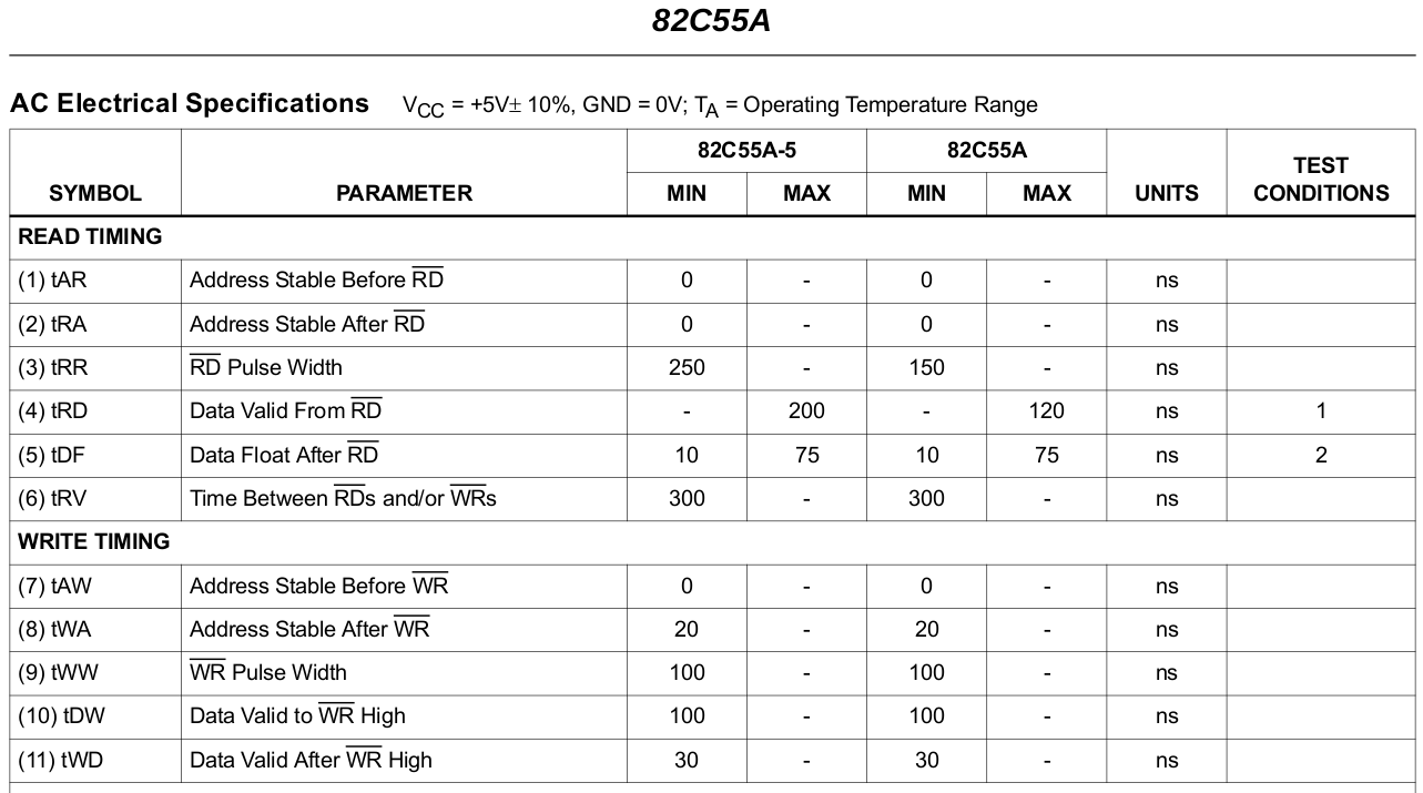
Now that I am reminded about this, the 82C55 also has special /WR timing requirements...
Originally I had it broken, and this is the fix.
The 82C55 needs "tWA" (Address Stable after /WR) to be 20ns. This means the /CS must be generated from just the address lines in Z180 world.
Don't incorporate the /IORQ line in the /CS calculation, or the /CS will be tied to the /WR (/IORQ) timing, rather than to the address validity timing.
The Z180 only promises 5ns of tAH hold time but, since I've buffers on the lower address lines that hold the previous state until driven to a new state, it works out ok.
The Z80 promises 1/2 Phi of address validity after /WR and /IORQ, so if you just use addresses to generate /CS then it is sweet.
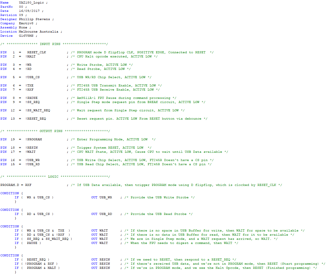
I use EEPLD to generate /CS, so I could be as complex as I wanted to generate these, and originally I used the /IREQ as part of the calculation.
Now, I've removed it and just have a NOT /MREQ term (so that the /CS is not needlessly triggered).
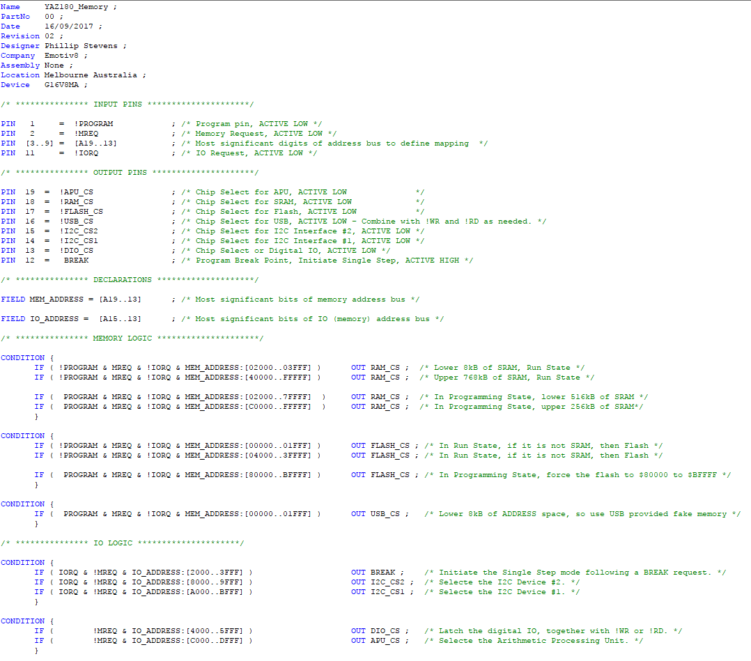
See CUPL attached for more clarity.
Got my fingers crossed it works out.
Soon as you see the board, I'll copy the z88dk 8255 -> ide -> diskio drivers over to the RC2014 target.
Cheers, Phillip
phillip.stevens
Sep 21, 2017, 10:34:23 AM9/21/17
to RC2014-Z80
Hi Ed,
Will be interesting to see what kind of performance you get vs bit banging the compact flash card in 8 bit mode. I expect it's not going to make any difference at all.
Well the question is intriguing enough to make it worth a bit of an investigation. So, I took my `diskio.c` test program, put in some timing captures and increased the sector count to 32 (512 byte) sector writes and reads. And the results are in.
Kingspec-SSD KSD-PA18.6-XXXMS 16kB W/R in 14 /256th of a second or 292kB/s.
that seems like quite fast... so lets try an old IBM drive.
IBM-Travelstar DBCA-206480 16kB W/R in 15-21 /256th of a second or 195kB/s to 273kB/s.
Here's an excerpt from the IBM-Travelstar tests, showing the variability of the result.
Note the drive is synced between each write and read, so it not just reading cached data.
**** Test cycle 2 of 3 start ****
disk_initalize(0) - ok.
**** Get drive serial number ****
disk_ioctl(0, ATA_GET_SN, 0xA083) - ok.
Serial number of the drive 0 is HR0RRQG3912.
**** Get drive size ****
disk_ioctl(0, GET_SECTOR_COUNT, 0x8191) - ok.
Number of sectors on the drive 0 is 12685680.
**** Get sector size ****
disk_ioctl(0, GET_SECTOR_SIZE, 0x8195) - ok.
Size of sector is 512 bytes.
**** Multiple sector write test ****
disk_write(0, 0xA083, 1, 32) - ok.
the 16kB write time taken was 0 + 15/256 seconds
disk_ioctl(0, CTRL_SYNC, NULL) - ok.
disk_read(0, 0xA083, 1, 32) - ok.
the 16kB read time taken was 0 + 16/256 seconds
Data matched.
disk_write(0, 0xA083, 1, 32) - ok.
the 16kB write time taken was 0 + 21/256 seconds
disk_ioctl(0, CTRL_SYNC, NULL) - ok.
disk_read(0, 0xA083, 1, 32) - ok.
the 16kB read time taken was 0 + 17/256 seconds
Data matched.
disk_write(0, 0xA083, 1, 32) - ok.
the 16kB write time taken was 0 + 21/256 seconds
disk_ioctl(0, CTRL_SYNC, NULL) - ok.
disk_read(0, 0xA083, 1, 32) - ok.
the 16kB read time taken was 0 + 17/256 seconds
Data matched.
Impressive!

Tom Szolyga
Sep 21, 2017, 8:50:47 PM9/21/17
to RC2014-Z80
There may be an error in this version of the schematic. It looks like the connections to Vcc and GND in the address decoding section were switched. As the schematic is I think the 82C55 will be selected only when /M1 is active or LOW or equal to gnd.
Best regards,
Tom
Ed Brindley
Sep 22, 2017, 3:48:14 AM9/22/17
to RC2014-Z80
Thanks Tom,
Yes I've got that the wrong way round!
Awaiting a few bits then going to try it on breadboard before I commit to a PCB.
Thanks,
Ed
Ed Brindley
Sep 22, 2017, 7:09:58 AM9/22/17
to RC2014-Z80
That's faster than I imagined.
So regarding the z88dk stuff, there's the 82c55 driver then diskio layered over that as an abstraction and c interface, then FatFS on top of that?
And you could theoretically build this into a CP/M program? (the COM file would have to reside on a normal CP/M formatted drive, but you could load data in-program from a FAT partition on a different drive?)
Cheers,
Ed
phillip.stevens
Sep 22, 2017, 8:14:33 AM9/22/17
to RC2014-Z80
Hi Ed,
That's faster than I imagined.
Yes, it is faster than I imagined too. By 10x what PJRC mentioned on his web site. The performance is purely driven by the number of reads and writes to the 82C55, so I used the Z80 ini and outi to great benefit, allowing me to run the interface more efficiently than PJRC was doing with his 8051 code. And, I've specifically written only byte and sector transfer routines, and tried to optimise for that. PJRC went about it a bit differently.
So regarding the z88dk stuff, there's the 82c55 driver then diskio layered over that as an abstraction and c interface, then FatFS on top of that?
It is actually driven by ChaN's FatFs. This is a library written by a Japanese benefactor, which has all the latest FatFs stuff in it, including exFAT, and all of the LFN and Unicode tables. This library relies on a standardised set of diskIO calls that, once they're passing the provided test code, enables you to run ChaN's FatFs library with confidence that nothing is broken.
Unfortunately, sdcc (used in the z88dk) doesn't have the ability to put functions and data into sections by itself. This means that the single file (ff.c) library fills up a lot of space, because the linker can't decide which sections to abandon.
The only short term (actually medium to long term) fix is to scatter ChaN's work down into individual function files, so that the z88dk linker can decide which functions are being used, and which ones can be abandoned. This, I've now done partially and it is working enough to at least pass the basic tests.
I'll be checking this segmentation work further soon, and hopefully getting some performance figures too.
And you could theoretically build this into a CP/M program? (the COM file would have to reside on a normal CP/M formatted drive, but you could load data in-program from a FAT partition on a different drive?)
Yes. Absolutely.
Actually I have a cunning plan, and that is to build a "modern" CP/M2.2 platform with FAT32 disks, and memory banking similar to ZDOS, potentially looking quite a bit like (if not the same as) FUZIX, that can run CP/M applications without all the mucking about with inefficient file types and other limitations from the 1980s. Admittedly, one should produce running code before one mouths off about stuff. But, it is a medium - long term outcome focus for me.
Will be interesting to see what kind of performance you get vs bit banging the compact flash card in 8 bit mode. I expect it's not going to make any difference at all.Well the question is intriguing enough to make it worth a bit of an investigation. So, I took my `diskio.c` test program, put in some timing captures and increased the sector count to 32 (512 byte) sector writes and reads. And the results are in.Kingspec-SSD KSD-PA18.6-XXXMS 16kB W/R in 14 /256th of a second or 292kB/s.that seems like quite fast... so lets try an old IBM drive.IBM-Travelstar DBCA-206480 16kB W/R in 15-21 /256th of a second or 195kB/s to 273kB/s
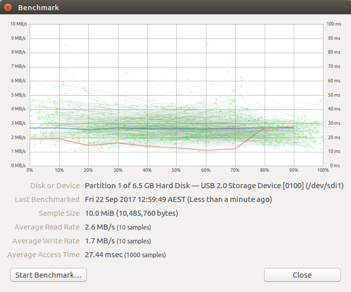
On this topic, I got enthusiastic, and tested both these drives (and another Samsung from 2006 I had to hand) using my USB<->PATA mini external drive. Because it is a USB interface, it is not exploiting all the benefits of PATA-IDE, but still there's no finesse to the outcome.
The IBM-Travelstar (from Oct '99) is being driven to about 10% of capacity by the 82C55, but the modern SSD is running about 1% of capacity (again, on a USB interface). So, don't waste money on SSDs for your RC2014-82C55-IDE interface, I think is the message.
I'll try some C interface (FatFs) speed testing, of file copies, etc, to see how much performance is lost between C wrapped asm diskIO functions, and the FatFs calls.
Cheers, Phillip
Tom Szolyga
Sep 22, 2017, 6:24:56 PM9/22/17
to RC2014-Z80
Hi Ed and Phillip,
Have you looked at an app called "RUNCPM"? There are versions that run on multiple O/Ss; I have tried the Windows version. The app runs stock CP/M programs in a window on a PC. The stock CPM program accesses standard PC files. There is a directory for each CPM drive. Ex PC directory A corresponds to CPM drive A. I believe RUNCPM does this by replacing the BDOS and BIOS layers in CPM, while running the stock CCP layer. Seems to me the same think could be done on the Z80 to access media formatted in FATxx fashion.
Thoughts?
Best regards,
Tom
phillip.stevens
Sep 23, 2017, 3:21:33 AM9/23/17
to RC2014-Z80
And you could theoretically build this into a CP/M program? (the COM file would have to reside on a normal CP/M formatted drive, but you could load data in-program from a FAT partition on a different drive?)Yes. Absolutely.Actually I have a cunning plan, and that is to build a "modern" CP/M2.2 platform with FAT32 disks, and memory banking similar to ZDOS, potentially looking quite a bit like (if not the same as) FUZIX, that can run CP/M applications without all the mucking about with inefficient file types and other limitations from the 1980s. Admittedly, one should produce running code before one mouths off about stuff. But, it is a medium - long term outcome focus for me.
Have you looked at an app called "RUNCPM"? I believe RUNCPM does this by replacing the BDOS and BIOS layers in CPM, while running the stock CCP layer. Seems to me the same think could be done on the Z80 to access media formatted in FATxx fashion.
Tom,
that I had not seen before, but it looks like exactly the source tree that I'll be leaning on for my cunning plan. Perfect.
Thank you!
That is one of the best things about Z80. It was so popular and successful, you can be sure that you're never the first to attempt something.
Someone will always have done it before.
Cheers, Phillip
phillip.stevens
Sep 23, 2017, 9:58:44 AM9/23/17
to RC2014-Z80
That's faster than I imagined.Yes, it is faster than I imagined too. By 10x what PJRC mentioned on his web site. The performance is purely driven by the number of reads and writes to the 82C55, so I used the Z80 ini and outi to great benefit, allowing me to run the interface more efficiently than PJRC was doing with his 8051 code. And, I've specifically written only byte and sector transfer routines, and tried to optimise for that. PJRC went about it a bit differently.
Will be interesting to see what kind of performance you get vs bit banging the compact flash card in 8 bit mode. I expect it's not going to make any difference at all.Well the question is intriguing enough to make it worth a bit of an investigation. So, I took my `diskio.c` test program, put in some timing captures and increased the sector count to 32 (512 byte) sector writes and reads. And the results are in.
Kingspec-SSD KSD-PA18.6-XXXMS 16kB W/R in 14 /256th of a second or about 292kB/s.
I'll try some C interface (FatFs) speed testing, of file copies, etc, to see how much performance is lost between C wrapped asm diskIO functions, and the FatFs calls.
 total_bytes = 0;
 for (;;)
 {
   res = f_read(&FileIn, buffer, sizeof(buffer), &br);
   if (res || br == 0) break;   /* error or eof */
   res = f_write(&FileOut, buffer, br, &bw);
   total_bytes += bw;
   if (res || bw < br) break;   /* error or disk full */
 }
Well a FatFs simple file copy read -> write file produces between 113kB/s and 118kB/s copied, using the Kingspec-SSD
(which will be no different in speed to any other drive in PIO mode).
So the net FatFS read or write rate is about 220kB/s, so we lose about 70kB/s to the C wrapper and file system management for this simple task.
Cheers, Phillip
Ed Brindley
Sep 23, 2017, 5:01:15 PM9/23/17
to RC2014-Z80
Nice work.
Many thanks for your assistance so far, I have it working on breadboard in RomWBW. (It's taken all day... using a PLCC44 to DIP40 adapter contributed to the confusion)
Many thanks for your assistance so far, I have it working on breadboard in RomWBW. (It's taken all day... using a PLCC44 to DIP40 adapter contributed to the confusion)
I'm wondering about "The 82C55 needs "tWA" (Address Stable after /WR) to
be 20ns. This means the /CS must be generated from just the address
lines in Z180 world.
Don't incorporate the /IORQ line in the
/CS calculation, or the /CS will be tied to the /WR (/IORQ) timing,
rather than to the address validity timing."
It seems to work OK using /IORQ as the CS for the 82c55, and I see the DiskIO V3 design also uses it too... https://www.retrobrewcomputers.org/lib/exe/fetch.php?media=boards:ecb:diskio-v3:ecb_diskio_v3_-_schematics_-_color_1.0.pdf
Any thoughts? As it works I'm inclined to leave it...
Cheers,
Ed
Any thoughts? As it works I'm inclined to leave it...
Cheers,
Ed
Message has been deleted
PianoMatt
Sep 23, 2017, 5:15:42 PM9/23/17
to RC2014-Z80
Ed, are you using a Z80 or a Z180?
Tom Szolyga
Sep 23, 2017, 6:10:23 PM9/23/17
to RC2014-Z80
HI Ed and Philip,
I entered your schematic into EasyEDA using the 40 Pin DIP 82C55. I created a PCB using Auto route nd created the FAB output. (See attached) Fab'ing the board and shipping to me will take about 2 weeks.
Best regards,
Tom
Tuesday, September 19, 2017 at 4:54:22 PM UTC-7, Ed Brindley wrote:
phillip.stevens
Sep 23, 2017, 6:21:20 PM9/23/17
to RC2014-Z80
I'm wondering about "The 82C55 needs "tWA" (Address Stable after /WR) to be 20ns. This means the /CS must be generated from just the address lines in Z180 world.Don't incorporate the /IORQ line in the /CS calculation, or the /CS will be tied to the /WR (/IORQ) timing, rather than to the address validity timing."
It seems to work OK using /IORQ as the CS for the 82c55, and I see the DiskIO V3 design also uses it too... https://www.retrobrewcomputers.org/lib/exe/fetch.php?media=boards:ecb:diskio-v3:ecb_diskio_v3_-_schematics_-_color_1.0.pdf
Any thoughts? As it works I'm inclined to leave it...
Congrats. ;-)
I think the 82C55 is more forgiving than the datasheet promises as, IIRC, it think it was actually working (with my tight z180 timing) before I retrospectively fixed it to match the datasheet requirements.
But the datasheets are pretty clear about what it needs. I've cut out the relevant pieces just to make it easier to reference.
82C55A needs these timings tWA 20ns and tWD 30ns.
Z80 provides a delta of 10ns between tDH /IORQ and tDH /WR.
So if you tie your 82C55A /CS into the Z80 /IORQ line then you won't be getting the 30ns specified.
The Z80 address validity is 1/Phi longer, so it can generate the proper /CS until the 1/Phi is too short to hold the required timing.
So, YMMV depending on the actual chips you have to hand, I think is my thought.
Cheers,
PianoMatt
Sep 23, 2017, 6:56:54 PM9/23/17
to RC2014-Z80
I've sent off using EasyEDA's fab service too. Didn't use their software though, I prefer KiCAD. First time using them to make boards, so hopefully they will do a good job
PianoMatt
Sep 23, 2017, 7:15:06 PM9/23/17
to RC2014-Z80
Looking at the datasheet, aren't those values the minimum required rather than an absolute requirement? As in the chip won't function if the timing are shorter than 20ns?
phillip.stevens
Sep 23, 2017, 11:48:52 PM9/23/17
to RC2014-Z80
Looking at the datasheet, aren't those values the minimum required rather than an absolute requirement?
As in the chip won't function if the timing are shorter than 20ns?
The 82C55 datasheet is saying, "I required a minimum of 20ns of address lines stability, and 30ns of data lines stability after my /WR line is raised, to latch your data lines properly."
It is also saying that "I need your /WR pulse to be no less than 100ns."
All three of these values are specified by the manufacturer.
If you don't hold these values, then your mileage may vary.
You might have good chips that work today, but then don't work in summer, or on Tuesdays, or whatever.
If you're designing a product that has to work anywhere and it is mission critical then you pay attention to these values.
Otherwise, if it works be happy. ;-).
I'm only being a datasheet pedant because of the recent experience I had with the Am9511A, that was specified at 30ns for one particular timing, and I gave it 27ns, and it didn't work.
I also tried to clock it at 3.072MHz (specified to 3.0MHz) and it also didn't work.
In this case the manufacturer specified values are a really hard limit, and I learned the hard way.
Cheers, Phillip
phillip.stevens
Sep 24, 2017, 1:46:56 AM9/24/17
to RC2014-Z80
Ed,
Many thanks for your assistance so far, I have it working on breadboard in RomWBW. (It's taken all day... using a PLCC44 to DIP40 adapter contributed to the confusion)
Cheers,
Ed
So the net FatFS read or write rate is about 230kB/s, so we lose about 60kB/s to the C wrapper and file system management for this simple task.
I've created a pull-request for adding z88dk 8255 device support, IDE interface drivers, and diskio drivers, with relevant include files, for the rc2014.
Once someone defines the preferred base address for this board, then the software at this level is ready. Spencer?
Can't say the same thing for FatFs. My deconstruction of ChaN's code for a new library for z88dk has completely broken it. It might just be better to use the library ffconf.h file to determine which pieces you need in, and which not and use the original ff.c to compile it. That's what I did for the testing above. I'll be thinking on what to do for a day or two...
Cheers, Phillip
Ed Brindley
Sep 24, 2017, 6:00:01 PM9/24/17
to RC2014-Z80
Hey Matt, Phillip,
I was testing with the Z80, but as you asked I thought I better try with the Z180 too.
Seems to work OK using IORQ even with the bus at 20Mhz!
I had to build RomWBW with Z180 options, which I'm guessing sets some I/O wait states. Without that, got lots of errors (timeouts, corrupted directory listings etc) Using !MRQ didn't make any difference.
On the basis of this experiment, I think I'm going to go with just using IORQ as the CS in spite of it breaching the timing :D If I had a spare inverter would probably go for it, but I don't. If it works ok at 20Mhz on my rats nest of wires, should be hopefully OK on PCB...
See attached image for comparison of !MRQ and IORQ, Using !MRQ in yellow, as CS would mean it becomes active when not needed, which I guess might cause other issues.
Cheers,
Ed
phillip.stevens
Sep 24, 2017, 8:18:04 PM9/24/17
to RC2014-Z80
Hi Ed,
I was testing with the Z80, but as you asked I thought I better try with the Z180 too.
Seems to work OK using IORQ even with the bus at 20Mhz!
Good. I found that it was working for me too, and I only changed the /CS generation mechanism because of the issues I was getting elsewhere.
I had to build RomWBW with Z180 options, which I'm guessing sets some I/O wait states.
Yes, you'd be hitting the /WR minimum timing of 100ns. At 18.432MHz there need to be 2 wait states configured.
On the basis of this experiment, I think I'm going to go with just using IORQ as the CS in spite of it breaching the timing :D If I had a spare inverter would probably go for it, but I don't. If it works ok at 20Mhz on my rats nest of wires, should be hopefully OK on PCB...
I can only think that they're actually doing better in IC fabrication than the datasheet specification these days, since the device design comes from the 1970s.
See attached image for comparison of !MRQ and IORQ, Using !MRQ in yellow, as CS would mean it becomes active when not needed, which I guess might cause other issues.
Yes. I see the same EMI on /CS as it becomes selected for short periods inappropriately, if I don't use /IORQ in the calculation.
Now that someone else has it working, I'll probably also revert my CUPL to use /IORQ for /CS. It is just one line to add the IORQ back into the calculation of DIO_CS, like it is for the I2C devices in attached.
I've created a pull-request for adding z88dk 8255 device support, IDE interface drivers, and diskio drivers, with relevant include files, for the rc2014.Once someone defines the preferred base address for this board, then the software at this level is ready. Spencer?
The pull request for z88dk has now been integrated. So the code is now mainline.
You'll need to adjust your 82C55 base address before you build z88dk, but otherwise it should just work.
I'll dig up my diskio test code too, but it is simply ChaN's code with a few tweaks.
Cheers, Phillip

phillip.stevens
Sep 29, 2017, 8:32:11 AM9/29/17
to RC2014-Z80
Time for another update on the FatFS progress...
So the net FatFS read or write rate is about 230kB/s, so we lose about 60kB/s to the C wrapper and file system management for this simple task.
With the addition of some little-end optimisation for loading and storing bytes (thanks AA) together with the use of z88dk string functions, we're much closer to the raw diskio I/O performance.
The new net FatFS read or write rate is just under 300kB/s, which is barely different to the underlying assembly code for diskio.
Of course, this is looks like very simple piece of code doing the work, there's still a lot of C under the hood here.
bwt = 0;
 for (;;) {
   res = f_read(&FileIn, buffer, sizeof(buffer), &br);
   if (res || br == 0) break;   // error or eof
   res = f_write(&FileOut, buffer, br, &bw);
   bwt += bw;
   if (res || bw < br) break;   // error or disk full
}Once someone defines the preferred base address for this board, then the software is ready.
Ed, Spencer, which address is the 82C55 board going to live at?
Can't say the same thing for FatFs. My deconstruction of ChaN's code for a new library for z88dk has completely broken it. It might just be better to use the library ffconf.h file to determine which functions you need included, and which not, and use the original ff.c to compile it. That's what I did for the testing above. I'll be thinking on what to do for a day or two...
I decided to revert to the original ff.c (with the few optimisations noted), which keeps the library code maintainable, as ChaN updates his FatFs work, over the coming years.
Looking forward to seeing the new IDE board. ;-)
Cheers, Phillip
PianoMatt
Sep 29, 2017, 8:50:45 AM9/29/17
to RC2014-Z80
The base address could be defined at compile time couldn't it? Would make more sense since there are so many different systems that could use this implementation.
Ed Brindley
Sep 29, 2017, 1:38:21 PM9/29/17
to RC2014-Z80
Hey,
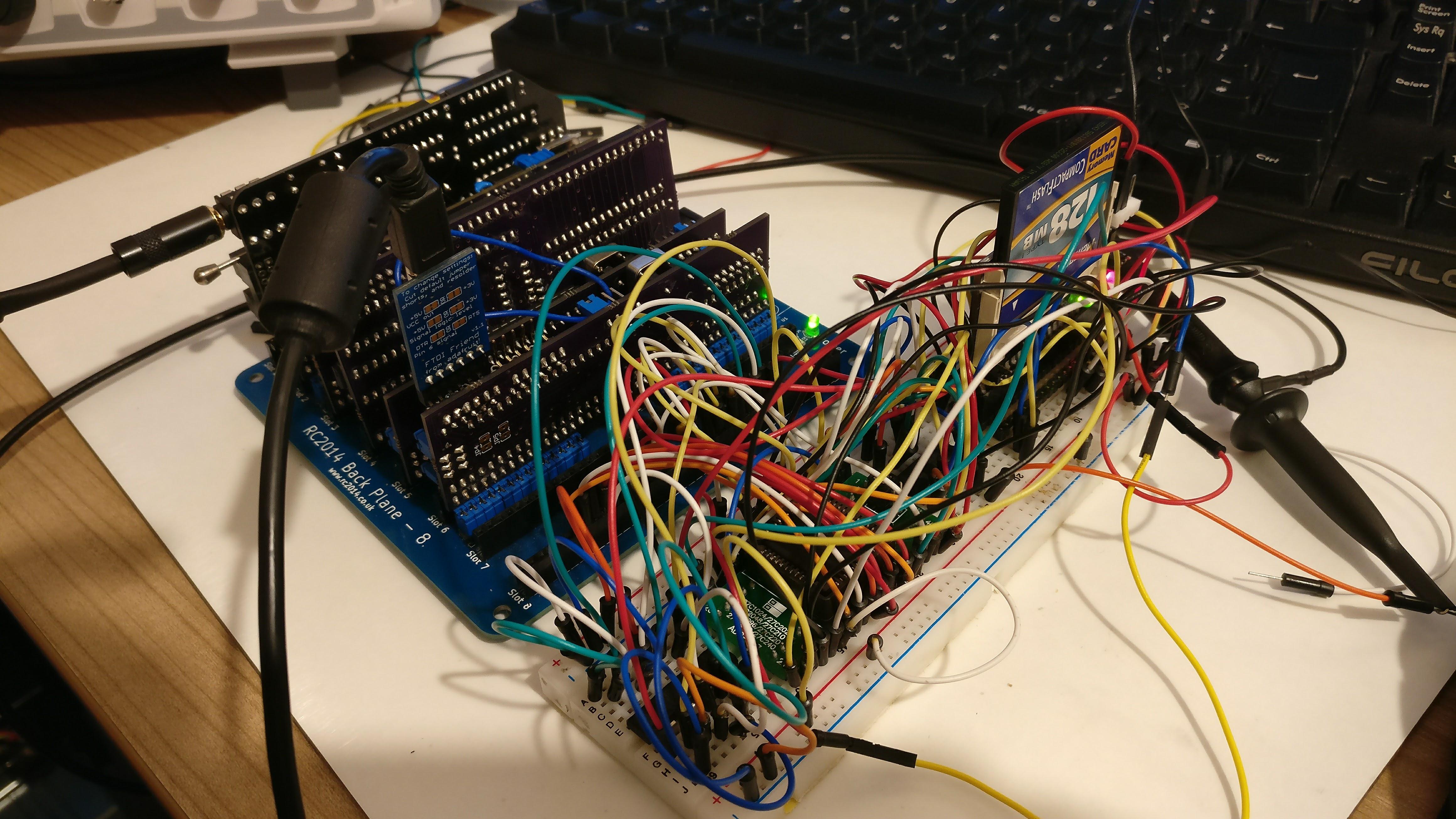
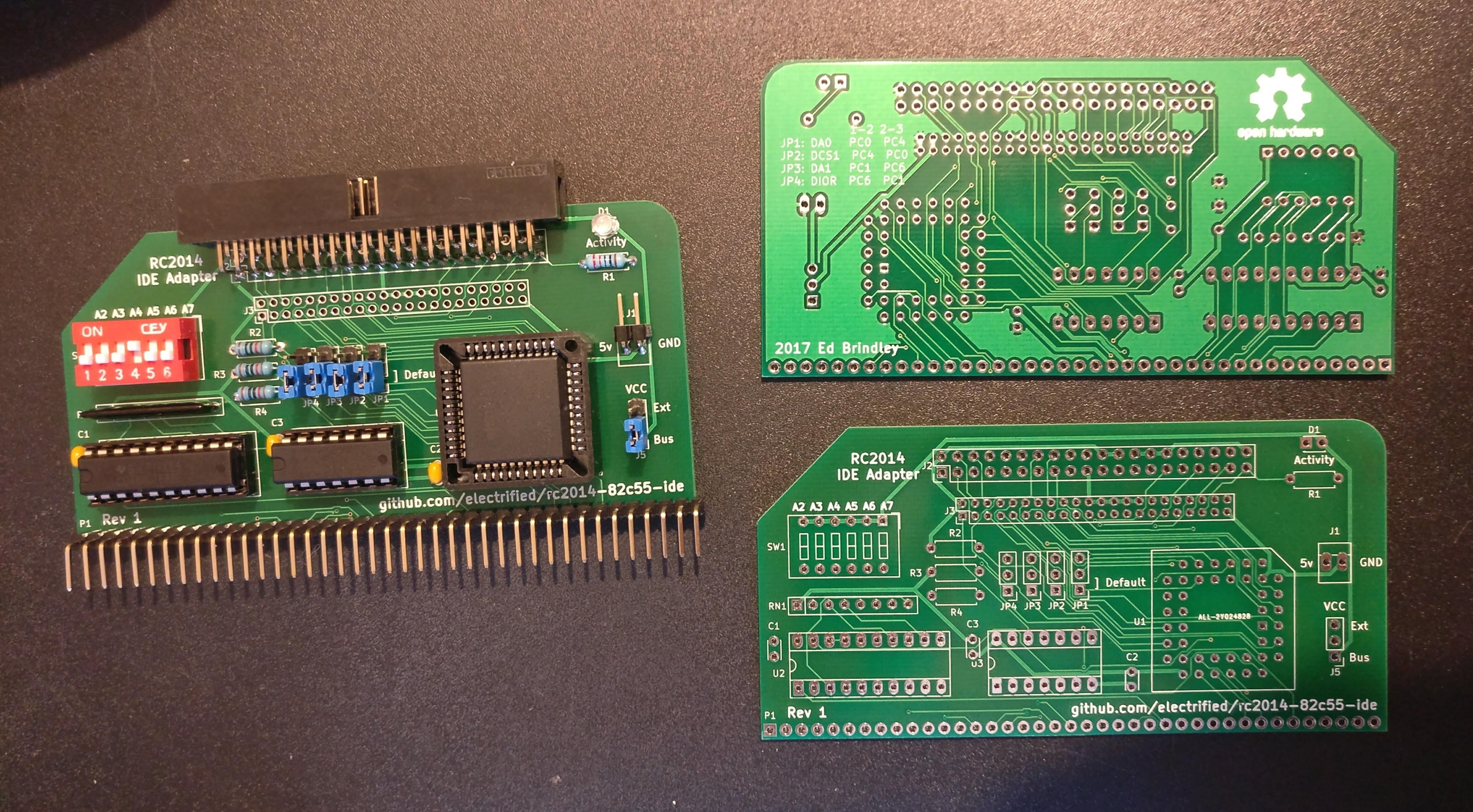
Got my PCBs back and they work, which is a relief!
See attached picture :) I've not got the connectors for the 2.5" drive yet, could only find them on eBay from China, so may be a while.
Re I/O port, I've been running mine at 0x20, but that was a fairly arbitrary pick (what I was previously running my CF adapter at)
Cheers,
Ed
PianoMatt
Sep 29, 2017, 3:43:14 PM9/29/17
to RC2014-Z80
Hi Ed
What config have you used to get yours going? I've used the following, but I wasn;t sure about the 8-bit option
What config have you used to get yours going? I've used the following, but I wasn;t sure about the 8-bit option
PPIDEENABLE     .EQU    TRUE
PPIDEMODE       .EQU    PPIDEMODE_DIO3
PPIDETRACE      .EQU    1
PPIDE8BIT .EQU FALSE 
David Hardingham
Sep 29, 2017, 4:09:35 PM9/29/17
to RC2014-Z80
Well done Ed.
PianoMatt
Sep 29, 2017, 4:39:37 PM9/29/17
to RC2014-Z80

Ed Brindley
Sep 29, 2017, 5:59:09 PM9/29/17
to RC2014-Z80
Hi Matt,
Yep I'm using the same config.
Yep I'm using the same config.
PianoMatt
Sep 29, 2017, 6:09:53 PM9/29/17
to RC2014-Z80
I'm slightly disappointed that it worked first time. I've lost out on hours of valuable troubleshooting. I didn't even need my meter let alone my scope!

Spencer Owen
Sep 29, 2017, 6:22:25 PM9/29/17
to rc201...@googlegroups.com
Unfortunately this is becoming an intrinsic part of the RC2014 ecosystem.
There seem to be many many people getting their RC2014 and assembling it without going through the troubleshooting experience :-( Some RC2014 users don't use a multimeter, let alone a scope.
It's a sad sad day when people can buy a board, put it together and enjoy its goodness without need of a few probes. When I were lad, we went down the Python Yorkshiremen Sketch route, crafting packets by hand at 300 baud 24/7. But, tell that to the youngens today and will they believe you? Will'es by eck!
:-D
Spencer
On 29 Sep 2017 23:09, "PianoMatt" <mattyb...@gmail.com> wrote:
I'm slightly disappointed that it worked first time. I've lost out on hours of valuable troubleshooting. I didn't even need my meter let alone my scope!
--
You received this message because you are subscribed to the Google Groups "RC2014-Z80" group.
To unsubscribe from this group and stop receiving emails from it, send an email to rc2014-z80+unsubscribe@googlegroups.com.
To post to this group, send email to rc201...@googlegroups.com.
To view this discussion on the web, visit https://groups.google.com/d/msgid/rc2014-z80/d204cfeb-8a09-44e2-9f99-214aa6fd0f3b%40googlegroups.com.
For more options, visit https://groups.google.com/d/optout.
PianoMatt
Sep 29, 2017, 6:28:40 PM9/29/17
to RC2014-Z80
Maybe we need to up the difficulty curve. I did consider switching to SMD components for the ADC board I made, but I figured that it would be pretty cruel, and far too modern.
On Friday, 29 September 2017 23:22:25 UTC+1, Spencer Owen wrote:
Unfortunately this is becoming an intrinsic part of the RC2014 ecosystem.There seem to be many many people getting their RC2014 and assembling it without going through the troubleshooting experience :-( Some RC2014 users don't use a multimeter, let alone a scope.It's a sad sad day when people can buy a board, put it together and enjoy its goodness without need of a few probes. When I were lad, we went down the Python Yorkshiremen Sketch route, crafting packets by hand at 300 baud 24/7. But, tell that to the youngens today and will they believe you? Will'es by eck!:-DSpencer
Spencer Owen
Sep 29, 2017, 6:37:17 PM9/29/17
to rc201...@googlegroups.com
Either that, or make valves an integral component. With had drawn schematics using unique symbols that only pre-war engineers understood.
Spencer - feeling guilty for derailing the thread and taking the focus away from Ed's awesome board.
To view this discussion on the web, visit https://groups.google.com/d/msgid/rc2014-z80/87f69867-dc01-442f-bb46-912a67b40eea%40googlegroups.com.

Peter Fielden-Weston
Sep 29, 2017, 7:47:26 PM9/29/17
to RC2014-Z80
No, valves take too much power. Use individual transistors instead.
P
P
phillip.stevens
Sep 29, 2017, 8:40:06 PM9/29/17
to RC2014-Z80
Ed,
Got my PCBs back and they work, which is a relief!
looks great. Can't wait to get one too.
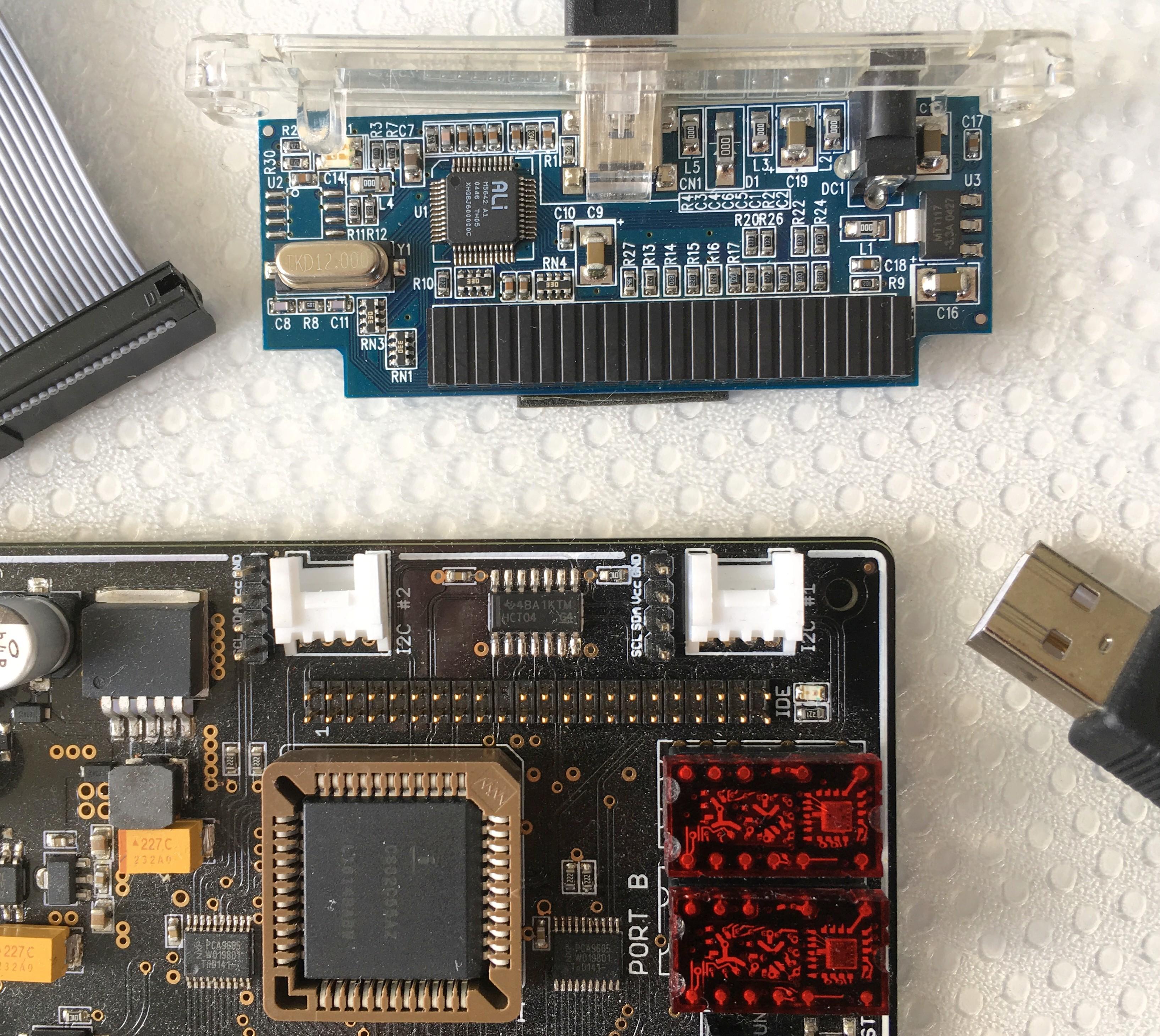
See attached picture :) I've not got the connectors for the 2.5" drive yet, could only find them on eBay from China, so may be a while.
I used a Molex connector from Digikey. At least you wouldn't be caught up in the National Day holiday for shipping from China.
Attached a picture showing the connector, and showing the insides of the old USB external drive that I use to check the IDE drive is working and move files around.
Re I/O port, I've been running mine at 0x20, but that was a fairly arbitrary pick (what I was previously running my CF adapter at)
And thus it was "the Standard". :-)
All you have to do to get diskio and therefore FatFs running is change the base address to 0x20, and everything should just work (to the extent I could test it without identical hardware). You can move this base address anytime, and then simply do a
cd ~/libsrc/_DEVELOPMENT
make job-rc2014
to avoid having to compile the whole of z88dk every time you make a configuration change.
On Friday, 29 September 2017 13:50:45 UTC+1, PianoMatt wrote:The base address could be defined at compile time couldn't it? Would make more sense since there are so many different systems that could use this implementation.
The base address IS defined at compile time, in this config_target.m4 file. There is a manual backup file kept too.
The config_*.m4 files are are used as a single source of truth to generate a set of target specific assembly includes and C header files that are used throughout the z88dk target builds.
Cheers, Phillip

Eric Matecki
Sep 30, 2017, 11:27:45 AM9/30/17
to RC2014-Z80
Has already been done, its called the megaprocessor :
If you want to know how the technology used in the RC2014 is just the right one for DIY, look at the cost page of the Mega...

Stephen Kelly
Sep 30, 2017, 1:55:45 PM9/30/17
to RC2014-Z80
Nice one, Ed and Matt.
Will either of be making you boards available as Gerbers or for sale?
I would quite like to build a few of these!
I already have a couple of CMP82C55AZ in DIP40, so I'm slightly drawn to Matt's design for reasons of parsimony only.
Somehow, floppy drives and CF just don't seem to be enough for my RC2014's any more. :)
Cheers,
Stephen
PianoMatt
Sep 30, 2017, 2:37:46 PM9/30/17
to RC2014-Z80
Hi Stephen
I've put the gerbers, schematic and BOM on Github. If you want one of the boards I'm selling them £5 including shipping.
https://github.com/mattybigback/RC2014/tree/master/Boards/PPIDE
I've put the gerbers, schematic and BOM on Github. If you want one of the boards I'm selling them £5 including shipping.
https://github.com/mattybigback/RC2014/tree/master/Boards/PPIDE
Stephen Kelly
Sep 30, 2017, 3:34:32 PM9/30/17
to RC2014-Z80
Thanks, Matt.
I'll have two, please.
A tenner on it's way via Paypal!
Cheers,
Stephen
Eric Matecki
Sep 30, 2017, 3:35:39 PM9/30/17
to RC2014-Z80
Hi Matt,
(This will round out my Mouser order with the ADC parts)
Thank you.
Thank you.
Ed Brindley
Sep 30, 2017, 7:05:00 PM9/30/17
to RC2014-Z80
Hi,
Yep I also have spare boards of my PLCC44 version if anyone wants one.
Cheers,
Ed
Yep I also have spare boards of my PLCC44 version if anyone wants one.
Cheers,
Ed

Jan S
Oct 1, 2017, 2:55:10 AM10/1/17
to RC2014-Z80
Hi Ed
I would like to grap one. How do we proceed from here :-)
/Jan
I would like to grap one. How do we proceed from here :-)
/Jan
Stephen Kelly
Oct 1, 2017, 6:13:10 AM10/1/17
to RC2014-Z80
Hello Ed,
I would be interested in taking a couple, if you have enough to spare.
Please let me know how much and how you would like payment.
Cheers,
Stephen
Ed Brindley
Oct 1, 2017, 6:21:04 AM10/1/17
to RC2014-Z80
Hi Jan (and others!),
Cost is £5 + a bit more for international postage if needed, via PayPal.
I'll drop you an email.
Thanks,
Ed
Cost is £5 + a bit more for international postage if needed, via PayPal.
I'll drop you an email.
Thanks,
Ed
Ed Brindley
Oct 1, 2017, 9:30:43 AM10/1/17
to RC2014-Z80
Finally got round to pushing my repo up to GitHub: https://github.com/electrified/rc2014-82c55-ide
Kicad project, gerbers and the BOM.
Let me know if there's anything missing!
Cheers,
Ed
Kicad project, gerbers and the BOM.
Let me know if there's anything missing!
Cheers,
Ed
PianoMatt
Oct 3, 2017, 1:31:45 PM10/3/17
to RC2014-Z80
Here's my repo too. I've included a PDF schematic and the readme has a bit about changing the code to support different base IO addresses
https://github.com/mattybigback/RC2014/tree/master/Boards/PPIDE
https://github.com/mattybigback/RC2014/tree/master/Boards/PPIDE
PianoMatt
Oct 3, 2017, 2:31:07 PM10/3/17
to RC2014-Z80
Ed, I just noticed something in your repo in the bit about setting DIP switches. Shouldn't it be A5 that is on, and not A6?
Ed Brindley
Oct 3, 2017, 4:21:17 PM10/3/17
to RC2014-Z80
Good spot, thanks
Eric Matecki
Oct 14, 2017, 1:13:18 PM10/14/17
to RC2014-Z80
Hi Spencer,
time to update the "3rd party modules" page I guess :)
Two IDE boards plus Matt's ADC board (at least, I may have missed the one or the other...)
Spencer Owen
Oct 16, 2017, 10:20:02 AM10/16/17
to rc201...@googlegroups.com
Thanks, Eric,
Yes, the 3rd Party Modules page is due an update. Should be soon :-)
Cheers
Spencer
--
You received this message because you are subscribed to the Google Groups "RC2014-Z80" group.
To unsubscribe from this group and stop receiving emails from it, send an email to rc2014-z80+unsubscribe@googlegroups.com.
To post to this group, send email to rc201...@googlegroups.com.
To view this discussion on the web, visit https://groups.google.com/d/msgid/rc2014-z80/4c251d39-5f15-431d-9161-0578bcde9bb4%40googlegroups.com.
Ed Brindley
Oct 23, 2017, 6:17:10 PM10/23/17
to RC2014-Z80
If anyone's still after an IDE board, I've bunged a few more up on Tindie.
https://www.tindie.com/products/edbrindley/ide-adapter-pcb-for-the-rc2014-computer/
Cheers,
Ed
https://www.tindie.com/products/edbrindley/ide-adapter-pcb-for-the-rc2014-computer/
Cheers,
Ed
Ed Brindley
Nov 26, 2017, 1:23:56 PM11/26/17
to RC2014-Z80

Steve Cousins
Nov 27, 2017, 5:24:33 PM11/27/17
to RC2014-Z80
Nice video Ed.
Very impressive set up.
I'm new here and have some serious catching up to do!
Steve
Ed Brindley
Jan 2, 2018, 10:03:50 AM1/2/18
to RC2014-Z80
I've updated the README to recommend using Wayne's mainline version of RomWBW now RC2014 support has been incorporated.
https://github.com/electrified/rc2014-82c55-ide
Cheers,
Ed
https://github.com/electrified/rc2014-82c55-ide
Cheers,
Ed
phillip.stevens
Jan 31, 2018, 11:38:28 PM1/31/18
to RC2014-Z80
Time for another update on the FatFS progress.
It has been a few months since I've written on this topic. I've been busy working on details, and Christmas / New Year caused a bit of down time too.
The new net FatFS read or write rate is just under 300kB/s, which is barely different to the underlying assembly code for diskio.
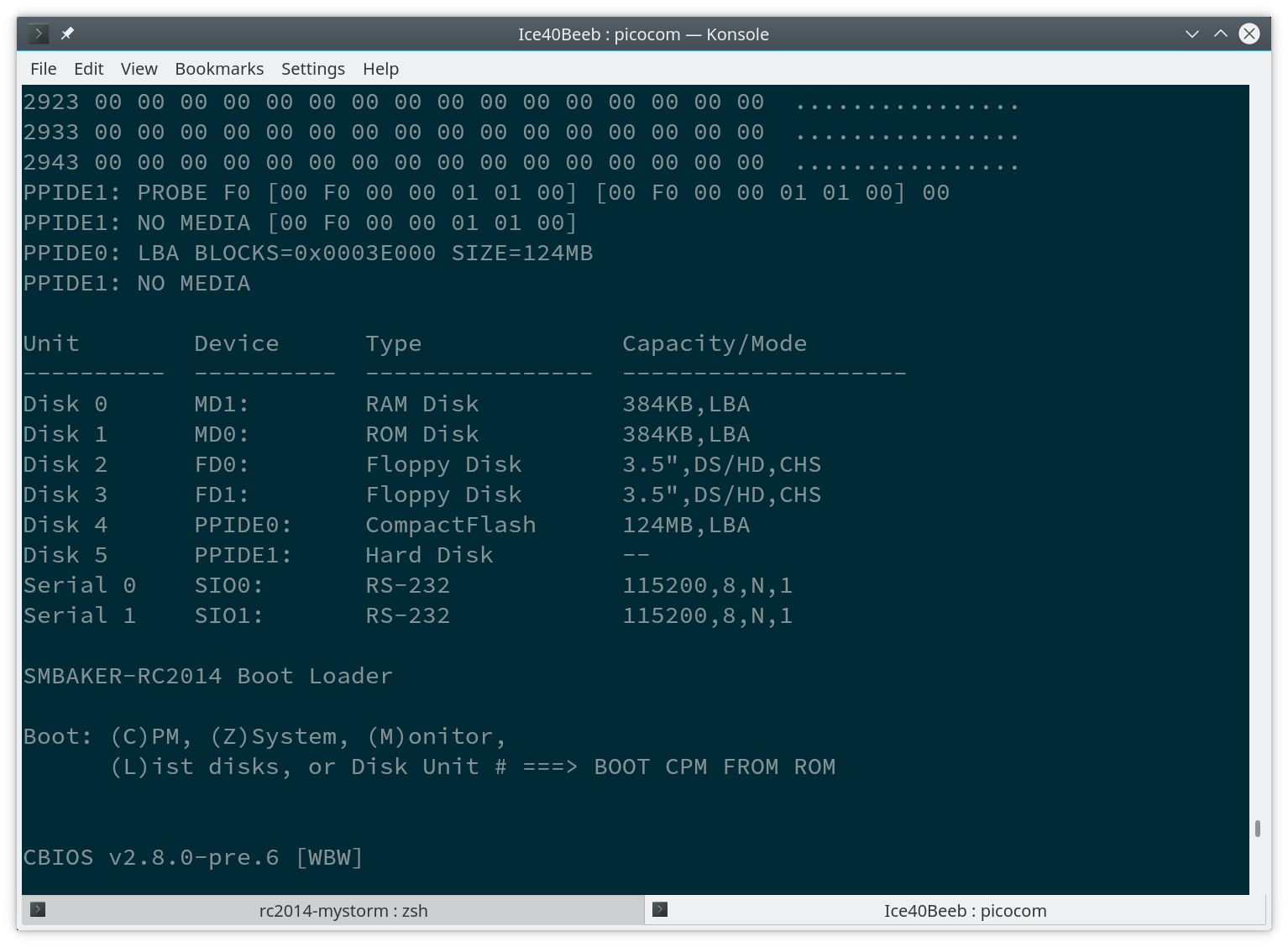
Anyway, I thought that it might be a good time to put a few notes together about my experience of getting CP/M to run off an IDE drive, which is formatted with FAT32 file system.
The TL;DR of this story is that it is possible (even easy) to use an IDE drive with FAT32 formatting together with CP/M, and that in doing this the cpmtools can be used to write com files directly from a Linux (and other) PC directly to the CP/M drive image file, and therefore make special disk "loading" tools unnecessary.
As background, most (all) of the implementations of CP/M on IDE that I've seen take shortcuts with the decoding of the IDE Logical Block Address, which means that the CP/M drive is composed of non-contiguous sector data on the drive. Often either only 8 bits of the 16 bit IDE interface is used, or the CP/M sector, track and disk characteristics are laid out so that the data is spread across various sectors in the drive, making it impossible to read the data as a normal FAT32 drive.
The main result I've achieved is writing a LBA translation routine that can take a specific CP/M format, and convert it to contiguous sectors on the IDE drive, which is within the bounds of a FAT32 file. This makes it possible for the cpmtools to read and write data directly when the drive is installed on a host PC system.
What are the limitations?
- You have to know the base LBA of the image file (or CP/M drive). I calculate this information and store it in the Page 0 scratch area from 0x0040 to 0x004F for up to 4 files, when I'm preparing to boot CP/M.
- The file system and the bios have to match, because CP/M relies on fixed formats. I have chosen to have 32 sectors per track, and up to 2048 tracks per disk. More on the reasons why below. This totals then 32MByte per disk, using 4096 byte blocks, with a maximum of 4 disks in my system. I also elected to use 512 directory extents (or file indexes) per drive.
- I have to use 32 sectors per track because the "standard" deblocking routine will overflow uint8_t comparison if I use any greater than this (and is a binary multiple). Non-binary sectors per track makes the LBA calculation awkward and slow. 32 sectors can be stored in 5 bits.
- The maximum tracks per disk is set at 2048 because this can be stored in 11 bits, and together with the sector calculation results in 16 bits of LBA offset from the base LBA. More could be supported, if required, but doing this would impact the RAM available to the CP/M system.
- It uses the underlying diskio ide_read_sector and ide_write_sector functions that I wrote to support the ChaN FatFS code previously. These functions are written to be fast and don't have any error checking (assuming modern IDE drives work most of the time anyway). The base LBA for the file can be found using the Chan tools, and this is used to direct the low level IDE I/O functions to the right sector by LBA.
How does it work?
Well IMHO, it works well. CP/M COM files can be stored directly from a PC, and can be read and written from the CP/M system. And, it is fast.
That's all that matters. Getting files on the CP/M system is as simple as copying them on the host PC. The reverse is also true.
I haven't pushed this to RC2014 yet. But, it won't be hard to do so, and use Ed's 8255 IDE interface to drive this.
The usage works like this. To check the disk image on the host platform,
ls a CP/M image, copy a file (in this case bbcbasic.com).> fsed.cpm -f yaz180-16MB a.cpm > cpmls -f yaz180-16MB a.cpm > cpmcp -f yaz180-16MB a.cpm ~/Desktop/CPM/bbcbasic.com 0:BBCBASIC.COM
The contents of the /etc/cpmtools/diskdefs file need to be updated to include the specific to the file format calculations I've used.
diskdef yaz180-32MB
seclen 512
tracks 2048
sectrk 32
blocksize 4096
maxdir 512
skew 0
boottrk -
os 2.2
end
diskdef yaz180-16MB
seclen 512
tracks 1024
sectrk 32
blocksize 4096
maxdir 512
skew 0
boottrk -
os 2.2
end
diskdef yaz180-8MB
seclen 512
tracks 512
sectrk 32
blocksize 4096
maxdir 512
skew 0
boottrk -
os 2.2
endphillip.stevens
Feb 1, 2018, 5:09:55 AM2/1/18
to RC2014-Z80
Time for another update on the FatFS progress.It has been a few months since I've written on this topic. I've been busy working on details, and Christmas / New Year caused a bit of down time too.The new net FatFS read or write rate is just under 300kB/s, which is barely different to the underlying assembly code for diskio.Anyway, I thought that it might be a good time to put a few notes together about my experience of getting CP/M to run off an IDE drive, which is formatted with FAT32 file system.The TL;DR of this story is that it is possible (even easy) to use an IDE drive with FAT32 formatting together with CP/M, and that in doing this the cpmtools can be used to write com files directly from a Linux (and other) PC directly to the CP/M drive image file, and therefore make special disk "loading" tools unnecessary.As background, most (all) of the implementations of CP/M on IDE that I've seen take shortcuts with the decoding of the IDE Logical Block Address, which means that the CP/M drive is composed of non-contiguous sector data on the drive. Often either only 8 bits of the 16 bit IDE interface is used, or the CP/M sector, track and disk characteristics are laid out so that the data is spread across various sectors in the drive, making it impossible to read the data as a normal FAT32 drive.The main result I've achieved is writing a LBA translation routine that can take a specific CP/M format, and convert it to contiguous sectors on the IDE drive, which is within the bounds of a FAT32 file. This makes it possible for the cpmtools to read and write data directly when the drive is installed on a host PC system.
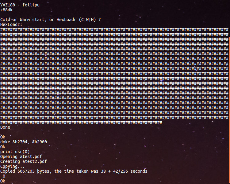
How does it work?Well IMHO, it works well. CP/M COM files can be stored directly from a PC, and can be read and written from the CP/M system. And, it is fast.That's all that matters. Getting files on the CP/M system is as simple as copying them on the host PC. The reverse is also true.I haven't pushed this to RC2014 yet. But, it won't be hard to do so, and use Ed's 8255 IDE interface to drive this.The usage works like this. To check the disk image on the host platform,lsa CP/M image, copy a file (in this casebbcbasic.com).
> fsed.cpm -f yaz180-16MB a.cpm
> cpmls -f yaz180-16MB a.cpm
> cpmcp -f yaz180-16MB a.cpm ~/Desktop/CPM/bbcbasic.com 0:BBCBASIC.COM
A picture of how it looks is worth adding.

Ed Brindley
Feb 1, 2018, 8:39:56 AM2/1/18
to RC2014-Z80
Hi Phillip,
Great work on this!
A few questions:
Would it be theoretically possible to integrate this with the RomWBW BIOS?
Does it handle the file on the FAT32 filesystem potentially being fragmented?
Cheers,
Ed
Phillip Stevens
Feb 1, 2018, 4:38:41 PM2/1/18
to rc201...@googlegroups.com
Hi Ed,
Thanks.
It was a real learning experience about the detailed internals of CP/M. So very worthwhile doing.
But now it is done, I'm happy just to play Zork for a few weeks.
Before I move on to other spot fires...
A few questions:Would it be theoretically possible to integrate this with the RomWBW BIOS?
Yes, absolutely. In fact it is probably nearly integrated already. At least all the pieces are there in exactly the same fashion.
Some of the diskio stuff in RomWBW is more complicated, because it has to deal with floppy drive sector skewing, and drive errors, etc.
But the same "standard" deblocking algorithm is used, I believe, and the IDE drivers are quite similar (but with better error handling = slower).
I think the only minor difference is the actual LBA calculation routine, balanced against the strict CP/M disk format requirements, to ensure that the data is written to disk contiguously.
RomWBW evaluates the capacity of the disk, and uses this to calculate its disk access parameters. And, I don't think there is any attempt to ensure that the data written can co-exist with another file format. This could easily be checked by someone who understands the complexity of all of the RomWBW cbios or hbios options.
Does it handle the file on the FAT32 file system potentially being fragmented?
No, I don't handle fragmentation.
The address calculation is simply to use the base LBA for the file, and then use an offset from that base LBA to access each sector in turn.
The base LBA is obtained either when the "drive" file is created, or when it is opened.
In fact, it is essential to create the "drive" file using contiguous sectors, and there is a ChaN FatFS f_expand() function for that. I use the f_expand() function when creating the drive file on the z80 platform to ensure that the space allocated is contiguous.
I updated the z88dk-libraries RC2014 build of FatFS to add this f_expand() function specifically for this purpose. The cpm tools fsck.cpm doesn't provide this extend() function, so the "drives" it generates are not full size on creation, and therefore are potentially not going to be contiguous as they grow. So it is actually better to create the CP/M drive file using z80 ChaN functions, than it is using the PC cpm tools.
The end result is a bit of a layer-cake of code, that is located in different places.
Here are all the pieces for future reference.
A linux / windows cpmtools toolset that allows data on a CP/M drive image within a FatFS drive to be written and read, when the drive is mounted on the PC.
A CP/M bios, that uses the base LBA references located at 0x0040 to 0x004F to access contiguous data found within (4x) FatFS filex as (4x) CP/M drive.
A z88dk C code monitor that can create CP/M drive files, and prepares the LBA references for CP/M.
z88dk IDE and 8255 device driver interfaces.
And your 8255 IDE interface hardware.
Cheers, Phillip
Reply all
Reply to author
Forward
0 new messages