Re: Changing out the stepper drivers- experimentation results
255 views
Skip to first unread message
Message has been deleted

Charles Tsang
Feb 7, 2016, 9:16:20 AM2/7/16
to Raise3D
thanks for the link, just ordered them. Any recommendation for a quieter fan? I wouldn't even mind modifying the cover of the electrical box to make it fit. I'm coming from an ancient Thingomatic that is almost completely silent when it is idle. Thanks
On Sunday, February 7, 2016 at 2:52:35 AM UTC-6, Jetguy wrote:
On Sunday, February 7, 2016 at 2:52:35 AM UTC-6, Jetguy wrote:
I posted in the other early review thread in the tips and tricks group about changing the X and Y stepper drivers to Panucatt SD6128s since they are the latest chip and 100% compatible socket and electrical wise (inverted enabled signal) VS the stock A4988s and the TMC2100s.I agree now with the Raise 3D team, the TMC2100s are noticeably quieter than any driver I threw at this . I tested them side by side.One thing I did was add tiny stick on heatsink to the bottom side of the driver to further assist in heat reduction. Not required but I say you can never go too far on cooling.These specific tiny heatsinks http://www.amazon.com/gp/product/B007XACV8O
Message has been deleted
Message has been deleted
Message has been deleted
Charles Tsang
Feb 7, 2016, 4:34:59 PM2/7/16
to Raise3D
cool! I'll have to find all your other post with digikey parts so I can order them at the same time. thanks!
On Sunday, February 7, 2016 at 9:27:53 AM UTC-6, Jetguy wrote:
On Sunday, February 7, 2016 at 9:27:53 AM UTC-6, Jetguy wrote:
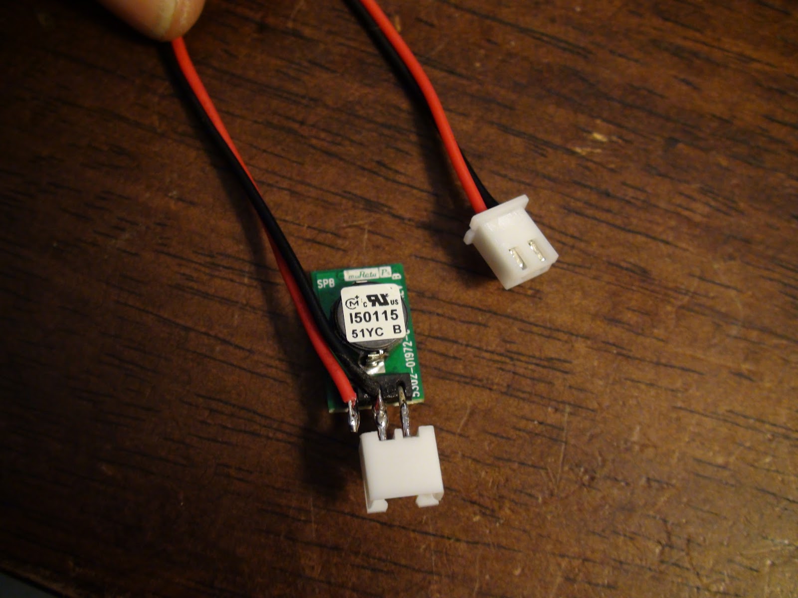
Do not replace the stock blower. The easiest mod ever, simply run it on 5V. It blows NICELY and QUIETLY on 5V.
In theory it's a 0.4A rated fan,so you might be able to connect to the 5V regulated onboard the motion controller board (based on RUMBA) however, a brushless fan does make electrical noise not to mention the load on the regulator.
I had some of the spare connectors handy from other projects and whipped this out in 10 minutes.
I love these 5V 3 pin regulators that can take up to 36V in and output up to 1A of 5V.
https://www.digikey.com/product-detail/en/OKI-78SR-5%2F1.5-W36-C/811-2196-5-ND/2259781
They are just amazing little devices.
It's just an inline regulator for the fan.
And with heatshrink installed


Derek@Raise3D
Feb 8, 2016, 8:25:03 PM2/8/16
to Raise3D
I see that. 5V is enough for PLA. But still need some more wind for closed chamber ABS printing.
在 2016年2月7日星期日 UTC+8下午11:30:50,Jetguy写道:
在 2016年2月7日星期日 UTC+8下午11:30:50,Jetguy写道:
Again, that is a great blower. It's ball bearing and top quality. it should last a really long time.
All we needed to do was lower the power and 5V seemed to be perfect in my testing.
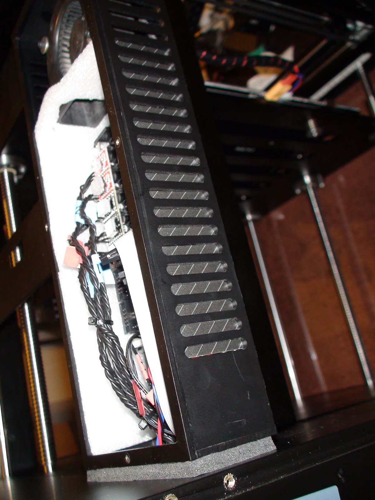
Then I went onto the cold ducting to prevent recirculating the same old hot air in the box.
In the shipping material was some thin foam sheets I cut to make the divider.

On Sunday, February 7, 2016 at 10:27:53 AM UTC-5, Jetguy wrote:
Do not replace the stock blower. The easiest mod ever, simply run it on 5V. It blows NICELY and QUIETLY on 5V.
In theory it's a 0.4A rated fan,so you might be able to connect to the 5V regulated onboard the motion controller board (based on RUMBA) however, a brushless fan does make electrical noise not to mention the load on the regulator.
I had some of the spare connectors handy from other projects and whipped this out in 10 minutes.
I love these 5V 3 pin regulators that can take up to 36V in and output up to 1A of 5V.
https://www.digikey.com/product-detail/en/OKI-78SR-5%2F1.5-W36-C/811-2196-5-ND/2259781
They are just amazing little devices.
It's just an inline regulator for the fan.
And with heatshrink installed
On Sunday, February 7, 2016 at 9:16:20 AM UTC-5, Charles Tsang wrote:
Charles Tsang
Feb 8, 2016, 9:05:45 PM2/8/16
to Raise3D
Why not just move the electronics out of the case? Then it wouldn't be an issue.
Message has been deleted
Message has been deleted
Message has been deleted
Charles Tsang
Feb 8, 2016, 9:44:16 PM2/8/16
to Raise3D
How about just moving the "outside" to the "inside." We could put a plate right over the two horizontal rails that holds the filament rolls. This will now be the "outside" of the printer. Of course, we would also have to use foam to block other places that lets air into the "inside" of the printer. (just like what you outlined above) Then block the lower few inches of the vents in the electronics box. Air would still come in from the outside and exit through the bottom. We can then just remove the side door completely.
For me, the benefit of this would be 1) not having to cut a vent hole in the back, 2) having more room to put thicker rolls of filament.
On Monday, February 8, 2016 at 8:17:09 PM UTC-6, Jetguy wrote:
For me, the benefit of this would be 1) not having to cut a vent hole in the back, 2) having more room to put thicker rolls of filament.
On Monday, February 8, 2016 at 8:17:09 PM UTC-6, Jetguy wrote:
Which goes to to the second modification, changing the duct so that cold fresh outside air is taken in from the back of the machine.
I have not yet cut the back panel because they are Polycarbonate??? Not acrylic right? With my laser cutter, poly makes horrible fumes.
Please say what plastic the acrylic panels are made from. I think they are router cut because of this.
It's 4 parts.
#1 make a divider to clearly separate the intake of the blower from the rest of the electronics box.
Also notice the front facing vents to the inside of the printer are blocked.
#2 Block off the vents so the air is forced passed the electronics and out the bottom hole with the wires.
I just used the packing foam because it was handy. I later found some back cardboard and used that to make it nicer.
#3 Cut a matching set of intake vents in the clear plastic panel, then use foam strip to seal the electronics back intake to the now cut through fresh air intake at the rear of the printer.
I haven't yet done this awaiting to find out what plastic the clear panels are made from.
#4 A panel is made to force the incoming exhaust from the control box to the base, then directed through the large gap in the corner of the lower box frames.
Not a great shot but the same black window and door sealer foam (looks grey in this photo with the flash ) tape to the base.
Also, you can see the black card stock blocking the vents (also looking grey under flash)
Finally, under the printer, the corner was not covered by the existing panel.
A small panel also prevents the air from shooting down the outside of the lower frame rail.
Advantages of this system:
#1 Quiet and no need for fast and loud fan.
#2 Fresh cold room air feeds the electronics at all times.
#3 That same fresh air is not polluting the warm controlled chamber for ABS printing.
#4 Now, cool fresh air is also forced into the base of the printer and aids in cooling the main PSU.


Derek@Raise3D
Feb 11, 2016, 11:15:00 PM2/11/16
to Raise3D
Jesus, I missed a whole Manhattan project here. Just go back to office, start to work tomorrow.
The whole transparent chamber cover is Polycarbonate. The top cover is acrylic.
And you are taking air from the down side right? That's just in my mind too.
在 2016年2月9日星期二 UTC+8上午10:17:09,Jetguy写道:
在 2016年2月9日星期二 UTC+8上午10:17:09,Jetguy写道:
Message has been deleted
Charles Tsang
Feb 12, 2016, 4:52:23 PM2/12/16
to Raise3D
What did you use to cut that vent? Looks very good. Did you take the panel off to cut it or did you cut it in place? thanks!
On Friday, February 12, 2016 at 4:50:18 AM UTC-6, Jetguy wrote:
On Friday, February 12, 2016 at 4:50:18 AM UTC-6, Jetguy wrote:
The foam window tape looks white/grey under flash in the photo but actually is nearer to black/grey in real life.
All vents are blocked on the control box except the intake now at the upper rear.
In the picture, I found some black colored cardboard with some angled pinstripes to cover the vents inside the box.


Reply all
Reply to author
Forward
Message has been deleted
0 new messages