Radioberry QRP
1,614 views
Skip to first unread message

pa3gsb
Feb 14, 2021, 6:42:26 AM2/14/21
to Radioberry
Radioberry preamp board.
This board is a nice addition to turn the radioberry into a small QRP radio.
The design is based on all the amazing work of Hermes Lite 2 Group!
Some specs:
Power in : 12V
HF Power in : Tx from radioberry.
HF Power out: 5W
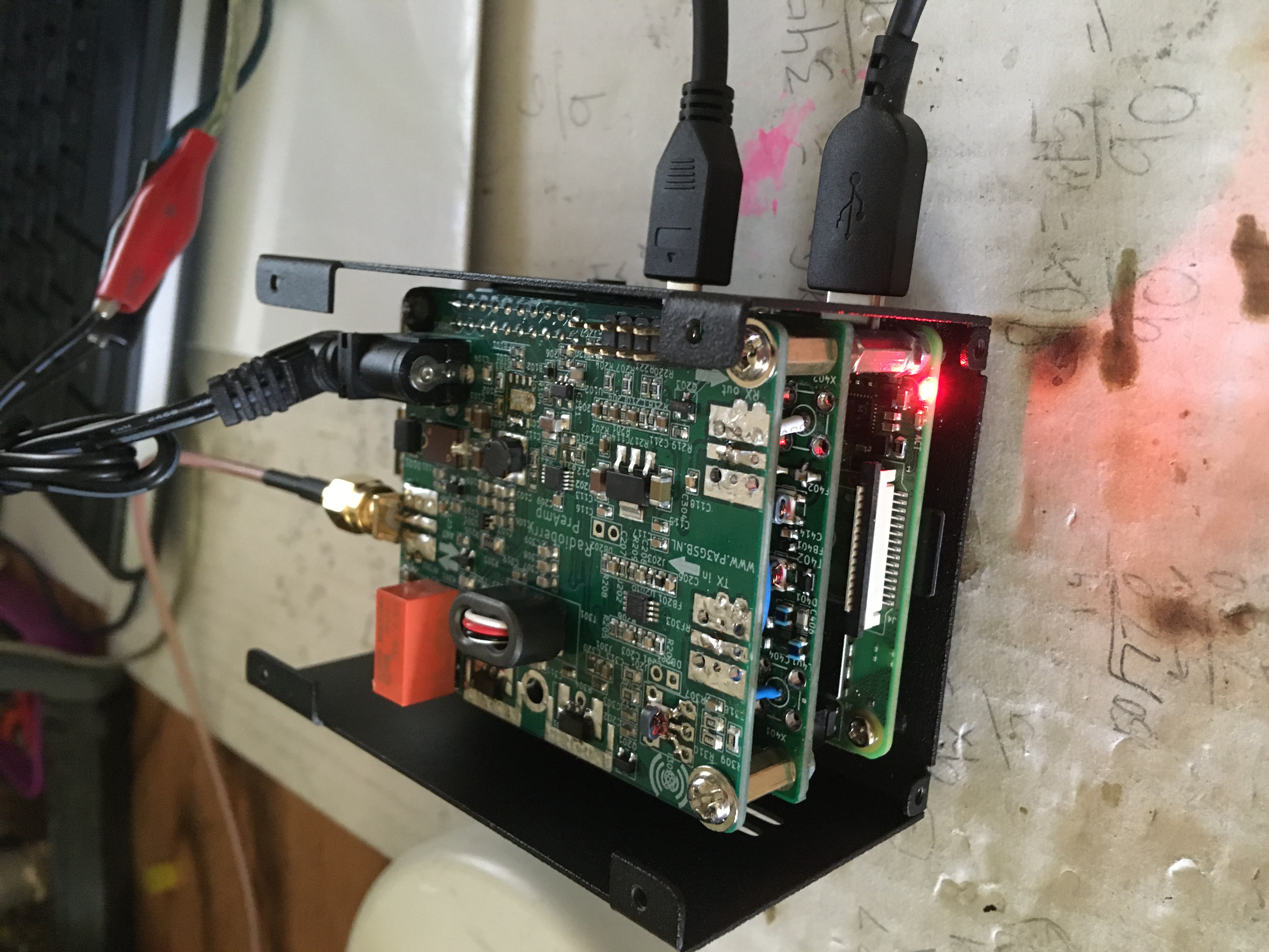
The board (2-layers) must be plugged on top of the radioberry.
External connections:
IN:
- KEY
- PTT
- DASH/DOT for CW using pihpsdr.
OUT:
- External PTT
RX/TX Switching is done using a relais.
I do use this board with my power amplifier (100 W) using built in LPF filters.
The board contains 2 fets for getting the HF power.
Furthermore the board contains two i2c sensor devices.
MCP4662 Dual digital potentiometer.
This device is used to set both bias settings for the Radioberry preAmp.
The setting can be made permanent (non volatile) by saving the bias values in the EEPROM of the device.
The bias is a specific setting stored and determined specific per preAmp board. (Setup only once).
MAX11613 4 Channel Slow ADC
This device is measuring:
- the temperature of the PA finals
- the PA current during transmit.
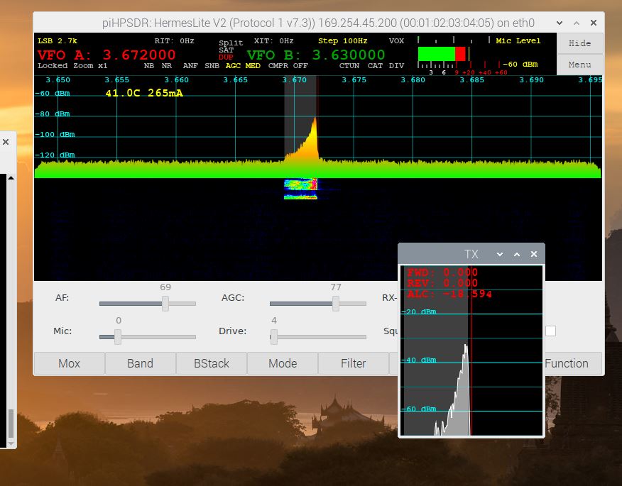
The temperature and current are visible in the SDR program.
Control the PA by gateware and firmware:
- the bias voltage and power supply (swith the PA on/off)
- switch off the attached power amplifier if the current and temp could not be measured.
- supports the setting of the pa bias setting
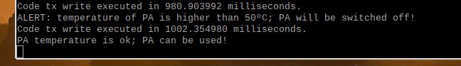
- if temperature of PA is higher than 50C; PA will be switched off!
- PA recovery after high temperature; switch PA on again if PA temp is in range for 10 seconds.
RPI setting:
The control of the i2c devices is not done by the gateware as done in the HL-2 but in the firmware
by use of the i2c module running on the RPI, so the i2c module must be selected.
Connecting the board (12V is not required to connect) and by opening a command window
it is possible to detect the attached devices: sudo i2cdetect -y 1
Radioberry Software Changes:
To support the board I have changed the gateware, firmware and device driver. Need to update github and make a release.
Update of wiki is also required.
I have some assembled boards available please let me know if you are interested?
Have fun
73 Johan
PA3GSB
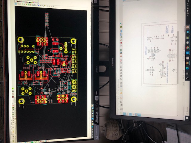
Pictures:
development process... sometimes hard for someone who is colorblind....
.jpg?part=0.5&view=1)
.jpg?part=0.2&view=1)
PA protection.... also visible in the log!

Luca
Apr 2, 2021, 1:06:40 PM4/2/21
to Radioberry
Hi Johan,
Congratulations for your beautiful board.
i have just ordered PCB, fro JLPCB.
For your opinion which is the best solution for mechanical connect the board ? I it will be stacked maybe there is no enough space for heat dissipators.
Con you please share your current solution?
Do you have found a suitable enclosure?
73,
Luca IK2LRN
Milano Italia
pa3gsb
Apr 3, 2021, 8:05:51 AM4/3/21
to Radioberry
Hi Luca,
Nice you are planning to build the board. Have fun.
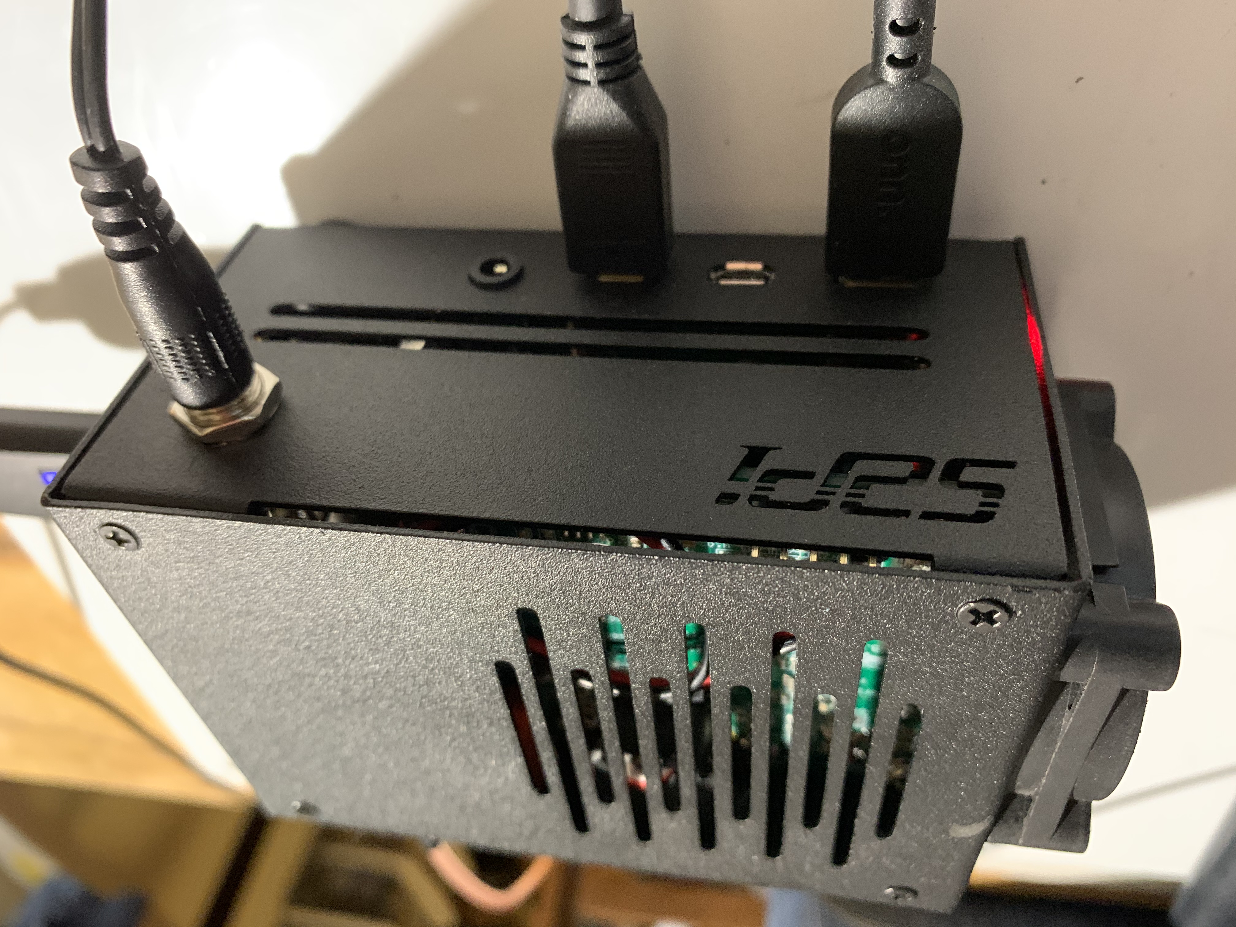
From Steli AE6OR i got the following link for a case:
Also sharing a picture from his setup:
i have not make a final setup.
Hope this helps.
73 Johan
PA3GSB
Op vrijdag 2 april 2021 om 19:06:40 UTC+2 schreef derek.d...@gmail.com:

Tech Minds
Jul 25, 2021, 11:30:57 AM7/25/21
to Radioberry
Hi there, do you have any populated pre amp boards for sale please?
Thanks,
Matt
M0DQW
YT Tech Minds

softerh...@gmail.com
Jul 26, 2021, 1:44:57 AM7/26/21
to Radioberry
Hi,
How does AE6OR plan to dissipate heat from the preamp? On the HL2 we dissipate heat from the LDMOS devices to the enclosure via the rails and a heat shim.
73,
Steve
kf7o

Gwen Patton
Jul 27, 2021, 4:17:20 PM7/27/21
to Radioberry
I'm interested in the preamp board as well. I saw Matt's YouTube video and became very intrigued!
73,
Gwen Patton, NG3P

Steli
Jul 27, 2021, 7:48:39 PM7/27/21
to softerh...@gmail.com, Radioberry
Hi I have already forgot about the preamp.
After I blew off few of the ICs that regulates the voltage for the PA transistors.( I removed that as It makes no sense in having it)
-Anybody else had this problem?
I will post some pictures of my complete transceiver with the PA and RB 4.
73's
AE6OR
--
You received this message because you are subscribed to the Google Groups "Radioberry" group.
To unsubscribe from this group and stop receiving emails from it, send an email to radioberry+unsubscribe@googlegroups.com.
To view this discussion on the web visit https://groups.google.com/d/msgid/radioberry/2ff3db3a-a518-40aa-9621-56a0992e6e56n%40googlegroups.com.
Steli
Jul 27, 2021, 8:00:21 PM7/27/21
to Tech Minds, Radioberry
I made a little L piece of aluminum the width of the two transistors and and with two screws mounted on the side of the case as you can see the screws in the pict....
On Tuesday, July 27, 2021, Tech Minds <mrmpm...@gmail.com> wrote:
Yes please share your photos, will be interesting to see.ThanksMatt
To view this discussion on the web visit https://groups.google.com/d/msgid/radioberry/CAECTniOzoOAQOd6GqUnopCw6f3pYNWevM0P-XXhfL_AJP%3DxsZw%40mail.gmail.com.
Reply all
Reply to author
Forward
0 new messages