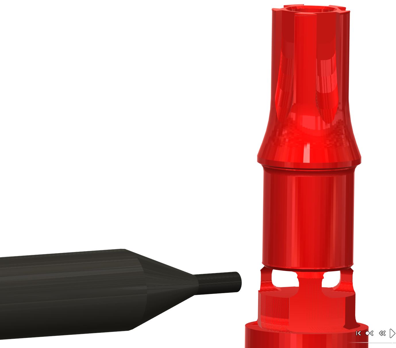
Parting off cylindrical part

vich...@gmail.com

Graham Stabler

Brad Cavallaro
Find Spiral tool path here https://pocketnc.atlassian.net/wiki/spaces/PNFUR/pages/370507881/Pocket+NC+V2+Demo+Part-Spiral

azdavi...@gmail.com
azdavi...@gmail.com
azdavi...@gmail.com
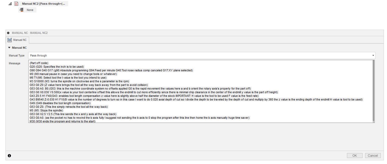
(Part off code)
G20 (G20: Specifies the inch is to be used)
G90 G94 G40 G17 (g90:Absolute programming G94:Feed per minute G40:Tool nose radius comp canceled G17:XY plane selected)
M0 (M0:manual pause in case you need to change tools or whatever)
M6 T1(M6: Select tool the t value is the tool you intend to use)
M3 S10000 (M3: turns the spindle on clockwise and the s parameter is the rpm)
G53 G0 Z0 (Z value here brings the tool all the way back away from the part to avoid collsion)
G53 G0 A0. B0.(G53: this is the machine coordinate system no offsets applied G0 is the rapid movement the values here a and b orient the rotary axis's properly for the part off)
G53 G0 X0.030 Y0.500(x value is your tool centerline offset this allows the endmill to cut more efficiently since there is minimal chip clearance in the center of the endmill y value is the part off height)
G43 Z0.5 H1 F40(G43: enables tool length compensation z value here is slightly above half the diameter of the stock IMPORTANT: H value is the tool to be used F value is the feed rate)
G43 B9540 Z-0.030 H1 F10(B value is the number of degrees to turn so in this case I want to do 0.020 axial depth of cut so I divide the depth to be traveled by the depth of cut and multiply by 360 the z value is the ending depth of the endmill H value is tool to be used)
G49 (G49 disables the tool length compensation)
G53 G0 Z0. (This line simply retracts the tool all the way back)
M5 (M5: Stops the spindle)
G53 G0 X2.5 Y2.5 (This line sends the x and y axis all the way back)
G53 G0 A0. (as the pocket nc has to rewind the b axis fully I suggest not sending the b axis to 0 stop the program after this line then home the b axis manually huge time saver)
M30 (M30 ends the program and returns to the start)