Skip to first unread message

Jacob Watt
Feb 6, 2019, 10:49:52 PM2/6/19
to Pocket NC
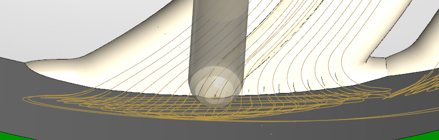
As disscussed in my other thread I was trying to mill an impeller using a climb cut with a negative lead angle (it gives a very clean cut compared to either a conventional or a 0° lead angle).
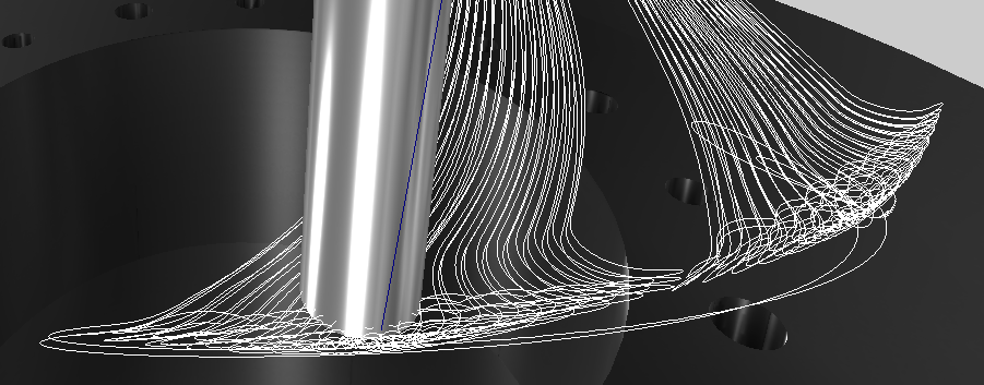
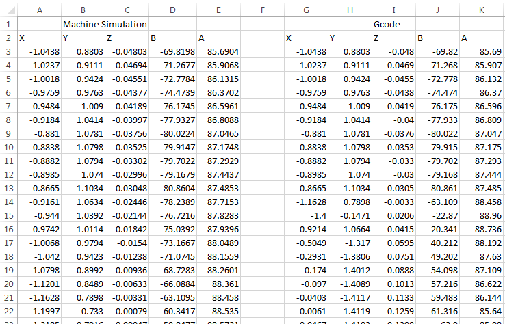
I've gotten a tool path to generate in MasterCAM that both looks good and stays within the axis limits. When I do the Machine Simulation (see first image) the toolpath looks good and doesn't loop back into the part (see 2nd image). I did a line by line comparison and for a while the X,Y,Z,B and A values in the Machine Simulation window match the generated GCode exactly, but at some points it drastically deviates (see 3rd image). Because it looks good in the MasterCAM Machine Simulator, I believe there is a glitch in the post processor.
Thanks
Jacob Watt
Feb 7, 2019, 12:28:26 AM2/7/19
to Pocket NC
Forgot to mention I have V2 ans MasterCAM 2018.

qrot...@pocketnc.com
Feb 7, 2019, 9:55:01 AM2/7/19
to Pocket NC
Hi Jacob,
This is very interesting and good to know so thank you for sharing your discoveries. I just wanted to drop a line and ask if you had heard about our new simulator? If not, check out https://sim.pocketnc.com/, it might give you a little more insight into what is going on or at least help with future projects.
Thanks!
Q Rothing
Pocket NC Customer Service
Jacob Watt
Feb 7, 2019, 2:37:44 PM2/7/19
to Pocket NC
I've been using sim.pocketnc.com a lot since I discovered the post-processor glitch. I've tried tweaking a lot of the parameters in MasterCAM and then would plug the gcode into the PNC sim to see if anything was improved. The 2nd image I included is from the PNC sim.
Reply all
Reply to author
Forward
0 new messages