Creating a custom Stenoboard.

Lenno Liu
I looked at a stenoboard and was inspired to make my own but with a few changes.

Robert Fontaine
I have been looking at the planck/quark 40% case or nice 60% case are
readily available but probably bigger than necessary and having a
custom plate made.
Hot glue and hand wiring switches. Not really sure about the keycaps
other than flat and tight so that chording isn't the pain in the bum
it is on a qwerty keyboard.
There are quite a few firmwares out there for custom keyboards that
can be used to support nkro. (geekhack discussion/github source)
I'm pretty darn sure you can build a very nice little plover custom
for under $400 all in.
> FIRMWARE/HARDWARE*
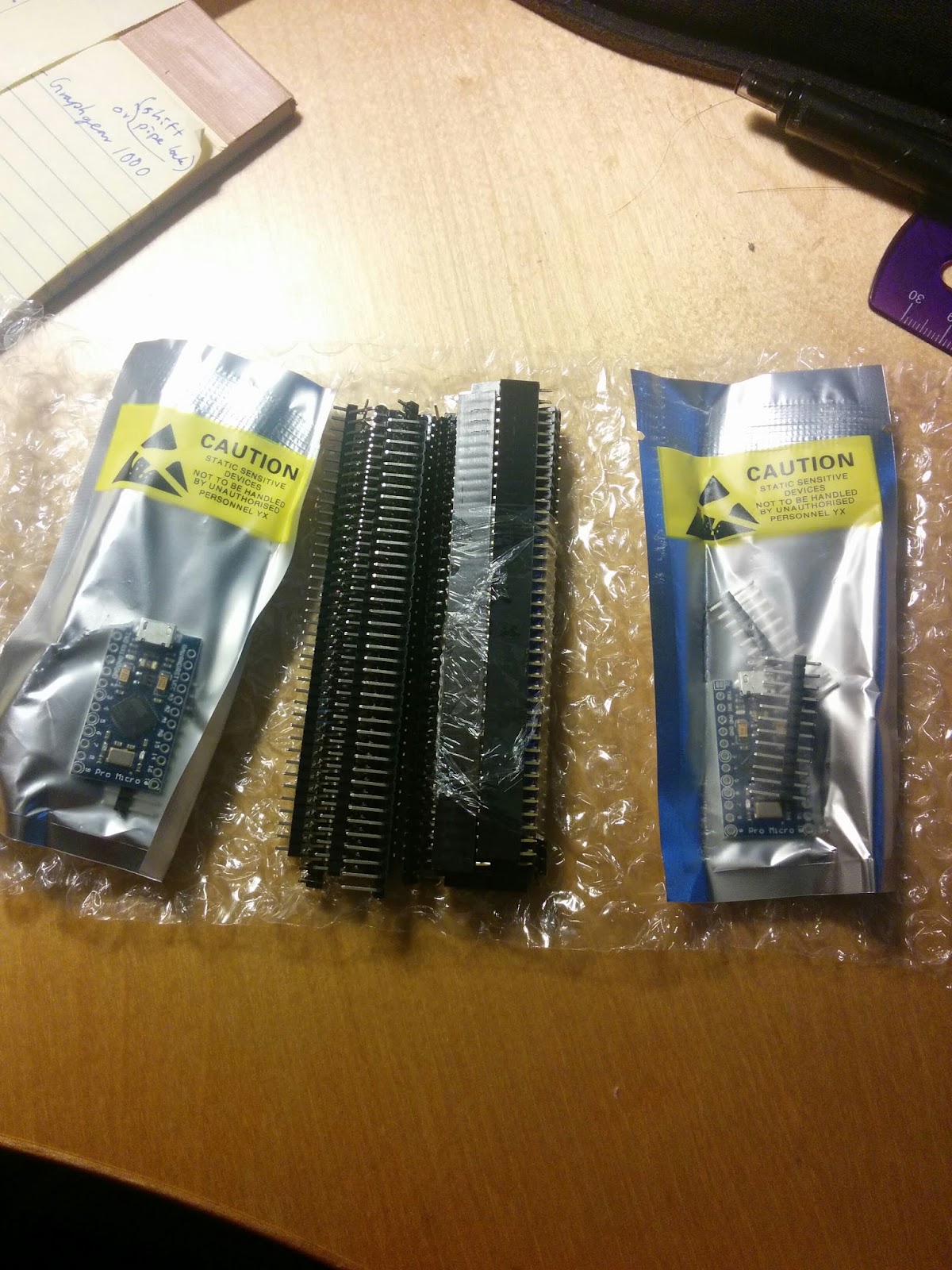
> but I decided that I will use an Arduino Pro Micro instead of an Arduino
> Leonardo.
> Why? I dislike the amount of unused stuff on the Leonardo. External power
> supply not needed, it's bigger than necessary, tons of unused pins, etc.
> Perhaps you can call me obsessed with optimization for both size and
> efficiency... I just had to.
>
> So using a Pro Micro creates a few problems.
> Instead of pins 2-13, the pro micro only has pins 2-10. After that the pins
>
> go to: 16, 14, 15, A0/18, A1...
>
> I took a quick look inside the programming and I saw that to switch around
> the pins, all I needed to do was to change the numbers. Okay! That's done.
> Now, the pins are routed 2-10 + 16, 14 and 15.
>
> However, I realized another thing. Firstly, the LED pin is pin 3, whereas
> Column 5 goes to Pin 2. This is bizarre; it separates Column 5 from the
> rest of the columns. So I switched it around.
>
> Lastly, when it's configured this way, Pin 9 is on the opposite side of the
>
> pins 10, 16, 14, 15 and A0... etc. This means that ONE Row pin has to jump
> across the board. Again, I was irked out at this and decided to move the
> pin to pin 10 and shift everything up one more.
>
> So here is the end result:
>
> LED pin: Pin 2 (originally Pin 3)
> Column Pins: Pins 4-9 (originally Pin 2, 4-8)
> Row Pins: 10, 16, 14, 15, 18/A0. (originally Pin 9-13)
>
>
> moment (and it would be my first foray into programming) so I cannot
> I also added a reset button (advised from my brother). This just resets the
>
> RAM and stuff on the Arduino and boots it up again (does NOT reset flash
> memory, so the program is still on there). In case something strange
> happens.
> It's very simple. Just connect a button between the Reset pin and Ground
> pin.
>
>
> Additional features:
>
> The Arduino interprets the columns and rows originally as this:
> {'q', 'w', 'e', 'r', 't', ' '},
> {'a', 's', 'd', 'f', 'g', ' '},
> {'c', 'v', 'n', 'm', '3', ' '},
> {'u', 'i', 'o', 'p', '[', ' '},
> {'j', 'k', 'l', ';', '\'', ' '}
>
> This is the matrix that it uses to tell what keys are being pressed down.
> You'll note that there are five empty spaces at the far right. The top two
> are used for the Fn1 and Fn2 (function 1 and function 2) keys on the
> Stenoboard.
> Those buttons are (Row 0, Column 5) and (Row 1, Column 5).
>
> mapped to the left hand board.*
> asterisk and right hand asterisk. The end result is this:
>
> {'q', 'w', 'e', 'r', 't', ' '},
> {'a', 's', 'd', 'f', 'g', ' '},
> {'c', 'v', 'n', 'm', '3', ' '},
> {'u', 'i', 'o', 'p', '[', 'y'},
> {'j', 'k', 'l', ';', '\'', 'h'}
>
> Notice that at the bottom two rows, Y and H are added (they are the qwerty
> equivalents of right hand asterisks).
>
> Why did I do this? Well right now it's a dream but I think it would be
> wonderful to type on a stenoboard like one types on a full keyboard. How?
> By mapping this: Top button only = top row. Top + Bottom = home row. Bottom
>
> only = bottom row. Of course, right now it's a fanciful thought. However, I
>
> need to implement it in the hardware before it even has a chance to be able
>
> to do it in the software, so here it is.
>
> interpreted by plover. *
> Additional changes I needed to make because of this: Gemini Protocol's
> asterisk needed to be expanded. It now looks like
>
> if (currentChord[0][4] || currentChord[1][4] || currentChord[3][5] ||
> currentChord[4][5]) {
>
> instead of
>
> if (currentChord[0][4] || currentChord[1][4]) {
>
> asterisks to work with Gemini and TX Bolt as well. *
>
> This is pretty much where I've gotten so far with about 2 days of dedicated
>
> thought-work. There are a few additions that I want to make and will be
> listed below. This list contains things that I want that I don't know how
> to implement or just haven't gotten around to doing so, and includes
> required for the circuit to work.*
> You received this message because you are subscribed to the Google Groups
> "Plover" group.
> To unsubscribe from this group and stop receiving emails from it, send an
> email to ploversteno...@googlegroups.com.
> For more options, visit https://groups.google.com/d/optout.
>
--
Thank you,
Robert Fontaine
204 293 6253
Lenno Liu

Charles Shattuck
http://ortholinearkeyboards.com/
For the Planck 40% top plate and...
https://github.com/CharleyShattuck/myforth-arduino/tree/master/doc
For info about how I made some keyboards using the Planck top plate and Cherry MX reds. The "BuildingaStenoKeyboard.pdf" document there has a bill of materials and sources for the parts I used.
I'm still experimenting with the design. I just replaced the row of number keys on top with two extra thumb keys and so far I like it.
You may not like the way I did the software since it's in Forth rather that C.
Anyway, it shouldn't hurt to see what other people are doing.
By the way, I learned about the Planck switch plates from this article...
http://syntaxblitz.net/ploverboard/
Best of luck in your project!
Charley.
Lenno Liu
Charles Shattuck
Glad to hear about your project and I hope you'll post some pictures.
Charley.
Robert Fontaine

Theodore Morin

Mirabai Knight
IX (#R-T)
VIII (#R-L)
XII (#ST-R)
etc.
StenoKnight CART Services
917 576 4989
m...@stenoknight.com
http://stenoknight.com
Ted Morin

Glen Warner
I'll get around to it ... one of these days!
Lenno Liu

Again, the biggest reason why I ask 'do you use the number bar often' is really a question of how often you type out the arabic numerals instead of the words themselves. If I end up rarely using the number bar, I might as well do a custom thing. But if it's just as important as the words themselves then i'll reconsider.
Another thing that would make me reconsider is if the number bar is used at the same time as a thumb button (apart from A and O because those are for 5 and 0, so really is # + E/U ever used at the same time as A/O? To remedy this I just need to add more number keys to the sides of the thumbs, but even that won't allow a full #AOEU).
That said, I think I'm going to use Row 4 keycaps for MOST things and use Row 3 keycaps for the thumbs, to add at least some kind of height difference. I haven't decided on the keycaps for the function keys yet; I might choose to make them lower to have a visual effect but I might end up regretting it.
Charles Shattuck
I'm no speed demon nor expert but I never got happy with the number keys across the top. I never was very good with numbers in qwerty or dvorak either. I like having the number keys on the thumb row now, so there's one data point. I'm never going to be writing at 200 wpm either.
I think you should experiment before you solder it together with the thumb keys in various places. I'm not sure I'd like the gap between the fingers and thumbs, but everyone's different and maybe you will. It's kind of fun to have the choices! I feel like it would be a long reach having the number thumb key in the middle instead of two on the sides. I reserve the right to change my mind at any time though!
Charley.
Lenno Liu
Mirabai Knight
--
You received this message because you are subscribed to the Google Groups "Plover" group.
To unsubscribe from this group and stop receiving emails from it, send an email to ploversteno...@googlegroups.com.
For more options, visit https://groups.google.com/d/optout.
Lenno Liu
Mirabai Knight
Lenno Liu

Lenno Liu
Lenno Liu
Lenno Liu


Robert Fontaine
Watching carefully. I ordered a milled blank bottom from mass drop. Eta January. Curious to see how your keycaps work out.
Lenno Liu
Robert Fontaine
They look sharp. I'm more likely to go with cherry mx. Did you consider going with a custom plate?
Lenno Liu
(Deleted last post because of a formatting error)
Robert Fontaine
Supporting a Canadian company would feel good but I know that one of the big keycap suppliers has reasonably priced flat square cherry mx keycaps for my first efforts.
I have a poker 2 for regular typing that I am quite happy with. Not sure if my steno speed will ever allow me to drop the qwerty board entirely.
The keys on half of the keycaps have 'sharp' edges where the plastic has kind-of flowed while settling, whereas on the other half they're rounded because of the same effect. Of course, a little polishing will fix that up in no time.I didn't consider custom plates because I'm a massive cheapskate and this is a budgeted semi-dedicated build.
I know I'm biased when I say that I recommend you use the Matias Quiet Linear keys, but hey. They're specifically made for stenotypes, need very little force, very quiet, etc. But again, keycaps are a huge problem so I definitely understand.
Lenno Liu
Lenno Liu
My Planck case has arrived and I've already soldered my diode array. The switches didn't fit tight enough to my liking so I decided to supplement it with epoxy along the outer edges.

I've also run into some trouble with the extension itself; the plug is thick enough to be a problem during the mounting process. But if I sand it down as much as I can, I think I should be able to cheat through it.
-Lenno Liu

Paul Beaudet
Lenno Liu
Paul Beaudet
Lenno Liu
Paul Beaudet
Multi-button issue: The original code here https://github.com/caru/StenoFW actually does its own system of recording key presses by pressing the first key, then pressing down the second key and releasing the first, then pressing the third and releasing the second, etc. This way the chord is actually electronically 'rolled' across at however fast the communication is run, and only when all keys are released.
Theodore Morin
--
Paul Beaudet
Why is giants 14 for you? SKWRAOEUPBTS → 12