Spacewar Peripheral Project (Maybe...if it works)
580 views
Skip to first unread message

slob
May 30, 2016, 11:03:47 PM5/30/16
to PiDP-8
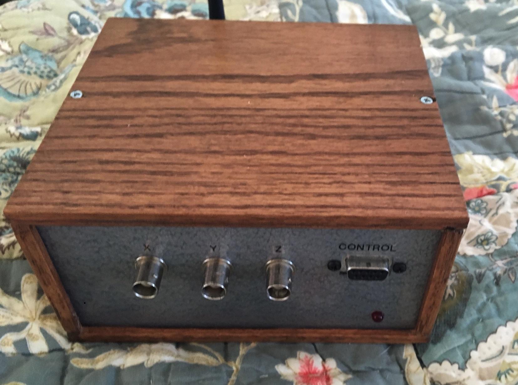
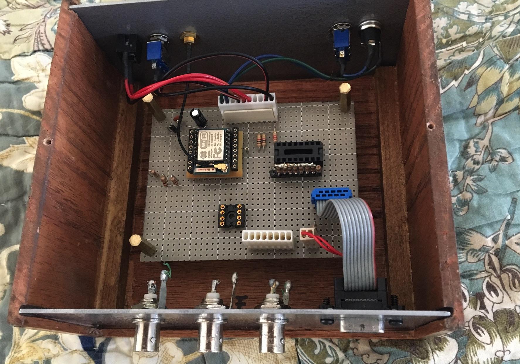
Looking at the Processing code, It occured to me, that it would be great if I could get the PiDP8 to output on a real x-y display (A Tek 604). I have a few of them and a few others that need repair. So, here is my "framework" for such a project. I'm trying to use an ESP8266 (ESP-07) wireless system on a chip to receive the bytes from the Pidp8 (with wireless output) and convert that into analog X, Y and a Z brightness signal. I had built a "scope clock" for a kit some time ago using a serial A/D converter and I built it into a Tek 620, and that worked on similar principles.
The paddles are read with a parallel/serial input chip. On paper, everything SHOULD be fast enough to do this. The challenges will be my programming skill (using the Arduino environment), careful use of the limited I/O of the ESP8266, interleaving the operation of the display with the ESP8266 wireless functions, and unknown hardware challenges. I'm waiting on the D/A chip (a TLV5617 10-bit dual), the reference, and an HC165. Another constraint is time, of which there is NEVER enough, particularly in the summer :( If anyone is thinking along these lines, well, this is a start...
The paddles are read with a parallel/serial input chip. On paper, everything SHOULD be fast enough to do this. The challenges will be my programming skill (using the Arduino environment), careful use of the limited I/O of the ESP8266, interleaving the operation of the display with the ESP8266 wireless functions, and unknown hardware challenges. I'm waiting on the D/A chip (a TLV5617 10-bit dual), the reference, and an HC165. Another constraint is time, of which there is NEVER enough, particularly in the summer :( If anyone is thinking along these lines, well, this is a start...

Obsolescence
May 31, 2016, 9:05:19 AM5/31/16
to PiDP-8
Hi,
On Tuesday, May 31, 2016 at 5:03:47 AM UTC+2, slob wrote:
Looking at the Processing code, It occured to me, that it would be great if I could get the PiDP8 to output on a real x-y display (A Tek 604).
Great! That has been on my to-do list as well, for quite some time. Maybe these ideas I had are useful to you:
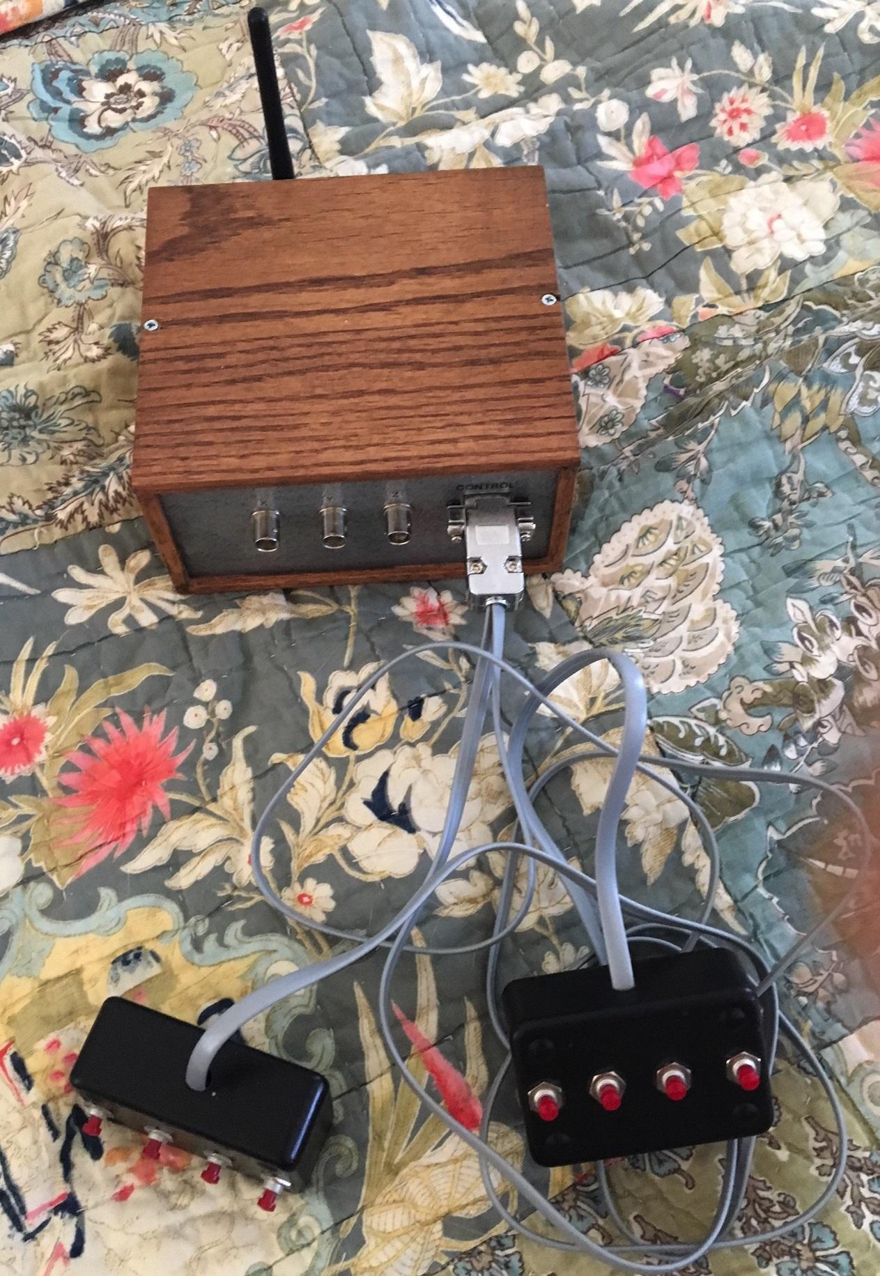
- re the paddles, and easy option is to solder wires on the back of the front panel switches, leading to a connector, straight into the paddle switches. There's a post on the forum that has the details on that. Advantage: no modification to source code needed.
- I was planning to do something with DA converters as well. Another approach could be (not necessarily better) to send the 12 bits over the front panel. As if they were 12 extra LEDs. There's spare IO pins on the schematic to add such things (i.e., an extra row of 12 bits and two-three bits that signal whether the data is for Z, Y, or brightness), via the expansion connector they could be fed into DA converters with a latch of some sort. The advantage is that it needs only a minor modification of gpio.c and - the interesting bit - some emulated instructions added in pdp8_cpu.c. You could easily make it compatible with the original XY screen hardware from DEC (and just recompile spacewar sources to drive them).
But - I never actually implement it, so easy to say :) It is a really nice project though, as it involved not only emulator code and simple modern hardware, but some hacking the inner guts of the (simh) PDP-8.
Kind regards,
Oscar.
slob
Jun 14, 2016, 1:26:38 AM6/14/16
to PiDP-8
Some progress to report: I obsessed a bit, and I finished (sort of) the hardware and got some crude software working where I can read the paddles, send them to the Pidp8, and acquire and display the display data. It appears that I can "keep up" with the speed of the Pidp8 providing the x-y points. I can recognize the starts and ships, but...
Problems that remain:
1. Setting up and optimizing an interrupt-based timer so that each "dot" lights at an identical length of time, giving adequate brightness and persistence to the display.
2. I desperately need some good bypassing on the power supply. I will be installing ceramic and tantalum caps in a day or two; I may also install a secondary 3.3V regulator that has less capacity (but tighter regulation) than the one that presently drops down the 5.0 from the USB to power the whole thing. The display is presently pretty "jumpy". In addition, I may have to allow a bit more settling time to the D/A, although it is spec'ed as very, very fast, settling in just a few microseconds.
3. Related to (2), optimizing the load/impedance of the output wiring and possibly shielding it further Wire-wrapping analog circuitry is pretty iffy as it is, although I do have good coaxial cables from the box to the display.
slob
Jun 20, 2016, 1:39:28 AM6/20/16
to pid...@googlegroups.com
So, after spending a weekend with optimization and ring buffers, I believe that I have all of the "flashiness" out of my software that can be done (with a reasonable effort). I had some crazy ideas about repeating points if the ring buffer became empty starting with the newest ones and working backwards. The phosphor on most of these general-purpose X-Y displays is by design not of high persistence. So, this may be a good as it gets on "real" hardware. I've convinced myself that the hardware/firmware can handle a significantly higher data rate. I even spent a little more for a premium D/A converter with a very fast settling time. I may explore this with other software written for it (not necessarily from a PDP8 emulation - all it knows is TCP/IP packets with a 0,0, 16-bit positive int, 16-bit positive int structure and an incoming byte representing the state of eight switches).
The ESP8266 is amazing; the way I did the firmware, it boots as a wireless access point named "VC8E-AP" with a login of PDP8; After you connect to that from any ip address (which all routes to the setup screen), you are presented with a screen to enter your credentials for your network (I'm finishing up putting in the IP address and port # of the PDP8 that defaults, of course, to 2222). Once you do that, it's stored in flash and unless you fail to connect in the future or force it to change by holding down the THRUST button on the "wedge" ship control upon boot-up in order to get to the access point screen, you won't see the setup screen again.
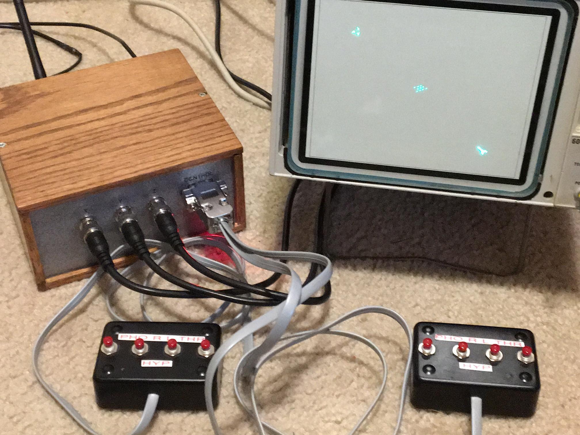
From that point, it connects to the wireless network, grabs the Spacewar data from the PiDP8 and puts it on the screen.
Holding down the PHOTON button on the wedge control upon boot-up gives you a square alignment pattern (1024/1024) to size/align your scope or x-y display to the "playing field".
Pics or it didn't happen: so, a pic is attached. I am trying to figure out how to make a video for YouTube.
I'm a fairly old guy and the thought that this was done basically with the silicon costing <15.00 and powered by a USB wall-wart is hard for me to believe. Although the 21st century has generally sucked, the ESP8266 has to be one of its high points :).
One thing that I'm not certain of with the code and VC8E; it seems to have 10 bits of resolution (=1024x1024) but the code doesn't seem to produce any odd numbered x-y points, leading me to believe that it really has only 512 distinct levels. Of course, the reality is that even my fairly good screen realistically can only "resolve", if lucky, 512 and more likely 256. in my alignment code, I skip by 4 dots on the lines and I can barely make them out individually.
The ESP8266 is amazing; the way I did the firmware, it boots as a wireless access point named "VC8E-AP" with a login of PDP8; After you connect to that from any ip address (which all routes to the setup screen), you are presented with a screen to enter your credentials for your network (I'm finishing up putting in the IP address and port # of the PDP8 that defaults, of course, to 2222). Once you do that, it's stored in flash and unless you fail to connect in the future or force it to change by holding down the THRUST button on the "wedge" ship control upon boot-up in order to get to the access point screen, you won't see the setup screen again.
From that point, it connects to the wireless network, grabs the Spacewar data from the PiDP8 and puts it on the screen.
Holding down the PHOTON button on the wedge control upon boot-up gives you a square alignment pattern (1024/1024) to size/align your scope or x-y display to the "playing field".
Pics or it didn't happen: so, a pic is attached. I am trying to figure out how to make a video for YouTube.
I'm a fairly old guy and the thought that this was done basically with the silicon costing <15.00 and powered by a USB wall-wart is hard for me to believe. Although the 21st century has generally sucked, the ESP8266 has to be one of its high points :).
One thing that I'm not certain of with the code and VC8E; it seems to have 10 bits of resolution (=1024x1024) but the code doesn't seem to produce any odd numbered x-y points, leading me to believe that it really has only 512 distinct levels. Of course, the reality is that even my fairly good screen realistically can only "resolve", if lucky, 512 and more likely 256. in my alignment code, I skip by 4 dots on the lines and I can barely make them out individually.
Oscar Vermeulen
Jun 20, 2016, 7:22:54 AM6/20/16
to slob, PiDP-8
Steve,
That is fantastic! Will you publish the schematics and code? I'd love to replicate it.
You are right, the PDP-8 spacewar code does 512x512 pixels. The source code of the program can be recompiled comfortably with the cross-compiler so it is worth looking in to.
Now I need to repair my old Tek CRT scope. My new LCD-screen scope will not deliver enough fun for this.
Kind regards,
Oscar.
On 20 June 2016 at 07:39, slob <560...@gmail.com> wrote:
So, after spending a weekend with optimization and ring buffers, I believe that I have all of the "flashiness" out of my software that can be done (with a reasonable effort). I had some crazy ideas about repeating points if the ring buffer became empty starting with the newest ones and working backwards. The phosphor on most of these general-purpose X-Y displays is by design not of high persistence. So, this may be a good as it gets on "real" hardware. I've convinced myself that the hardware/firmware can handle a significantly higher data rate. I even spent a little more for a premium D/A converter with a very fast settling time. I may explore this with other software written for it (not necessarily from a PDP8 emulation - all it knows is TCP/IP packets with a 0,0, 16-bit positive int, 16-bit positive int structure).
The ESP8266 is amazing; the way I did the firmware, it boots as a wireless access point named "VC8E-AP" with a login of PDP8; After you connect to that from any ip address (which all routes to the setup screen), you are presented with a screen to enter your credentials for your network (I'm finishing up putting in the IP address and port # of the PDP8 that defaults, of course, to 2222). Once you do that, it's stored in flash and unless you fail to connect in the future or force it to change by holding down the THRUST button on the "wedge" ship control upon boot-up in order to get to the access point screen, you won't see the setup screen again.
From that point, it connects to the wireless network, grabs the Spacewar data from the PiDP8 and puts it on the screen.
Holding down the PHOTON button on the wedge control upon boot-up gives you a square alignment pattern (1024/1024) to size/align your scope or x-y display to the "playing field".
Pics or it didn't happen: so, a pic is attached. I am trying to figure out how to make a video for YouTube.
I'm a fairly old guy and the thought that this was done basically with the silicon costing <15.00 and powered by a USB wall-wart is hard for me to believe. Although the 21st century has generally sucked, the ESP8266 has to be one of it's high points :).
One thing that I'm not certain of with the code and VC8E; it seems to have 10 bits of resolution (=1024x1024) but the code doesn't seem to produce any odd numbered x-y points, leading me to believe that it really has only 512 distinct levels. Of course, the reality is that even my fairly good screen realistically can only "resolve", if lucky, 512 and more likely 256. in my alignment code, I skip by 4 dots on the lines and I can barely make them out individually.
--
You received this message because you are subscribed to the Google Groups "PiDP-8" group.
To unsubscribe from this group and stop receiving emails from it, send an email to pidp-8+un...@googlegroups.com.
To post to this group, send email to pid...@googlegroups.com.
To view this discussion on the web visit https://groups.google.com/d/msgid/pidp-8/c54025de-847a-4e46-8717-66d0ea2251d6%40googlegroups.com.
For more options, visit https://groups.google.com/d/optout.
slob
Jun 21, 2016, 8:29:48 AM6/21/16
to PiDP-8
Yes, I intend to do this after I document it and clean up the code. The
schematic is very simple and I'm looking for the best way to present it.
This will probably be in a week or so.
One embellishment I 'd like to try in the future is using serial/USB connectivity instead of wireless, selected on the setup web page
One embellishment I 'd like to try in the future is using serial/USB connectivity instead of wireless, selected on the setup web page
To unsubscribe from this group and stop receiving emails from it, send an email to pidp-8+unsubscribe@googlegroups.com.
slob
Jul 2, 2016, 10:40:19 PM7/2/16
to pid...@googlegroups.com
So, here attached is my attempt at documentation on this project. Be aware that the design and code is working, but the code is not not finished to my satisfaction, hence, it is version 0.5. This is my first attempt ever to publish this sort of thing. There were other firsts, like, the first time I've used a schematic CAD program to do a schematic (they usually wind up existing in my head or drawn on paper).
Note: I uploaded a schematic missing a few resistors but it that schematic been replaced (it was only there for a few minutes). The version that is valid here is 1.01.
Note: I uploaded a schematic missing a few resistors but it that schematic been replaced (it was only there for a few minutes). The version that is valid here is 1.01.

Neil Higgins
Jul 3, 2016, 6:43:09 AM7/3/16
to PiDP-8
"Although the 21st century has generally sucked, the ESP8266 has to be one of it's high points :)" Quote of the century (so far)!

J.C. Wren
Jul 3, 2016, 8:57:15 AM7/3/16
to slob, PiDP-8
Steve,
I thought I'd give a whirl at compiling the code, just for the heck of it. I've used the Arduino environment sparingly (the UI is just so horrible...). I'm using 1.6.9, installed the ESP8266 board manager (2.3.0), installed WiFiManager ).12.0) and pfodParser libraries (both pfodParser.zip and pfodESP2866WiFi.zip). Selected 'Generic ESP8266 Module' for the board, and started a compile/verify. I get a ton of errors similar to this:
libraries/pfodESP8266WiFi/Parsing.cpp.o: In function `String::operator==(char const*) const':
/Users/jcw/Documents/Arduino/libraries/pfodESP8266WiFi/src/pfodESP8266WebServer.h:142: multiple definition of `ESP8266WebServer::_collectHeader(char const*, char const*)'
libraries/ESP8266WebServer/Parsing.cpp.o:/Users/jcw/Library/Arduino15/packages/esp8266/hardware/esp8266/2.3.0/libraries/ESP8266WebServer/src/Parsing.cpp:241: first defined here
For grins, I uninstalled pfodParser and pfodESP8266WiFi, and tried to build with only one or the other installed. Compiling without pfodESP8266WiFi failed immediately (as I would expect...)
Any ideas for a successful compile?
--jc
Save a life; adopt a shelter animal.
Save a life; adopt a shelter animal.
On Sat, Jul 2, 2016 at 10:40 PM, slob <560...@gmail.com> wrote:
So, here attached is my attempt at documentation on this project. Be aware that the design and code is working, but the code is not not finished to my satisfaction, hence, it is version 0.5. This is my first attempt ever to publish this sort of thing. There were other firsts, like, the first time I've used a schematic CAD program to do a schematic (they usually wind up existing in my head or drawn on paper).
On Tuesday, June 21, 2016 at 8:29:48 AM UTC-4, slob wrote:
Yes, I intend to do this after I document it and clean up the code. The schematic is very simple and I'm looking for the best way to present it. This will probably be in a week or so.
One embellishment I 'd like to try in the future is using serial/USB connectivity instead of wireless, selected on the setup web page
On Monday, June 20, 2016 at 7:22:54 AM UTC-4, Obsolescence wrote:
Steve,That is fantastic! Will you publish the schematics and code? I'd love to replicate it.You are right, the PDP-8 spacewar code does 512x512 pixels. The source code of the program can be recompiled comfortably with the cross-compiler so it is worth looking in to.Now I need to repair my old Tek CRT scope. My new LCD-screen scope will not deliver enough fun for this.Kind regards,Oscar.
On 20 June 2016 at 07:39, slob <560...@gmail.com> wrote:
So, after spending a weekend with optimization and ring buffers, I believe that I have all of the "flashiness" out of my software that can be done (with a reasonable effort). I had some crazy ideas about repeating points if the ring buffer became empty starting with the newest ones and working backwards. The phosphor on most of these general-purpose X-Y displays is by design not of high persistence. So, this may be a good as it gets on "real" hardware. I've convinced myself that the hardware/firmware can handle a significantly higher data rate. I even spent a little more for a premium D/A converter with a very fast settling time. I may explore this with other software written for it (not necessarily from a PDP8 emulation - all it knows is TCP/IP packets with a 0,0, 16-bit positive int, 16-bit positive int structure).
The ESP8266 is amazing; the way I did the firmware, it boots as a wireless access point named "VC8E-AP" with a login of PDP8; After you connect to that from any ip address (which all routes to the setup screen), you are presented with a screen to enter your credentials for your network (I'm finishing up putting in the IP address and port # of the PDP8 that defaults, of course, to 2222). Once you do that, it's stored in flash and unless you fail to connect in the future or force it to change by holding down the THRUST button on the "wedge" ship control upon boot-up in order to get to the access point screen, you won't see the setup screen again.
From that point, it connects to the wireless network, grabs the Spacewar data from the PiDP8 and puts it on the screen.
Holding down the PHOTON button on the wedge control upon boot-up gives you a square alignment pattern (1024/1024) to size/align your scope or x-y display to the "playing field".
Pics or it didn't happen: so, a pic is attached. I am trying to figure out how to make a video for YouTube.
I'm a fairly old guy and the thought that this was done basically with the silicon costing <15.00 and powered by a USB wall-wart is hard for me to believe. Although the 21st century has generally sucked, the ESP8266 has to be one of it's high points :).
One thing that I'm not certain of with the code and VC8E; it seems to have 10 bits of resolution (=1024x1024) but the code doesn't seem to produce any odd numbered x-y points, leading me to believe that it really has only 512 distinct levels. Of course, the reality is that even my fairly good screen realistically can only "resolve", if lucky, 512 and more likely 256. in my alignment code, I skip by 4 dots on the lines and I can barely make them out individually.
--
You received this message because you are subscribed to the Google Groups "PiDP-8" group.
To unsubscribe from this group and stop receiving emails from it, send an email to pidp-8+un...@googlegroups.com.
To post to this group, send email to pid...@googlegroups.com.
To view this discussion on the web visit https://groups.google.com/d/msgid/pidp-8/c54025de-847a-4e46-8717-66d0ea2251d6%40googlegroups.com.
For more options, visit https://groups.google.com/d/optout.
--
You received this message because you are subscribed to the Google Groups "PiDP-8" group.
To unsubscribe from this group and stop receiving emails from it, send an email to pidp-8+un...@googlegroups.com.
To post to this group, send email to pid...@googlegroups.com.
To view this discussion on the web visit https://groups.google.com/d/msgid/pidp-8/91cdd375-893d-4907-8035-d6169d397031%40googlegroups.com.
slob
Jul 3, 2016, 11:54:31 AM7/3/16
to PiDP-8, 560...@gmail.com, jcw...@jcwren.com
Hmmm... the _only _library I downloaded was the "pfodESP8266BufferedClient" library. Using the others may result in conflicts with other libraries like the webserver, and so on. I would remove the other pfod libraries and load only that. I should make this more clear.
Well, the price is right on the Arduino IDE... :) but people have set up other IDE's for it (I think Eclipse and Visual Studio have been done); I just haven't explored those.
Another thing that can be done with the ESP8266 (with no other active components at all) is a "transparent bridge", where you can put all of your RS-232 peripherals on WiFi, which should be of interest to us, who are still making DB-25 cables in 2016.
To unsubscribe from this group and stop receiving emails from it, send an email to pidp-8+unsubscribe@googlegroups.com.
To post to this group, send email to pid...@googlegroups.com.
To view this discussion on the web visit https://groups.google.com/d/msgid/pidp-8/c54025de-847a-4e46-8717-66d0ea2251d6%40googlegroups.com.
For more options, visit https://groups.google.com/d/optout.
--
You received this message because you are subscribed to the Google Groups "PiDP-8" group.
To unsubscribe from this group and stop receiving emails from it, send an email to pidp-8+unsubscribe@googlegroups.com.
J.C. Wren
Jul 3, 2016, 12:17:31 PM7/3/16
to slob, PiDP-8
Ah. I missed that pfodESP8266BufferedClient was yet a third download from the guy's page. He should really put that up on github or somewhere, instead. I'll remove those other two and load that one when I get back home.
Although sometimes frowned upon, in addition to a link to his page, you might consider adding a "Install these libraries" and provide some direct links, as a group. Took me a couple of seconds to see that in addition to the arduino.cc link you had, there was also the ESP8266 board library link right below it.
--jc
Save a life; adopt a shelter animal.
Save a life; adopt a shelter animal.
To unsubscribe from this group and stop receiving emails from it, send an email to pidp-8+un...@googlegroups.com.
To post to this group, send email to pid...@googlegroups.com.
To view this discussion on the web visit https://groups.google.com/d/msgid/pidp-8/c54025de-847a-4e46-8717-66d0ea2251d6%40googlegroups.com.
For more options, visit https://groups.google.com/d/optout.
--
You received this message because you are subscribed to the Google Groups "PiDP-8" group.
To unsubscribe from this group and stop receiving emails from it, send an email to pidp-8+un...@googlegroups.com.
To post to this group, send email to pid...@googlegroups.com.
To view this discussion on the web visit https://groups.google.com/d/msgid/pidp-8/91cdd375-893d-4907-8035-d6169d397031%40googlegroups.com.
For more options, visit https://groups.google.com/d/optout.
--
You received this message because you are subscribed to the Google Groups "PiDP-8" group.
To unsubscribe from this group and stop receiving emails from it, send an email to pidp-8+un...@googlegroups.com.
To post to this group, send email to pid...@googlegroups.com.
To view this discussion on the web visit https://groups.google.com/d/msgid/pidp-8/d4e4dd74-73b5-4350-aa10-b55f16aa31cd%40googlegroups.com.

AB
Oct 1, 2017, 10:35:53 PM10/1/17
to pid...@googlegroups.com
Gents, just wanted to resurrect this thread. I finally have a little spare time (while I wait for Oscar's PDP-11 - no pressure Oscar :-)!!!) and wonder if there's been any recent development in Spacewar as a PidP Project? I really want to pursue using a real screen (i.e. Tektronix 604 variety) and build the home-made controllers... but am low/moderate in my soldering skills but low/verylow in my general electronics/diagnostics skills... thanks in advance for any guidance.
cheers
Andy
slob
Oct 5, 2017, 2:09:28 PM10/5/17
to PiDP-8
I haven't really done anything with it since I finished* it...again, the code works, but is too flashy to use in "stars background" mode. I believe that this could be solved with better code. Or with an ESP-32, with more ram,much faster, and with potentially better multitasking (I MAY do this).
I don't intend to make boards, etc. for it, but the schematic and instructions are there...
I've been wondering if this is considered "illegitimate" because it isn't like the original hardware in design or in execution. In my defense, the entire system starting with SiMH isn't "legitimate" by purist standards, either :) And, being wireless from the PiDP8 to the unit and scope, it is convenient (sort of). But not many people have analog scopes (never mind superior analog X-Y displays) around anymore, either, so if anyone pursues this, it isn't like hundreds would be made.
Spacewar works and looks much better in the Processing version (that version I modified for a higher-resolution screen).
*as finished as anything gets around here.
Obsolescence
Oct 6, 2017, 4:56:43 AM10/6/17
to PiDP-8
On Thursday, October 5, 2017 at 8:09:28 PM UTC+2, slob wrote:
I've been wondering if this is considered "illegitimate" because it isn't like the original hardware in design or in execution.
More illegitimate than a Raspberry Pi? :)
At some point, it would be cool to code up the dedicated VC-08 instructions in PDP8_cpu.c so it can be used by the original programs.
Regards,
Oscar.

higgins...@gmail.com
Oct 6, 2017, 8:02:32 AM10/6/17
to PiDP-8
I just found this really cool HAT for the Raspberry Pi. It's just what I have been looking for for another project, but I thought it might be worth sharing in this context:
https://www.waveshare.com/high-precision-ad-da-board.htm
It uses the TI ADS1256. I have a design for a similar board using the ADS1258 (4 times faster) but that board does not have a DAC.
Incidentally these ADCs are a 4th order delta-sigma type - 24-bit resolution and they go like stink. Amazing what you can get for $10 these days :-)
higgins...@gmail.com
Oct 19, 2017, 11:20:53 PM10/19/17
to PiDP-8
Off-topic follow-up to my off-topic response: I purchased two of these HATs and built the sample software; and they appear to work very nicely.
Reply all
Reply to author
Forward
0 new messages