Show us your kits - completed PiDP-11s

Neil Higgins

terry-...@glaver.org
In eager anticipation of completed PiDP-11s becoming operational, I am creating this thread for “brag” shots and construction stories - analogous to the thread in the PiDP-8 group. -NO- “mine’s biggier than yours” claims, please - we know they are all the same size. But if you do anything innovative or cute, show us!
Neil Higgins

Christopher Purdy
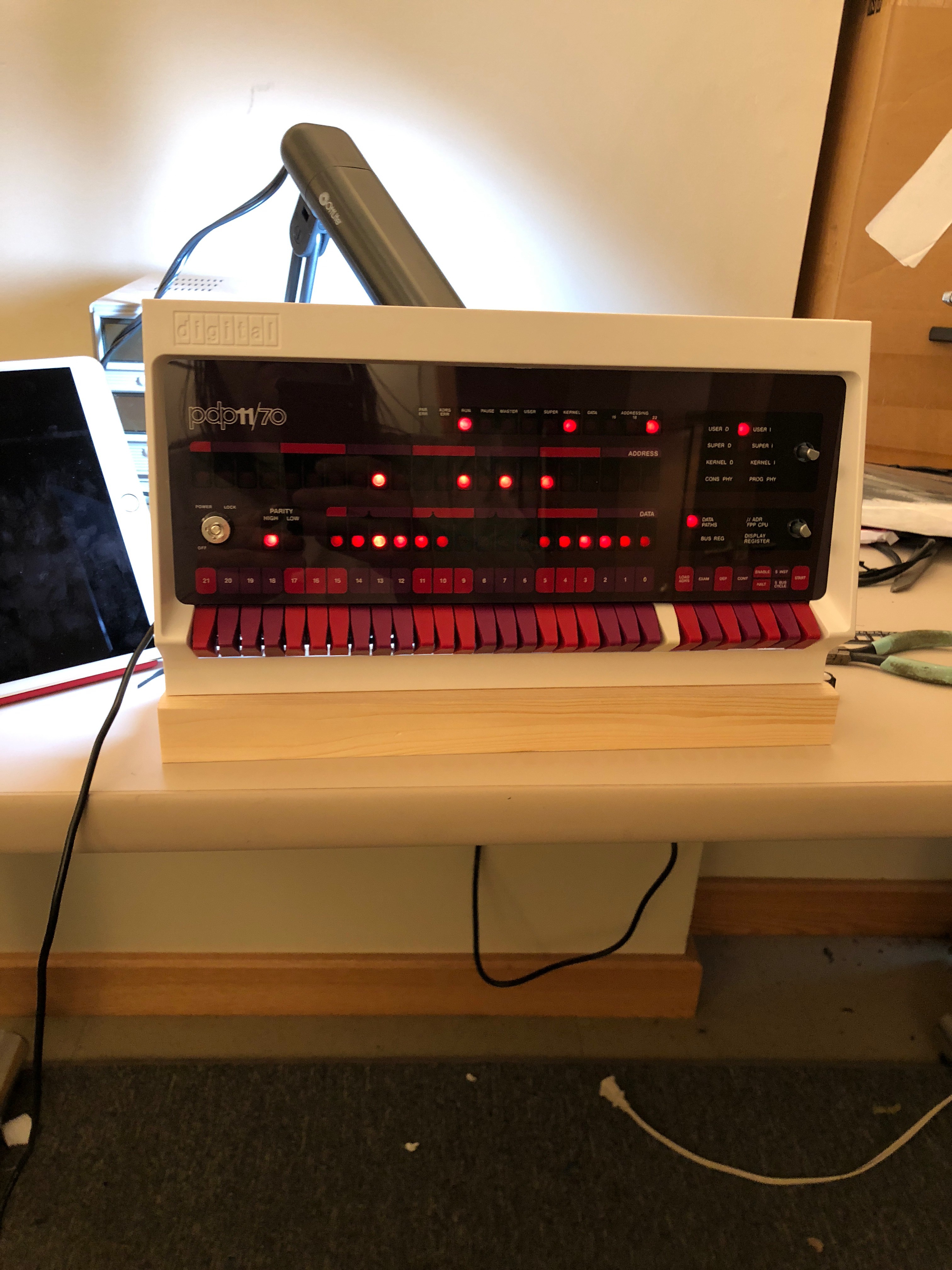
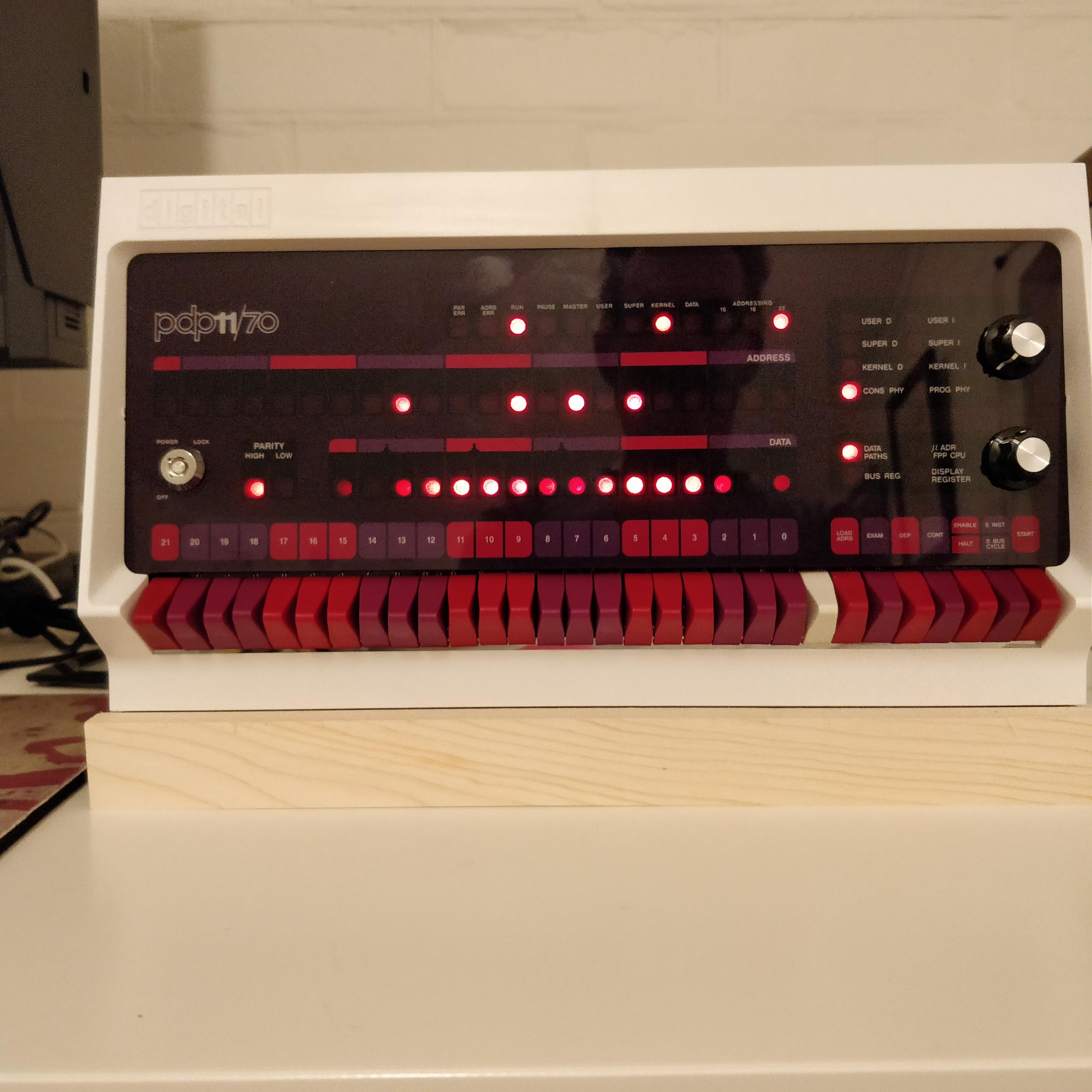
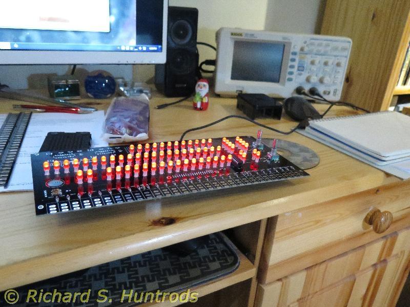
I have NO patience and put the kit together last night, a bit faster than I should have... my first free evening.
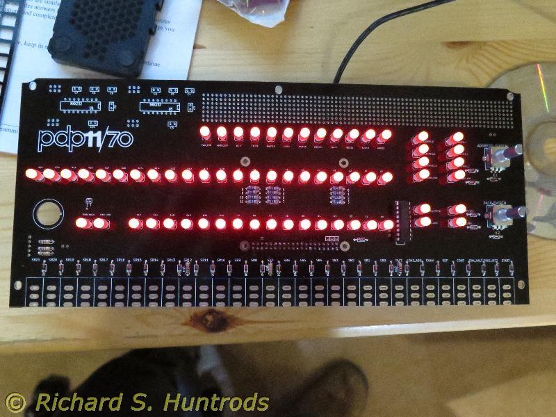
Yes - my switches aren’t the straightest... but, oh well... I was worried about over heating them.. and they didn’t like to take solder - lots of cold joints. I had to hit the ends with sandpaper and re-solder several.
All in all, Oscar’s kit is excellent.. and if you observe good soldering practices- you should have no issues.
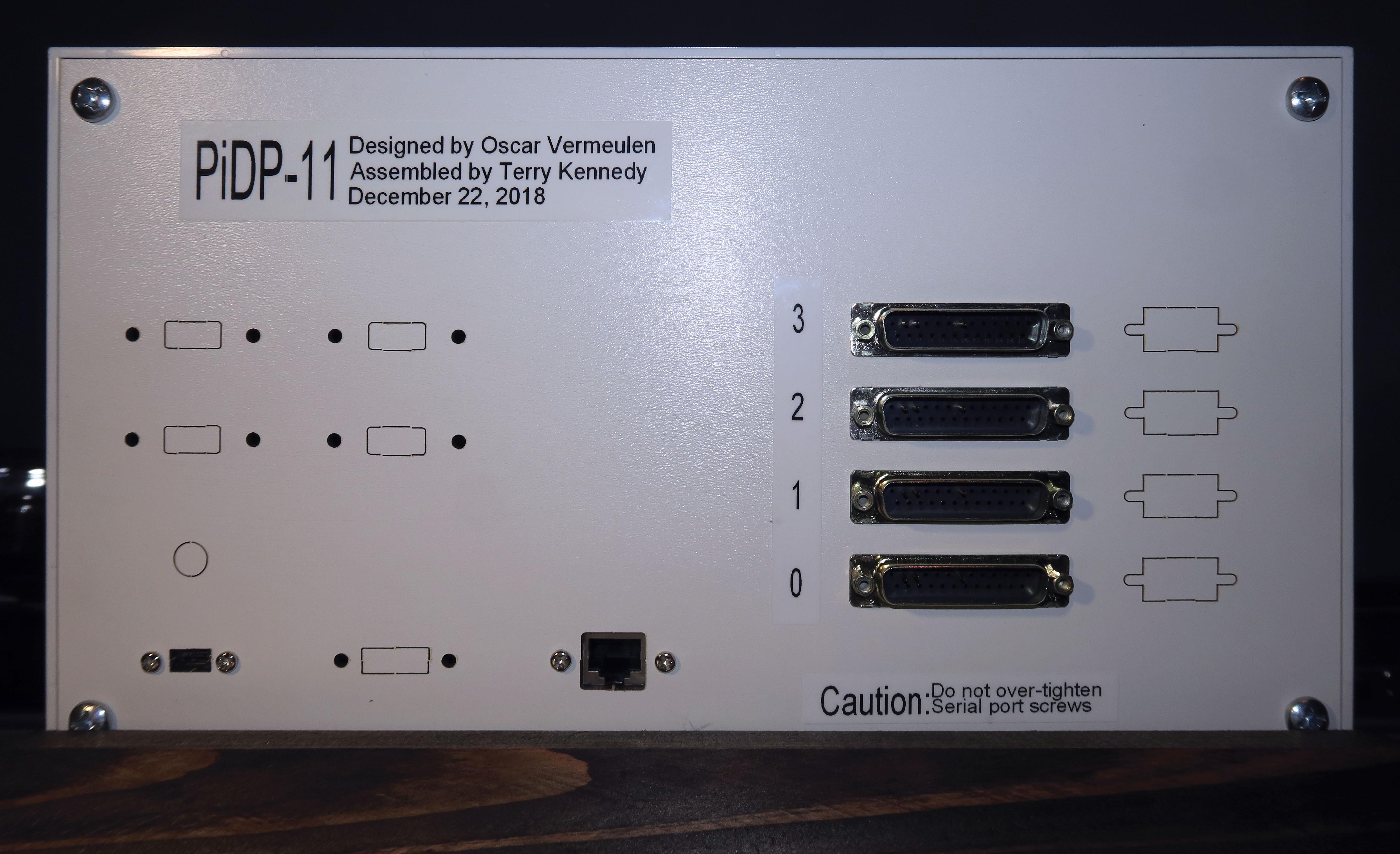
Still need to work out the back panel and mount, but everything is working!

Chris Wiener


oscarv
On Thursday, July 5, 2018 at 12:58:06 AM UTC+2, Chris Wiener wrote:
1. Oxidation on switches should be removed before soldering. Not all switches had this problem but I wish I had cleaned each one before assembly (no problems so far).
2. Should the LED cover be left on the final product? Pictures and instructions are unclear.
3. When attaching finished PCB to case, tightening some of the screws causes the PCB to flex. Likely that standoffs are not long enough. Suggestions for fix would be helpful.
5. Switch fixer should be used before soldering first switches.

Nigel Johnson
On Monday, July 2, 2018 at 7:25:27 PM UTC-4, Neil Higgins wrote:
oscarv
On Monday, July 9, 2018 at 1:58:00 AM UTC+2, Nigel Johnson wrote:
I had a problem with the back panel. Just pushing with my thumbs to break out one of the holes in the back, the board itself split at the ppoint of the edge of the hole I was trying to break out right to the edge. I recommend putting the back panel on a flat surface, on top of a magazine to allow some play, and tapping gently with a drift punch to get them out.
Nigel Johnson
On Monday, July 2, 2018 at 7:25:27 PM UTC-4, Neil Higgins wrote:

Jodie Hobson

My only comment regarding assembling the kit is to make sure the switch bodies and and LEDs/spacers are tight against the printed circuit board before soldering.


For the HDMI connector I utilized a 'version B' right angle adapter from https://www.bluejeanscable.com.


Mark Matlock
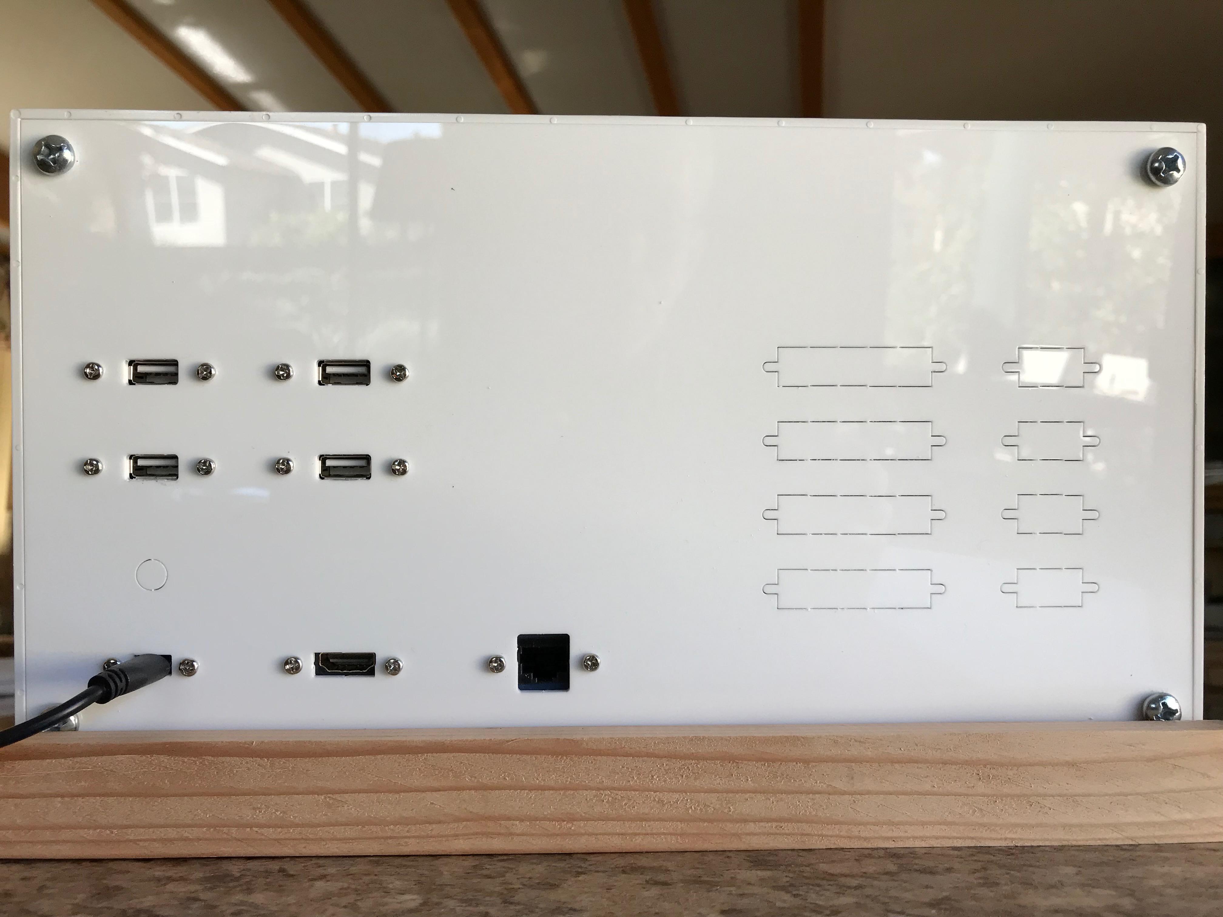
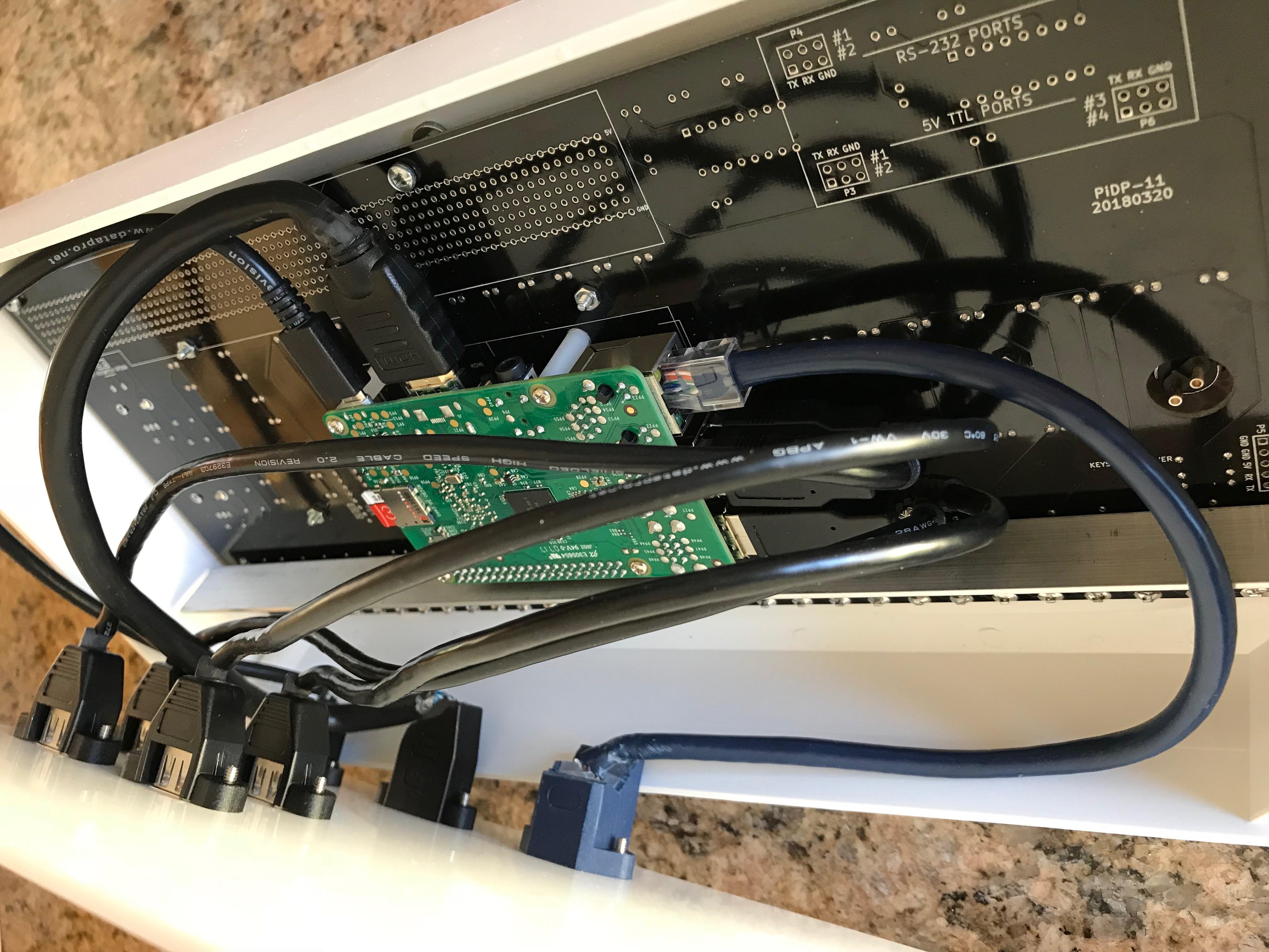
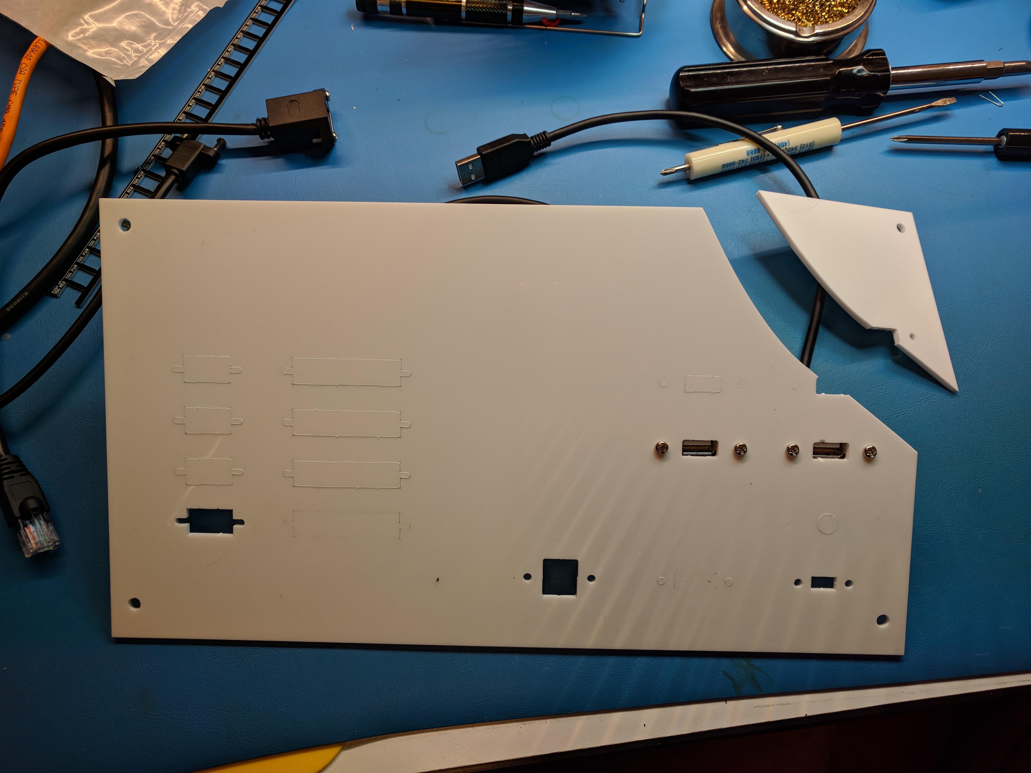
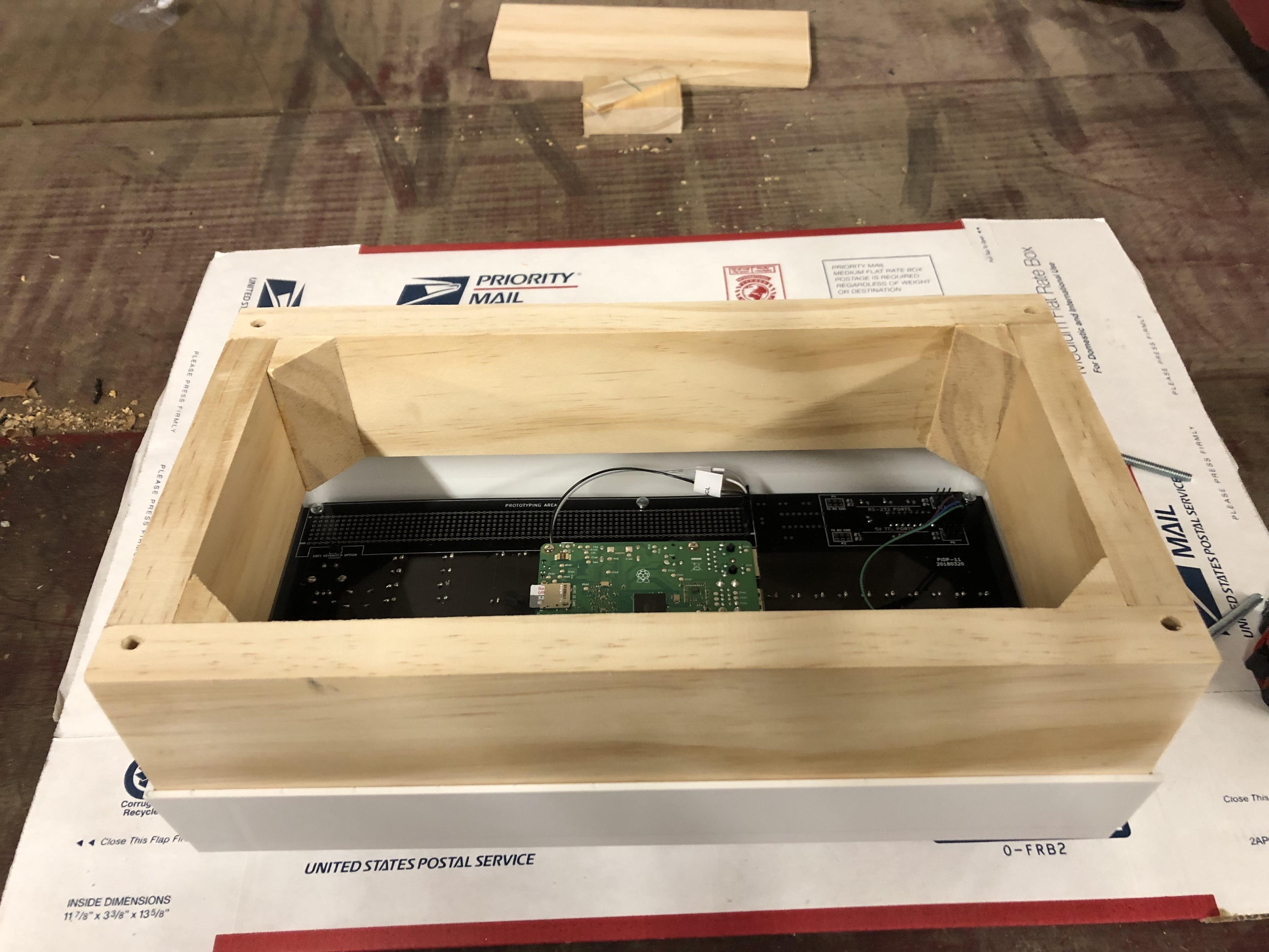
I got the clear modified laser-cut panel back from the fab shop (Polou $23 for the cut and $7 for the acrylic) . This used the laser pattern that Oscar sent me, but I moved several things closer to the center removed two of the RS232 cut outs to reduce the holes add a cutout for a small voltmeter (not yet connected). Also, I don't yet have the HDMI cable I need (misplaced it and guess the only way to find it is order another). The wooden frame is described in an earlier post but that gives good clearance for the cables and also weights the case so switch actions are easier. I also added a cut out for a small voltmeter to monitor +5V power in the box. I used the .pdf and modified it with LibreOffice and that work ok for Polou which gave me a quote in a day and cut it and shipped it the next day even though I didn't ask for rush.
I learned several things that would made the next panel better. First, I made it from 6mm thick acrylic which is quite strong, but places where some plastic was left to hold the cut out in place was too much for this thickness. I would make all the cuts complete. I had to pound out some all of the cut outs and some caused fractures you can see in the photo. Next the thickness requires that whole power connectors, USB connector etc fit through the holes some I had to dremel them larger which on the next one I'd just cut larger.
So I still need to hook up the HDMI cable connector, some RS232 ports, the voltmeter and the internal I2C temperature hack. But I really do like to be able to show someone what's inside without disturbing cables connected to the Pi.
Mark
all the holes need to be lareg enough

Louis Mamakos

Neil Higgins
(Voyeriastic, perhaps, but I like cruising the photos to see what else my “bretheren” have in their man caves)
Nice job, by the way.
Neil Higgins
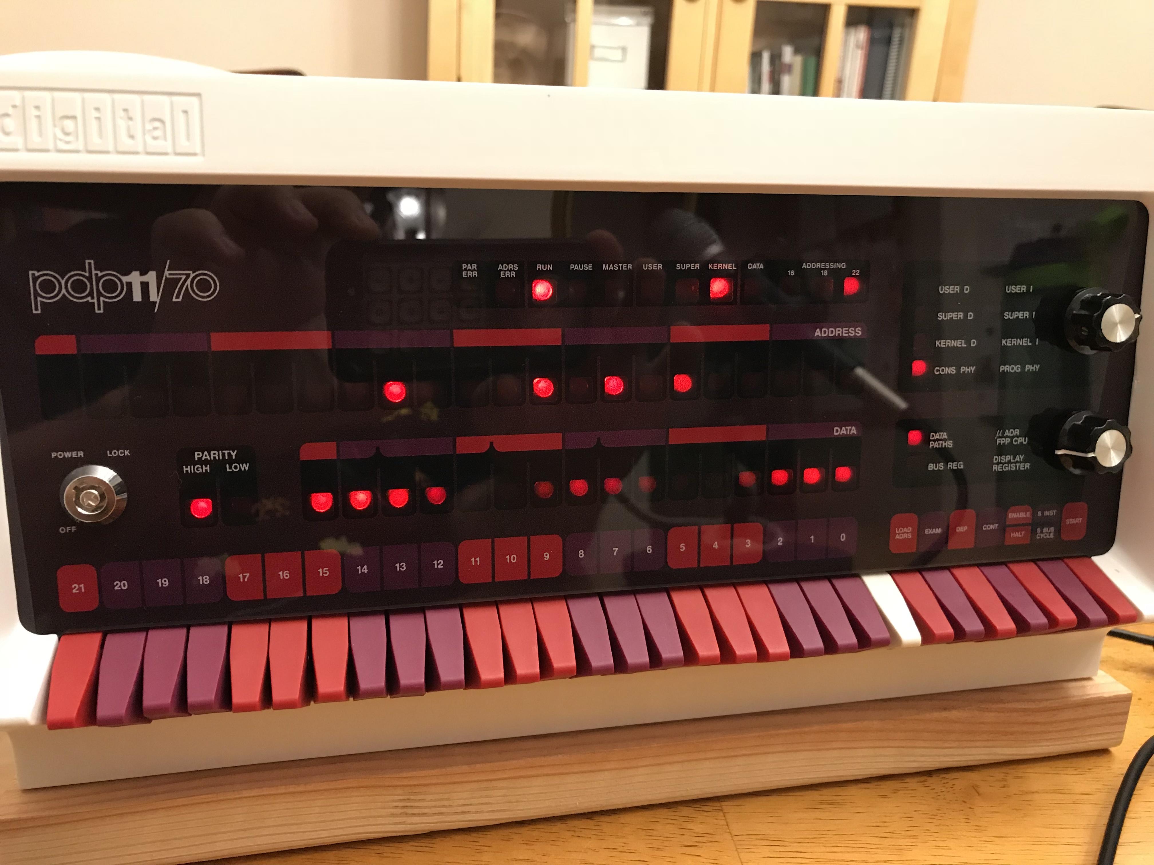
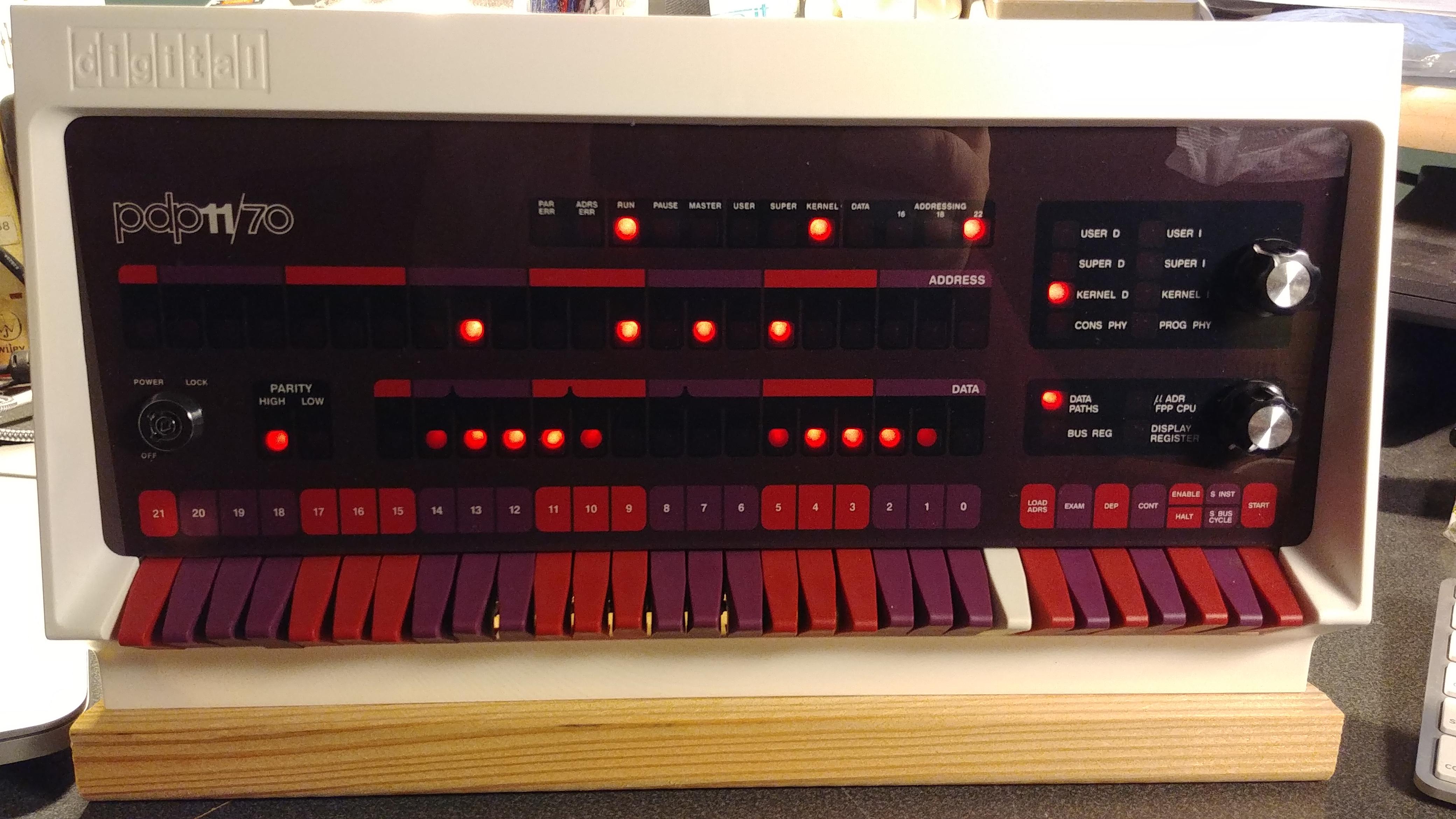
Here's mine.
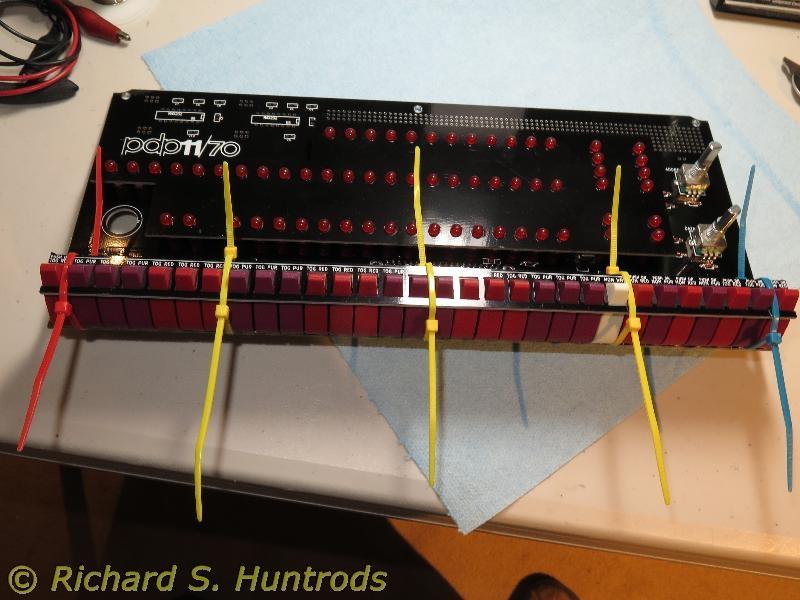
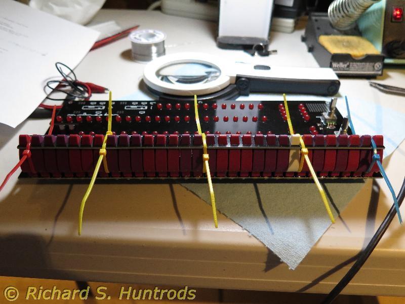
Using rubber bands around the switch "fixer" (outer assembly jig) to hold the switch assembly to the PCB is a great idea. Sadly, I do not have "the knack" mechanically, so despite my best efforts, one of the switches ended up noticeably out of alignment. Oh well.
I like to remove the solder flux from finished PCBs. This is a long, thankless task involving lots of Isopropyl Alcohol (not the pharmacy variety, which has water in it; the paint store variety, which is pure) and a soft toothbrush. It works well enough, but probably isn't too good for the future temperature of the planet.
To separate the Pi from the PCB, I used a rectangle of Mylar sheet, held in place with a strip of double-sided tape.
I also made a little Mylar washer to go between the key switch nut and the front panel.
I added a metal washer between the screw/nut combo which attaches the PCB to the standoffs. This bulked it out just enough to prevent the PCB from warping noticeable when the screws are tightened.
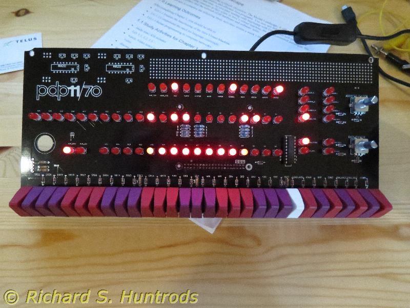
On my kit, the LEDs came out just a little above-centre in their windows.
I haven't done anything about the rear panel yet. Judging by the difficulties some have experienced with the power supply cable, I think I will try to get a stand-alone, panel-mounted USB socket (about $12 in Australia) and hand solder the wires from a stripped-off USB cable.
I will probably attach the case to the base board (for stability) after painting the board a nice, metallic grey colour.
All in all, a superb kit, Oscar. Thank you so much for your gargantuan effort in giving us this lovely piece of memorabilia.

José María
> post office was kind, and the shipping box arrived here with no damage
> showing.
>
> My kit went together just fine.. right up until I started punching out
> holes in the rear panel. I think the push-out panels are a bit too
> reinforced since I managed to fracture off one of the corners while
> trying to punch out one of the holes. So sad, but I'll get over it.
> I'll see if I can glue it up, or perhaps arrange to purchase a
> replacement and be quite a bit more careful..
>
> I sort of like the idea of a clear back panel as someone had
> mentioned; maybe I'll try something like that.
>
> Even with the cut outs as they are, getting the Adafruit extension
> cables in there is pretty difficult since there's not much depth
> available for the connector bodies. Just another 3 or 4cm would help
> quite a bit. Also, the pattern for the panel mount micro-USB female
> to micro-USB male extension cable doesn't quite fit the hole I was
> trying to; I end up jamming it in the larger DB-9 size hole instead.
>
> Thanks for the wonderful kit! My co-workers are
> amazed/jealous/perplexed when they see it.
>
> louie
(Sodium Bicarbonate) making a cord in inner side (just Google for
Cyanoacrylate baking soda). It makes a very strong union!

andy
José María
El 08/08/18 a las 18:09, andy escribió:
Robin Lauryssen-Mitchell
Neil Higgins

Frank Wortner

andy
On Monday, July 2, 2018 at 7:25:27 PM UTC-4, Neil Higgins wrote:
Mark Matlock
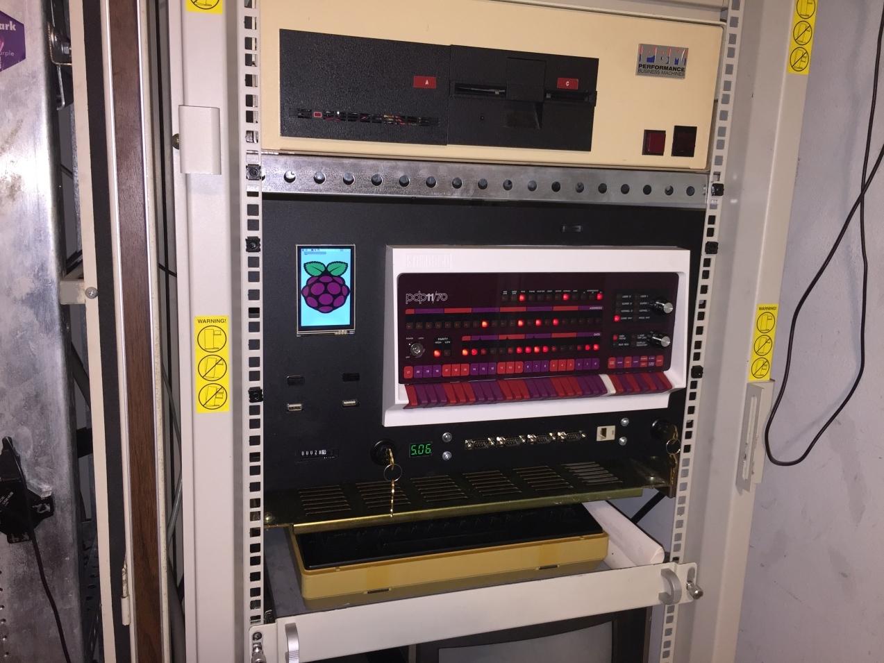
I love your rack mount ideas! Very nice work. The volt meter and hour meter are nice touches as well. Now you just need one of Henk;s
RK05 replicas to go with it.
Best,
Mark

Drew Rogge
On 8/25/18 4:03 PM, andy wrote:
> Still a work in progress, I had some blank aluminium blanking plates lying around so I went to town cutting out a home for my PiDP11 box and connectors. As I realised that I had spare space I added a few extra fun items - a voltmeter and an hour meter. I originally wanted an analog voltmeter but I couldn't quite squeeze it in :-)
> Andy
>
> On Monday, July 2, 2018 at 7:25:27 PM UTC-4, Neil Higgins wrote:
>
> In eager anticipation of completed PiDP-11s becoming operational, I am creating this thread for “brag” shots and construction stories - analogous to the thread in the PiDP-8 group. -NO- “mine’s biggier than yours” claims, please - we know they are all the same size. But if you do anything innovative or cute, show us!
>
> You received this message because you are subscribed to the Google Groups "[PiDP-11]" group.
> To unsubscribe from this group and stop receiving emails from it, send an email to pidp-11+u...@googlegroups.com <mailto:pidp-11+u...@googlegroups.com>.
> To view this discussion on the web visit https://groups.google.com/d/msgid/pidp-11/8c4edbf4-27ac-4a75-a091-7fdfb5ae1c07%40googlegroups.com <https://groups.google.com/d/msgid/pidp-11/8c4edbf4-27ac-4a75-a091-7fdfb5ae1c07%40googlegroups.com?utm_medium=email&utm_source=footer>.
> For more options, visit https://groups.google.com/d/optout.
--
Drew Rogge
dr...@dasrogges.com
Phone: 8934OOO629OO4829631OOOOOOO
andy
andy

Henk Gooijen
Last week I was looking at how to trim the white bezel at the rear side. My plans (just in my head) is building a small rack just like you, but then to scale. thus the width of the rack is exactly for the PiDP-11/70. Relatively easy to make from standard aluminum L-shape profile from the DIY shop.
I also plan to make a "box" onto which the PiDP-11/70 is attached. That is not how the real 11/70 was.
On the RK05 front panel ... I have the I2C interface working. I can control the 7 LEDs (PWR is directly connected to power) and read the two switches. A few more I/Os are needed such as door lock solenoid, door open/closed sensor, drive # (4 drives max, but nobody will do that ...) and 7 supported disk containers per cartridge.
I must say that the PiDP-11/70 console mounted in the rack looks like it is real stuff !
Neil Higgins
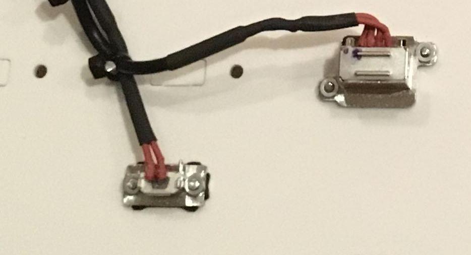
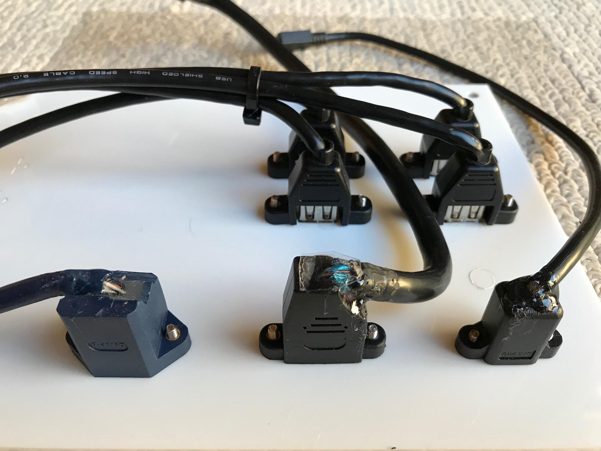
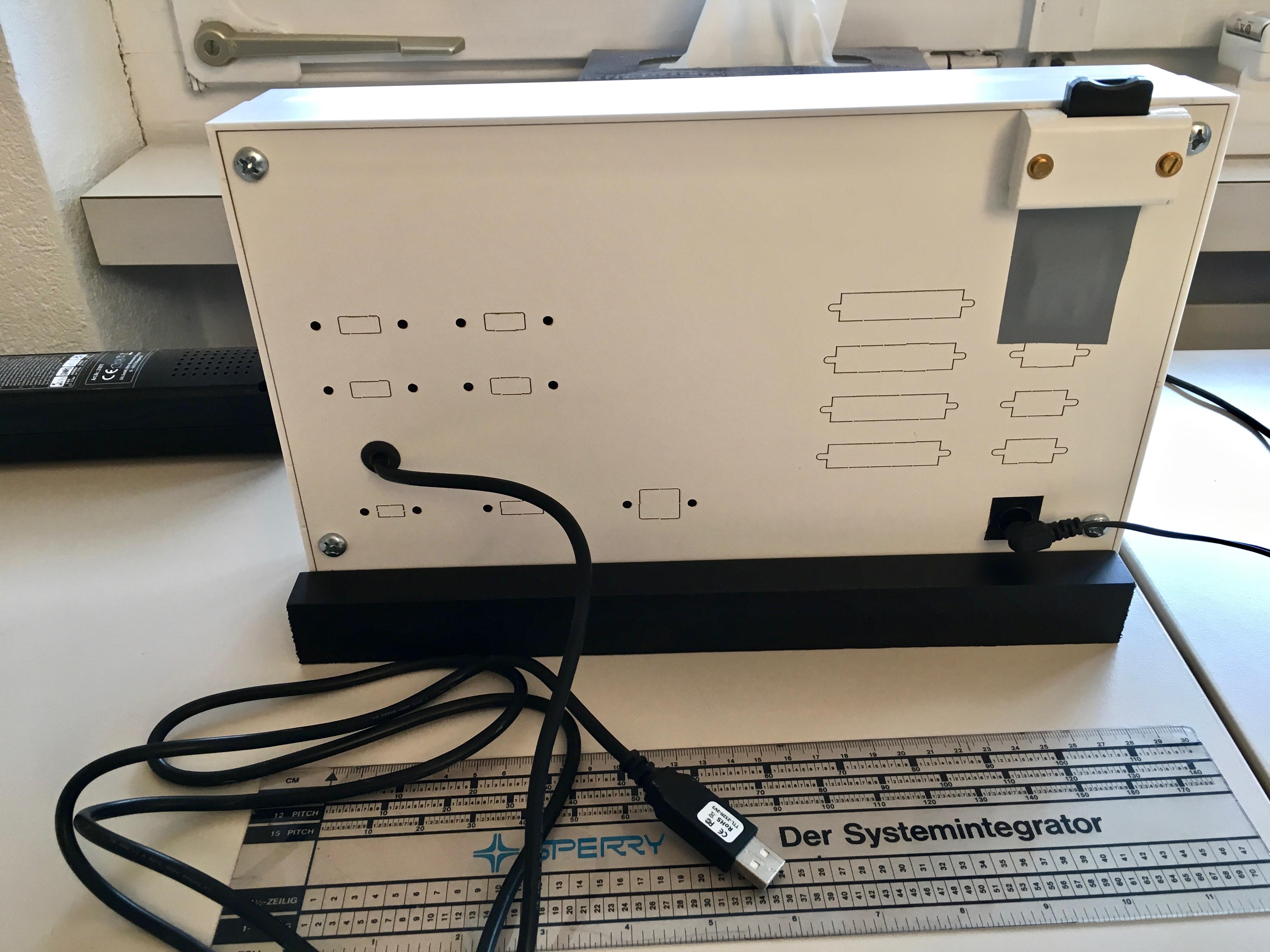
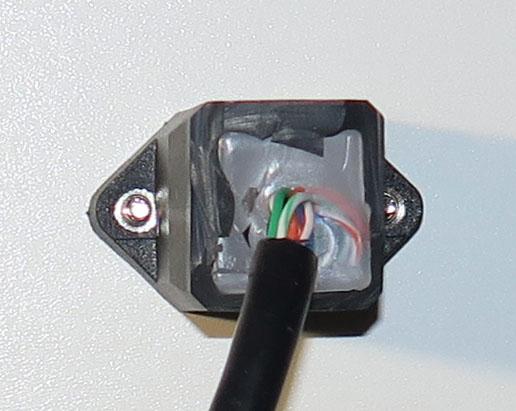
I decided to use panel-mount connectors, rather than pre-fabricated cables, for power supply and USB. See previous posting. These connectors did not fit into the pre-formed holes, so I had to make new holes by routing and filing. The connectors that I obtained are designed for PCB mounting, but with some care I was able to attach the wires from stripped-back USB cables by soldering, and strain relieve them with heatshrink tubing (don't forget to slide on the heatshrink before soldering!!). I also tied the two cables to a machine screw, set in one of the spare connector mounting holes, to minimise movement. For the power supply cable I used a recent-vintage Belkin cable (blue in the photos) and was surprised, and pleased, to find that the power supply wires were quite generously sized.
I also decided to attach the moulded case to the wooden base, removably. I achieved this by putting threaded inserts into the base. Threaded inserts of various kinds are available - I used press-in plastic ones. The wood supplied with the kit is very soft and coarse-grained - difficult to drill without making a mess, but it can be done. Firstly drill holes at the bottom of the case near the rear, then mark them through to the wooden base. Clamp the base firmly to a piece of waste timber, and the use a high-speed spade bit - the type with little spurs at the outside edges. Drill slowly until you are through the base. Note: You have to drill at right angles to the mounting surface, not to at right angles to the underside. Then press in the inserts.
Finally, I decided that wood grain would be out of character for my PiDP-11 so I filled, sealed, sanded and painted the base a nice metallic black colour. It looks great. I have attached a few photos.
Henk Gooijen
The wooden base is very nice in black. I cannot decide whether matte or high-gloss would be coolest ...
Neil Higgins
andy
Neil Higgins
I got these from Element14 for about AU$25 total, plus postage. The part numbers are:
http://au.element14.com/amphenol-icc-commercial-products/musbk55230/sealed-usb-2-0-micro-ab-rcpt-ip67/dp/2708978?CMP=i-55c5-00001621
and
http://au.element14.com/amphenol-commercial-products/musbra11130/sealed-usb-2-0-type-a-receptacle/dp/2708979?CMP=i-55c5-00001621
These are moisture-proof bulkhead connectors, so over-spec’d for the job. They have a blind thread and a rubber gasket for moisture proofing. Also, they come without screws, and none of the machine screws I had would fit the threads - so I had to do ‘surgery’ with my drill and Dremel, so that I could use ‘vanilla’ M2.5 machine screws.
With luck you might find Amphenol (or other) variants that are simpler and cheaper.
andy

Rick Reynolds


Ian Parr
Neil Higgins

Stephen Casner

Roger Arrick

Thomas Lake
Roger Arrick
Laser-cut MDF, real switches, acrylic faceplate, .125 alum top. Even has LEDs - I should hook those up to something.
rA

Neil Higgins

Brian Peacock

Johnny Billquist
> Thanks Oscar for a really wonderful kit and also thanks to all those who
> have shared their stories whilst building their PiDP-11s as all of those
> postings helped me along the way. My next steps are to install it in a
> computer rack and configure (Raspbian) to run model train automation
> software (in addition to simh), thus giving the impression that the
> model trains are under the control of a 40 year old mini-computer. If
> only I could run such software under RSX-11M ...
Johnny
--
Johnny Billquist || "I'm on a bus
|| on a psychedelic trip
email: b...@softjar.se || Reading murder books
pdp is alive! || tryin' to stay hip" - B. Idol

Nick Sargeant
andy
On Wednesday, October 17, 2018 at 4:03:46 PM UTC-4, Roger Arrick wrote:
oscarv
On Friday, October 19, 2018 at 3:16:16 AM UTC+2, Brian Peacock wrote:
to run model train automation software (in addition to simh), thus giving the impression that the model trains are under the control of a 40 year old mini-computer. If only I could run such software under RSX-11M ...
Neil Higgins
Brian Peacock

Mark G Thomas
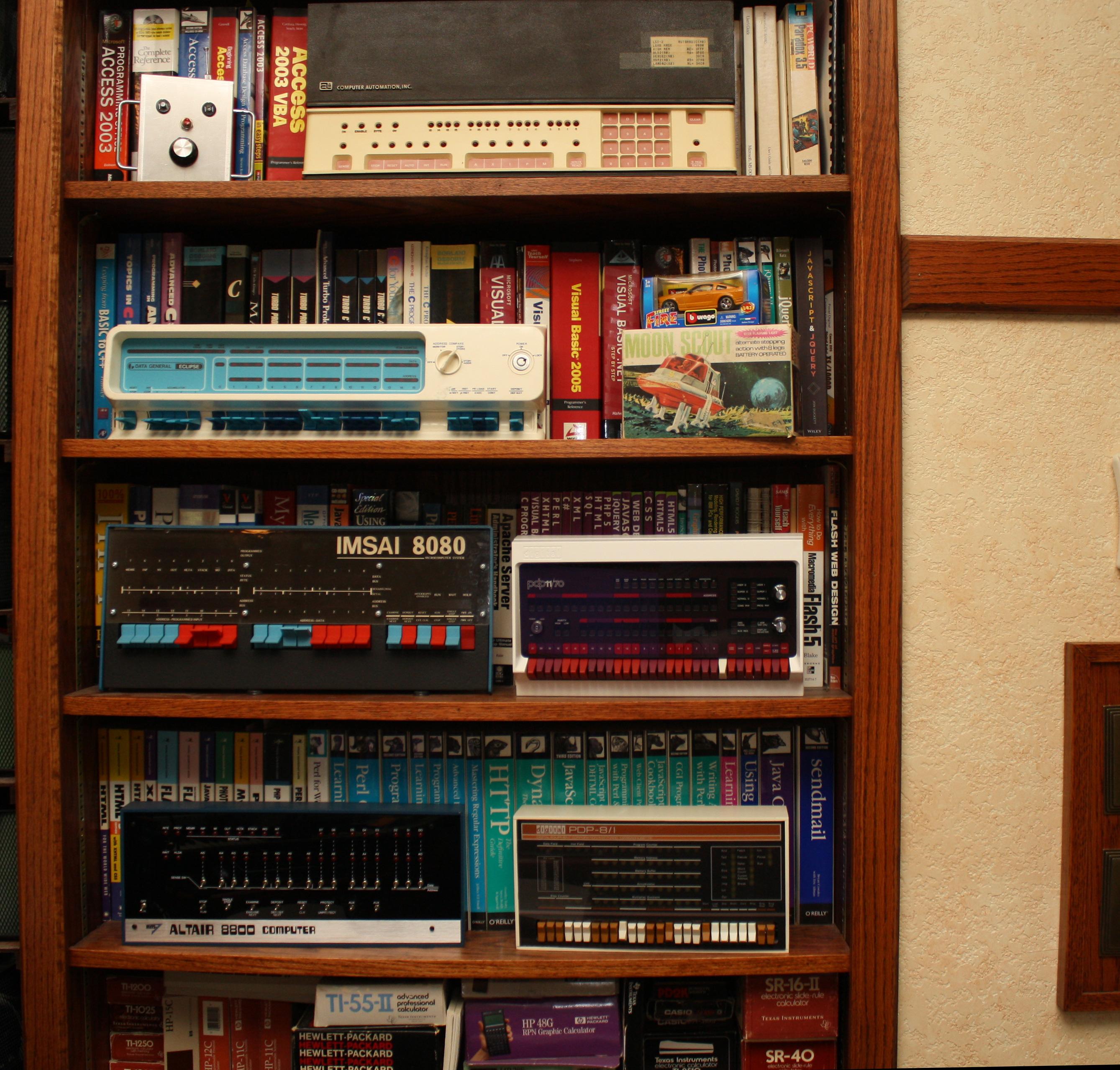
I just spotted one of those Computer Autimation Alpha LSI/02s on e-bay:
https://www.ebay.com/itm/232664722019
No affiliation with the seller, I just thought it might be of interest.
Mark
On 10/19/18 4:48 AM, Nick Sargeant wrote:
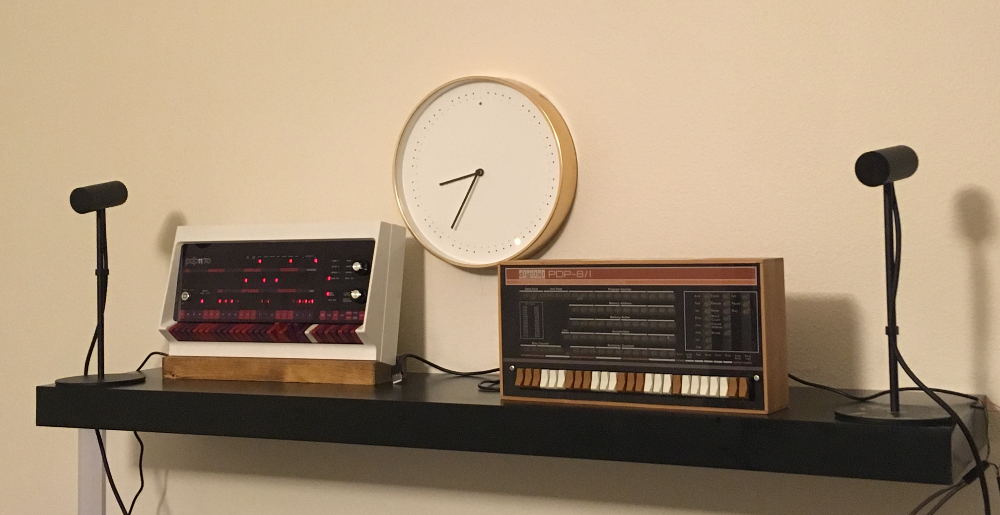
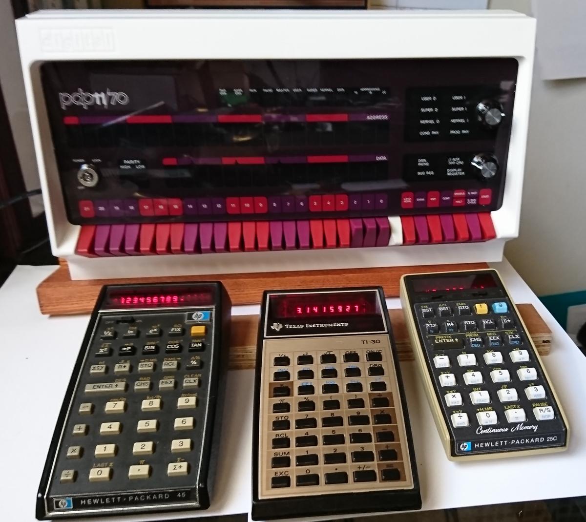
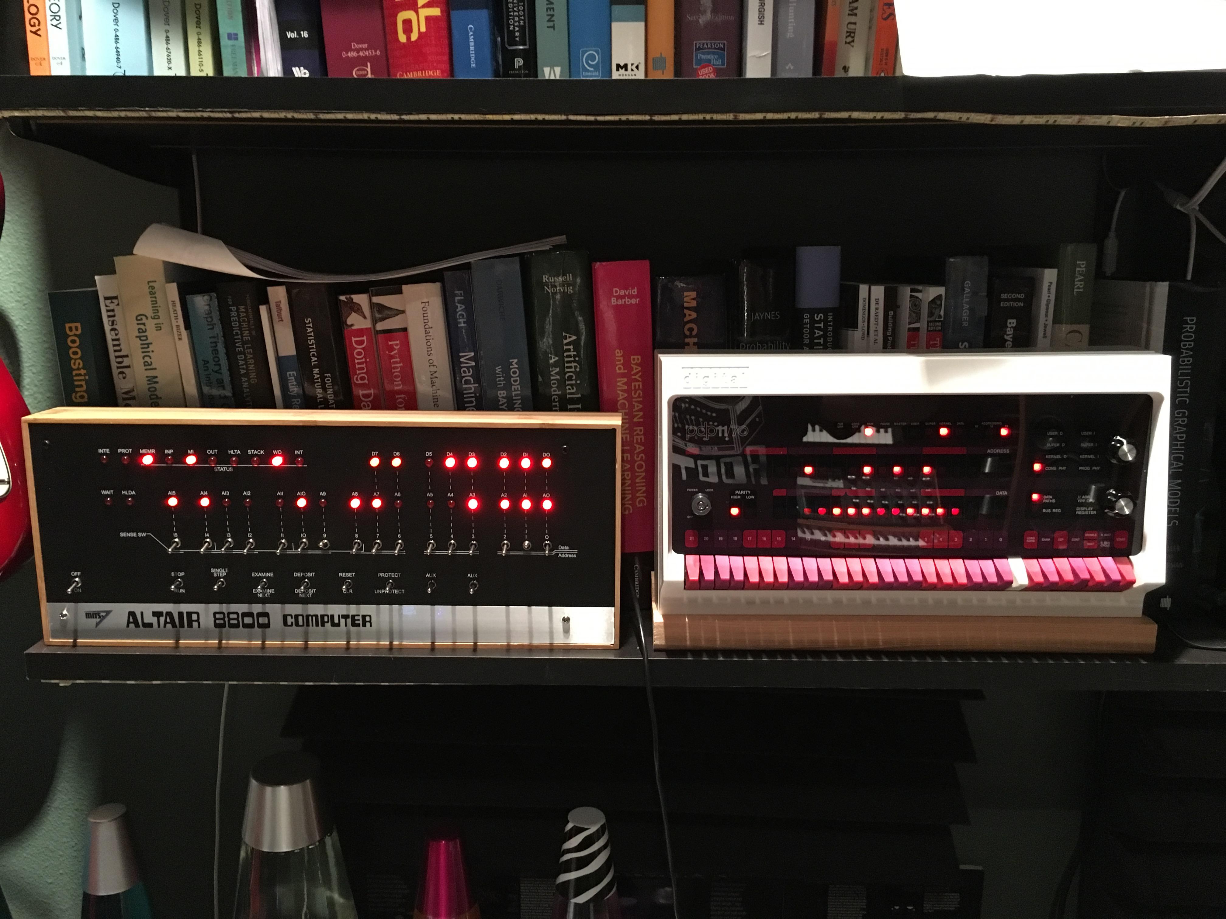
The one on the top shelf is a Computer Automation Alpha LSI/02 or similar. My final year project in 1977 at Uni was to make a student-friendly interface for it that would allow students to plug their projects in to it without risk of damage to its bus. Haven't ever seen one since, but its little orange keys are iconic.
On Wednesday, 17 October 2018 21:03:46 UTC+1, Roger Arrick wrote:
Shelf of glory :)
--
Stephen Casner

dst...@barossafarm.com
Neil Higgins

Justin Sabe

Mike Ferrara


Julian Calaby


Leigh Klotz, Jr.
Stephen Casner
> - I'm still confused about how the power switch works though -- I
> hooked it to the soft switch but I'm not able to predict what will
> happen when I turn the switch...I'd really like it to be a safe RPI
> shutdown. I've read
> http://obsolescence.wixsite.com/obsolescence/pidp-11-connectivity-options
> and maybe the "ON" position is what shuts it down? Not sure...
needs to be for the software as it stands. The switch closes when in
the clockwise position. The "secret" method of shutting down the
simulation is to set HALT and then push in the address display
selection switch. Since that switch is normally open but closes when
pushed, the software needed to take that closure as the signal to shut
down. When the key switch is wired to the "soft keyswitch option"
then the two switches are in parallel. Turning the key switch to the
clockwise position (which would be "POWER" if you have oriented the
two positions to "OFF" and "POWER") is the same as pushing the address
display selection switch. That's backwards, so the software needs to
change for the key switch to make sense. I've been planning to do
this but have not done it yet.
> - I was confused by the 3 screws for the RPI but it seems sturdy
> enough.
West in August. My kit contained 5 standoffs, nuts and screws. I
don't know why 5 since 4 seems the right number, but it was fortunate
because one of the nuts had no threads cut.
> - Does the service have to run as root? I think I remember the
> PiDP-8 doesn't run simh as root.
(simh) does not, even though the pidp11.sh script does start the
client using sudo.
-- Steve
oscarv
>> Turning the key switch to the
>> clockwise position (which would be "POWER" if you have oriented the
>> two positions to "OFF" and "POWER") is the same as pushing the address
>> display selection switch. That's backwards, so the software needs to
>> change for the key switch to make sense. I've been planning to do
>> this but have not done it yet.

Stephen Williams
The front my PiDP-11 looks like everybody else's, so no pictures.
This is achieved with a couple of bits of scrap wood for the housing and one of these:
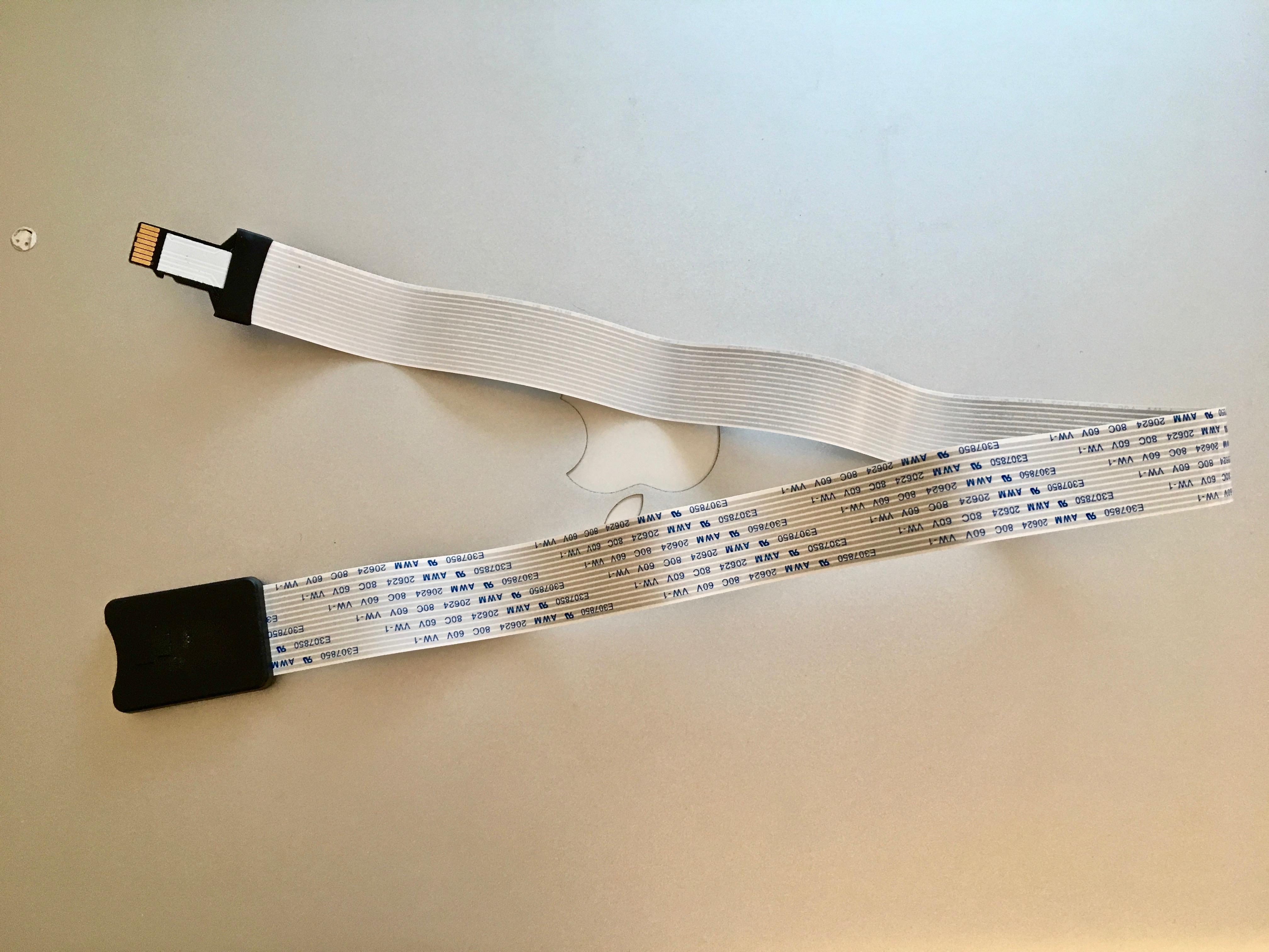
They're available on Ebay and ship from Hong Kong at a pretty reasonable price. You can choose between different end designs, so you could use a full sized SD card if you wished.
I did the same on my PiDP-8, where it's a bit easier to mount by cutting a slot in the wooden case.
Just an idea in case anyone else is interested.
Oscar Vermeulen
--
You received this message because you are subscribed to the Google Groups "[PiDP-11]" group.
To unsubscribe from this group and stop receiving emails from it, send an email to pidp-11+u...@googlegroups.com.
To view this discussion on the web visit https://groups.google.com/d/msgid/pidp-11/7958681b-1530-4081-b553-945f3eac5bf9%40googlegroups.com.
For more options, visit https://groups.google.com/d/optout.
Stephen Williams

bmeyer29

carlo.v...@gmail.com

Colin
- I wanted to set up the back panel with a panel-mount microUSB port for power, but adafruit's panel-mount microUSB cables (https://www.adafruit.com/product/3258) don't fit any of the sets of screw holes on the back panel. I don't think it's anything that can't be fixed with a dremel, but wanted to give anyone planning on the same thing a heads-up; for the time being, I screwed the microUSB port into one of the DB-9 punchouts in a rickety fashion.
- this is entirely on me for going off-script and choosing my own serial console solution, but also note that adafruit's "FTDI Friend" (https://www.adafruit.com/product/284) outputs mini-USB rather than microUSB. I didn't, and had to order an adapter afterward. :p
- as with some others, I didn't need to cut down the spacers the Pi was mounted on; their stock length worked just fine.
- Oscar's right, using a stain does wonders for the stand's aesthetics. I only spent about half an hour putting Danish Oil on it and I love the way it looks.
Tom Lake
Panel Mount Extension USB Cable - Micro B Male to Micro B Female
PRODUCT ID: 3258
$4.95
oscarv
Mark Matlock
I recently finished building a second PiDP-11/70 for the Texas house. I could see a number of improvements over the beta kits. The most significant ones are the 5 metal standoffs for the front panel which have much more thread engagement. Also the taller GPIO header is much better as the potential grounding with metal from the Pi is fixed although II kept some tape on it just in case. You previous post about the 1000 ohm resistor on row 0 helped me fix a bit of flakey Led activity that I thought was from switched.
I also ran across a problem I created that I think others might experience as well. This time I did use a small wire brush wheel on a Dremmel tool to remove any oxide from the switch terminals prior to soldering. Also, I tried to minimize heating of the switches. To more quickly get heat to the switch terminal and PCB trace, I found I was melting a dab of solder on the iron which allowed the heat to conduct more quickly to the terminal and thus heat the switch for a shorter time. However in my rush to minimize heating I made three cold solder joints. These bad solder joints sometimes work and sometimes did not. Small additional pressure on the switch would occasionally improve the connection. One of the bad solder joints was on the white test switch which further gave weird symptoms as all lights would flicker on when I hit the left ad address next to it.
So anyone with odd switch issues may want to add a 1K to 2K in parallel with the row 0 resistor. I used a 1.8K that gave me an effective 650 ohms. Also, as you individually test the switches any that are intermittently not connecting,
Check for cold solder joints. Maybe this is obvious to most of the folks here, but it had me scratching my head a bit.
Best,
Mark
oscarv
Lastly, I don't have the exact number but about 1% of people find the row 0 resistor of 1K is insufficient. For now I'll add an extra 1K resistor in the kit in case builders find they need to add it in parallel to make for a lower resistor value. Next year I'll switch over to 820 ohm resistors, there's really no reason not to.
Mark Matlock

Hendrik-Jan Megens
On Tuesday, July 3, 2018 at 1:25:27 AM UTC+2, Neil Higgins wrote:
In eager anticipation of completed PiDP-11s becoming operational, I am creating this thread for “brag” shots and construction stories - analogous to the thread in the PiDP-8 group. -NO- “mine’s biggier than yours” claims, please - we know they are all the same size. But if you do anything innovative or cute, show us!

Mark Fleming
Great kit and great support from Oscar.
Cheers,
~Mark

John Miller
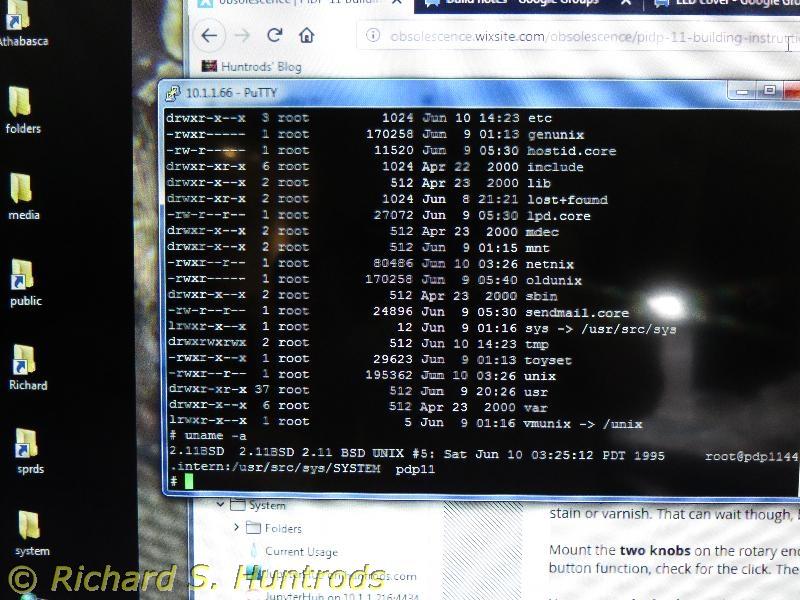
So far just running the default "light show" but I'll be switching to Unix - nostalgia for my first professional software engineering job in 1982, when we had the *source code* (!!!) to AT&T Unix v7m. I spent nights and weekends just reading Unix source code.... Funny that we're still using it, essentially, - and I'm still making a living doing it - via Linux.
-- jdm
Neil Higgins
John Miller
- rubber feet on the front
- a bookshelf divider on the back, fastened to the bottom with 3M Command Strips velcro
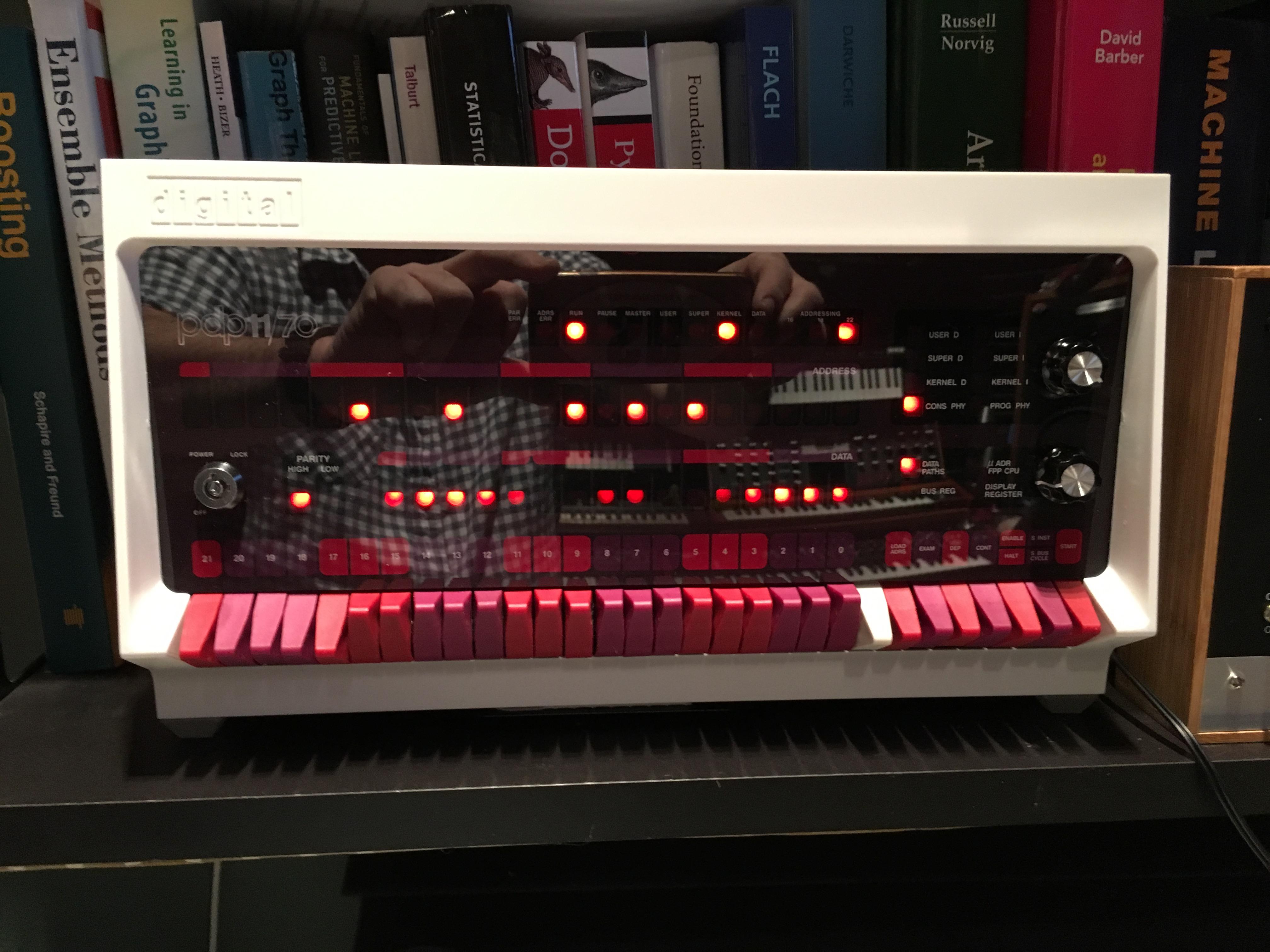
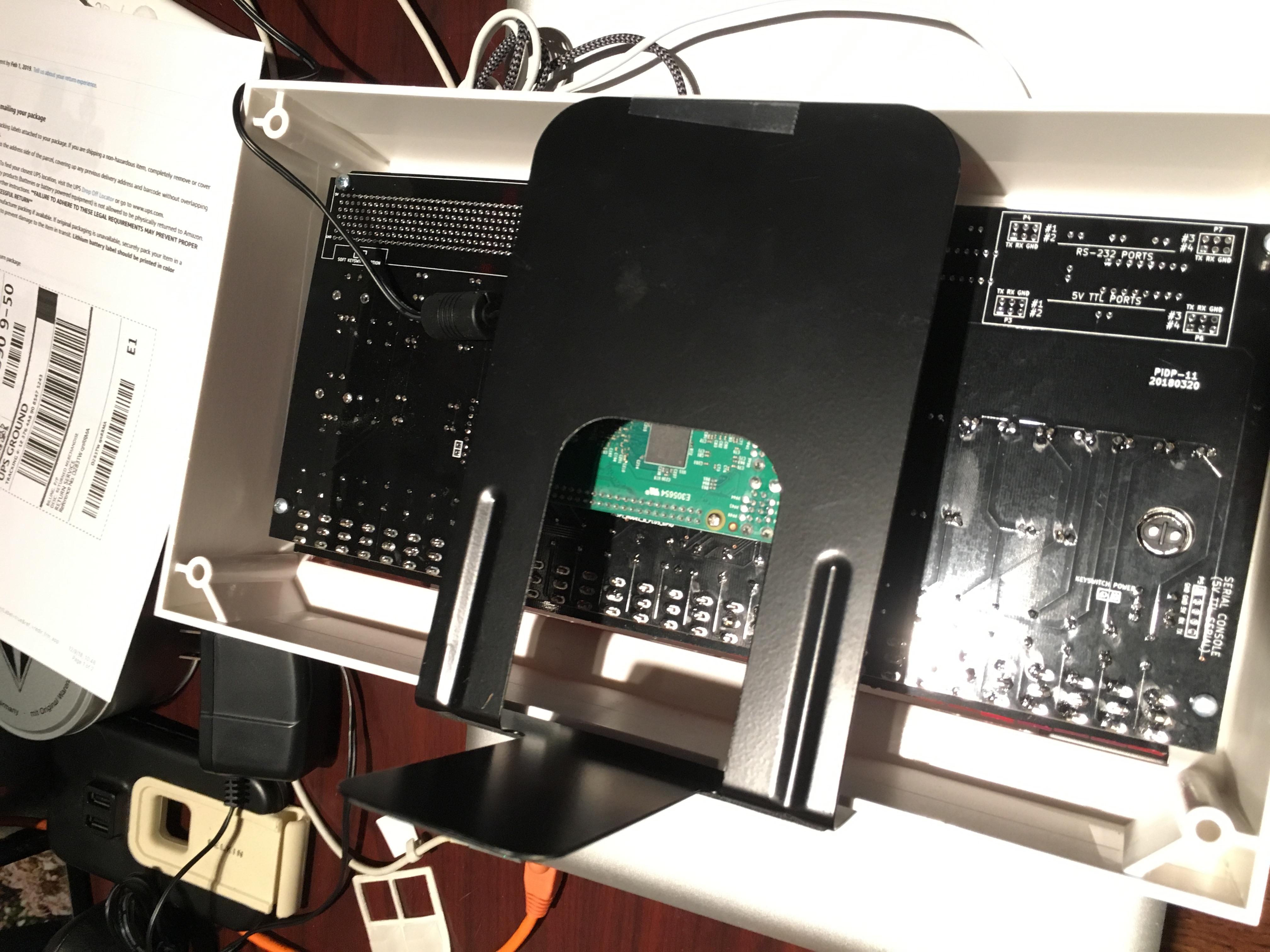
Just attached at the top with Scotch tape at the moment, but I will use another velcro to attach the top of the bookend to the inside top of the pidp case.
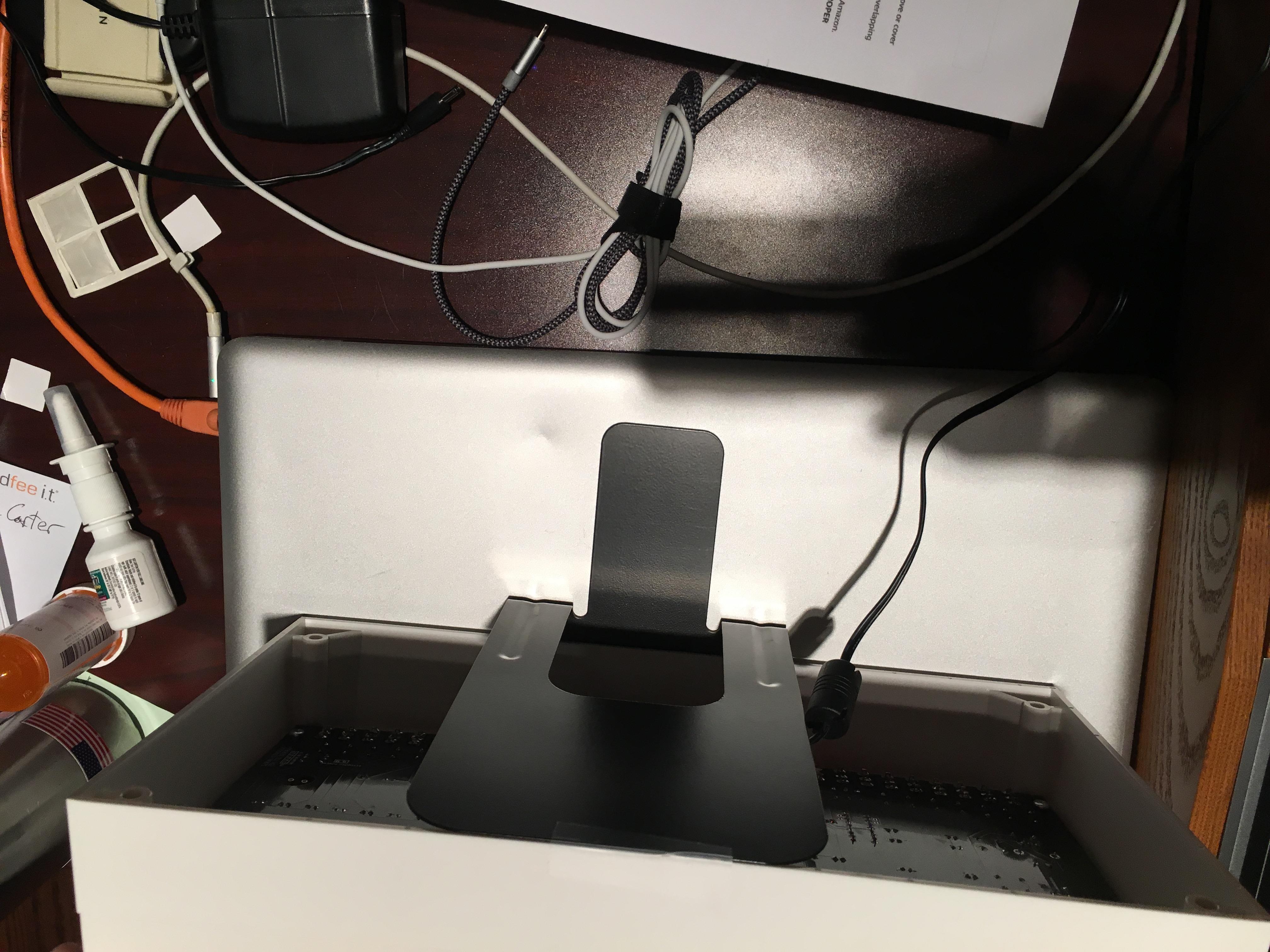
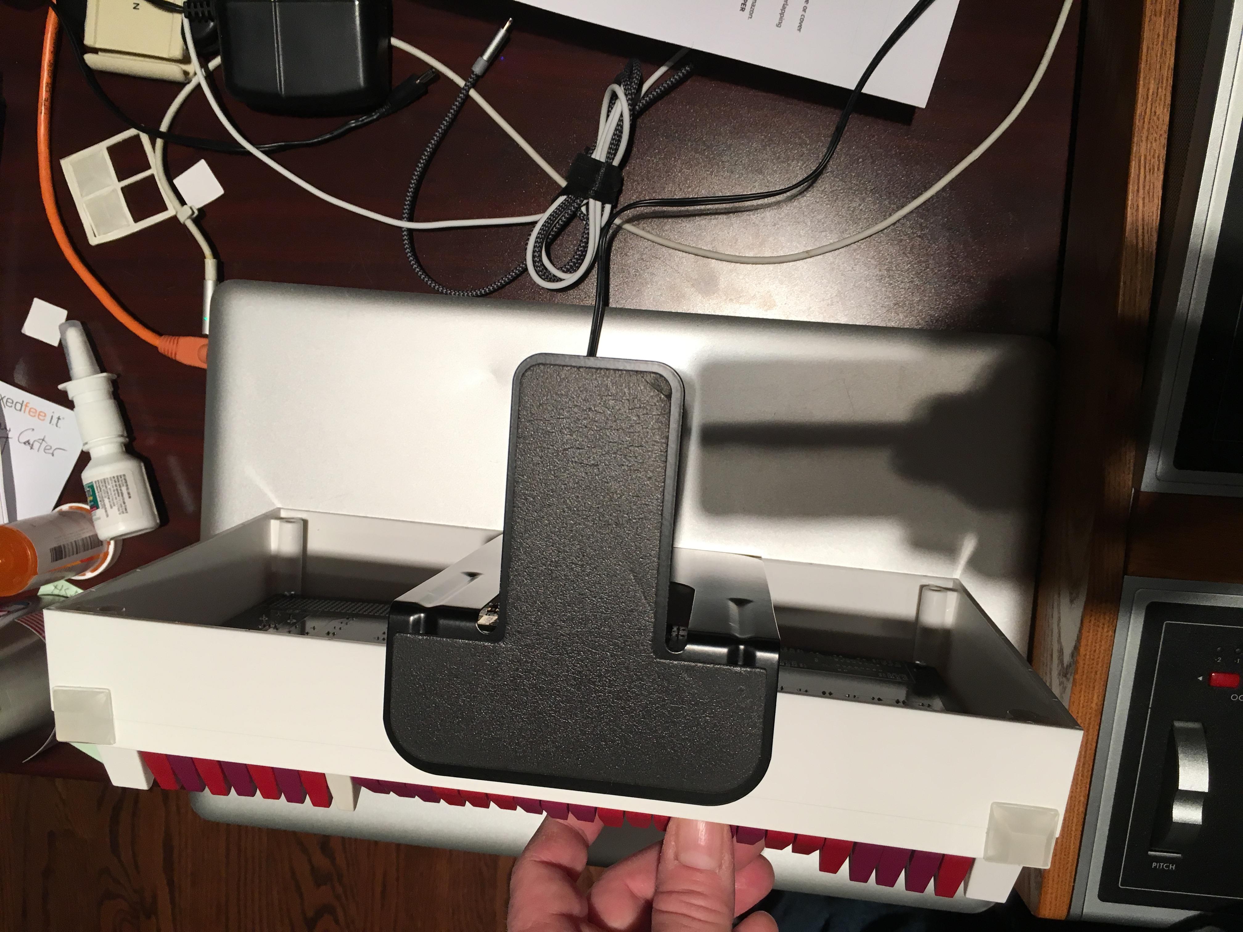
The tongue of the bookend then just slides under the books behind it, and then there's no way it will accidentally fall over. It's not rock-solid as if the pidp was attached to a PDP-11 in a rack, as the bookend is flexible. So, you still have to hold the pidp when flipping switches, but for me for now that's fine.
I got lucky in that a bookend I had lying around was exactly the right height!
John Miller
I tend to associate the pdp11/70 with 1976, as that's when Unix debuted: the July 1976 AT&T Bell Technical Journal. I still have my copy somewhere. But I didn't get "my" first PDP until summer 1982 - actually two pdps, an 11/70 and an an 11/45. I took home the company's mothballed 11/05 and had it in pieces in my apartment's living room, but my then girlfriend (now wife) was not a fan. "But gee, hon, look - real core memory!! And a tape drive!!" SAD!!
Neil Higgins
Tom Lake
Neil Higgins

Chuck McManis
Johnny Billquist
And Unix didn't debute in 1976. There is a reason the Epoch in Unix is
also 1970...
1976 would probably be the sixth edition. Might even be the seventh...
So Altair, and anything else like it, is after the PDP-11.
Johnny
> You received this message because you are subscribed to the Google
> Groups "[PiDP-11]" group.
> To unsubscribe from this group and stop receiving emails from it, send
> an email to pidp-11+u...@googlegroups.com
> <https://groups.google.com/d/msgid/pidp-11/fe94ac6e-4f24-475f-bbbc-bd9b5f73eab2%40googlegroups.com?utm_medium=email&utm_source=footer>.
--
Johnny Billquist || "I'm on a bus
|| on a psychedelic trip
email: b...@softjar.se || Reading murder books
pdp is alive! || tryin' to stay hip" - B. Idol
John Miller
Mark Matlock
oscarv
Mark Matlock
I see what you are talking about. My 60 mm deep wooden frame is exactly the same outer dimension as the back panel and sits in the frame like the back panel. I made the thickness of the wood thick enough that the holes could be drilled so that a longer screw could be used. A common U.S. both size is #10 with 24 threads per inch. A 3 inch long bolt fits pretty well but 2 1/2 inch (I wish we used metric) long 10-24 bolt is the longest common length. The previous one had a 40 mm width and a 2 1/2 inch worked ok. This one I used “all thread” brass rod and cut it with a Dremmel tool.
The biggest problem in my design is that rubber feet need to be added because the flange you are suggesting could be cut off protrudes a bit. What are you thinking of cutting the frame with? A laser cut would be ideal if possible. A mechanical cut might need some polishing. I like working with wood because it is easy to belt sand to close tolerance if you make things a tiny bit oversize.
If the cut were clean on the plastic the attachment could be nicely coupled. You might even want a small square groove in the wood to keep things centered.
I just took a closer look at the bezel and you might only want to cut the outer plastic and leave the stem for the screw intact, but the new box frame would need to be thin. If the stem were cut with the outer shell there is not but stem / bolt hole to screw into.
I also like some of the scaled down rack mount ideas that people have.
Thanks again for a wonderful kit. I really want to get the RSX11M+/Simh/Ethernet software issues solved while on Christmas vacation so we can make a good disk image with everything preinstalled and internet connected.
Best Regards and Merry Christmas,
Mark
oscarv
On Thursday, December 20, 2018 at 1:12:02 AM UTC+1, Mark Matlock wrote:
I see what you are talking about. My 60 mm deep wooden frame is exactly the same outer dimension as the back panel
The biggest problem in my design is that rubber feet need to be added because the flange you are suggesting could be cut off protrudes a bit. What are you thinking of cutting the frame with? A laser cut would be ideal if possible. A mechanical cut might need some polishing. I like working with wood because it is easy to belt sand to close tolerance if you make things a tiny bit oversize.
If the cut were clean on the plastic the attachment could be nicely coupled. You might even want a small square groove in the wood to keep things centered.
I just took a closer look at the bezel and you might only want to cut the outer plastic and leave the stem for the screw intact, but the new box frame would need to be thin. If the stem were cut with the outer shell there is not but stem / bolt hole to screw into.
I also like some of the scaled down rack mount ideas that people have.
Thanks again for a wonderful kit. I really want to get the RSX11M+/Simh/Ethernet software issues solved while on Christmas vacation so we can make a good disk image with everything preinstalled and internet connected.
Mark Matlock
On Wednesday, December 19, 2018 at 6:27:33 PM UTC-6, oscarv wrote:
Mark,
On Thursday, December 20, 2018 at 1:12:02 AM UTC+1, Mark Matlock wrote:I see what you are talking about. My 60 mm deep wooden frame is exactly the same outer dimension as the back panelIn that case, better not chop the PiDP case: it angles out at a 3 degree angle. So if you chop off a bit, the dimensions into which your case fit will be slightly too large!
The biggest problem in my design is that rubber feet need to be added because the flange you are suggesting could be cut off protrudes a bit. What are you thinking of cutting the frame with? A laser cut would be ideal if possible. A mechanical cut might need some polishing. I like working with wood because it is easy to belt sand to close tolerance if you make things a tiny bit oversize.Ah, cutting off the bottom bit would be fine for you case of course.
The local carpenter/furniture maker (the one that does the wood base in the kit) told me he could saw off the back of the case neatly, cleanly, precisely. And that any carpenter could do it.But it's untried & untested so far... I'll send you a new case if the experiment fails ;)
If the cut were clean on the plastic the attachment could be nicely coupled. You might even want a small square groove in the wood to keep things centered.Indeed, that would work nicely!I just took a closer look at the bezel and you might only want to cut the outer plastic and leave the stem for the screw intact, but the new box frame would need to be thin. If the stem were cut with the outer shell there is not but stem / bolt hole to screw into.There is, the stem for the bolt hole is through&through, so if you shorten it in line with the rest of the case it will still hold a screw.
I also like some of the scaled down rack mount ideas that people have.Henk Gooijen really needs to make a kit out of his RK05 enclosure!
Thanks again for a wonderful kit. I really want to get the RSX11M+/Simh/Ethernet software issues solved while on Christmas vacation so we can make a good disk image with everything preinstalled and internet connected.Yes, I have been passive on that front... I was not-so-secretly planning to catch Johnny Billquist at our local VCF last month, but he managed to escape ;)
Henk Gooijen
Many times I have hesitated to start cutting the white frame of Oscar's PiDP-11/70 kit. Still hesitating ...
But I do have ideas how to build a metal box and attach it to the (cut frame) PiDP-11/70 front panel.
I try to work with standard available aluminum profiles, because I am not a "mechanical guy" and I do not have access to fancy machine tools.
I think that using "Z" profiles and metal plates is all you need (plus "L" profiles on the corners to make the box sturdy).
Why "Z" profiles? Simple: the box must be smaller than the front else it would not fit *in* a rack.
The RK05 is complex. Making a *kit* of that will be a *lot* of work.
Now working on a (working) mechanism for the door lock.


Roy Simkins
--
You received this message because you are subscribed to the Google Groups "[PiDP-11]" group.
To unsubscribe from this group and stop receiving emails from it, send an email to pidp-11+u...@googlegroups.com.
To view this discussion on the web visit https://groups.google.com/d/msgid/pidp-11/66b12ae2-5da1-4c80-9c1e-d66fb3056a06%40googlegroups.com.
Hendrik-Jan Megens
Tom Lake

Bob Flanders
terry-...@glaver.org
In eager anticipation of completed PiDP-11s becoming operational, I am creating this thread for “brag” shots and construction stories - analogous to the thread in the PiDP-8 group. -NO- “mine’s biggier than yours” claims, please - we know they are all the same size. But if you do anything innovative or cute, show us!
Stephen Casner
So, it turns out you actually *can* get the back panel on, with a reasonable complement of connectors, if you're creative. I wound up trimming off the strain reliefs on both the Ethernet and micro USB extensions from Adafruit, and had to go even further and trim off some of the injection molding on the back of the Ethernet extension.

sunnyboy010101


Peter Viscarola