Back to Steinway L with heavy action, many leads

Encore Pianos

It will still be a couple of weeks before I get back up to pick up the action on the finger busting Steinway L that has been the subject of much discussion, but a couple of questions have occurred to me about the shanks. I have pretty much decided that I will replace the shanks (instead of replacing knuckles) on this beast, going to the 17 mm. spread on the knuckles from the 15.5 mm. Renner shank that is on the piano now.
Whether it is a Renner, Tokiwa, or Abel iteration, it would seem that the Hamburg 17 mm. shank is not the best choice of what is available. As best I can gather, the distance from the center of the screw hole in the flange to the center pin is 24 mm., whereas the Renner sample shanks I have in my shop at the 15.5 spread are about 23 mm. Since the discussion about using the 17 mm. shank has also spoken to the need to shim the whippen flange away from the rail by 1 or 2 mm. in order to maintain alignment of the jack with the core, it would seem that the Abel Encore E NYS -10 or Abel Encore E NYS -11 would be better suited as a replacement, since the hole to center pin distance is 23 mm, along with the 17 mm. spread from the knuckle to the center pin. Otherwise I would have to shim the whippen flange another 1 mm. on top of whatever the use of the 17 mm. knuckle spread already requires. Unless I am misunderstanding something, either of the Abel shanks are the better choice for this reason.
Which brings me to my next question: The NYS-10 and the NYS-11 designate the size of the knuckle – a 10 mm knuckle and a 11 mm. knuckle respectively. Which knuckle size would be better suited to this piano? If I move the capstan towards the balance rail pin by say 2 mm in order to better the key ratio AND use the 17 mm. knuckle, it seems that key dip will increase towards the outer limits of “acceptability”, as in the neighborhood of 11 mm plus. I’m not clear as to which knuckle size will be best suited to my circumstance and have the lesser impact on the dip.
Any further clarification would be appreciated. Thanks.
Will Truitt
Ron Overs

It will still be a couple of weeks before I get back up to pick up the action on the finger busting Steinway L that has been the subject of much discussion, but a couple of questions have occurred to me about the shanks. I have pretty much decided that I will replace the shanks (instead of replacing knuckles) on this beast, going to the 17 mm. spread on the knuckles from the 15.5 mm. Renner shank that is on the piano now.
. . . Which brings me to my next question: The NYS-10 and the NYS-11 designate the size of the knuckle - a 10 mm knuckle and a 11 mm. knuckle respectively. Which knuckle size would be better suited to this piano?
--

Dale Erwin
, going to the 17 mm. spread on the knuckles from the 15.5 mm. Renner shank that is on the piano now.
I logical choice
Whether it is a Renner, Tokiwa, or Abel iteration, it would seem that the Hamburg 17 mm. shank is not the best choice of what is available. As best I can gather, the distance from the center of the screw hole in the flange to the center pin is 24 mm., whereas the Renner sample shanks I have in my shop at the 15.5 spread are about 23 mm.
This is what I found when looking very closely at mocked up parts next to original specs. One Mm can require a lot of ibuprofen Will. good lookin out there
Since the discussion about using the 17 mm. shank has also spoken to the need to shim the whippen flange away from the rail by 1 or 2 mm. in order to maintain alignment of the jack with the core, it would seem that the Abel Encore E NYS -10 or Abel Encore E NYS -11 would be better suited as a replacement, since the hole to center pin distance is 23 mm, along with the 17 mm. spread from the knuckle to the center pin. Otherwise I would have to shim the whippen flange another 1 mm. on top of whatever the use of the 17 mm. knuckle spread already requires. Unless I am misunderstanding something, either of the Abel shanks are the better choice for this reason.
I agree
Which brings me to my next question: The NYS-10 and the NYS-11 designate the size of the knuckle – a 10 mm knuckle and a 11 mm. knuckle respectively. Which knuckle size would be better suited to this piano? If I move the capstan towards the balance rail pin by say 2 mm in order to better the key ratio AND use the 17 mm. knuckle, it seems that key dip will increase towards the outer limits of “acceptability”, as in the neighborhood of 11 mm plus. I’m not clear as to which knuckle size will be best suited to my circumstance and have the lesser impact on the dip.
Typically I only use 10mm knuckles,...SO I can't speak to the change an 11 would make except that the capstan will need to be lowered further in the key to get the hammer line down to rational blow distance. This may move the wip heel/capstan line into or out of compliance. I'd mock it up and regualte some notes really closely and observe the differences best you can.
Dale
Any further clarification would be appreciated. Thanks.
Will Truitt
Encore Pianos
Hi Ron:
I won’t be able to short bore these hammers without plugging them and starting over. If I do that, I might as well get a lighter hammer instead of these Renner Blues that I am choosing to work with – which would have been the better choice to match the original set up. There is little wear on these hammers, since she has pretty much not played it all these years, and by some miracle the bore distance is substantially correct. I’ll do a full side taper and more coving on the Blues to put them on a diet after I pop them off the shanks before remounting them
Thanks for the comment about the friction being better with the smaller knuckle, so the 10 mm. will be better for this piano.
When you talk about the key ratio dictating dip, are you talking about me setting up my test notes to a dip of say 10 mm. and a blow distance of say 45 mm., then moving a capstan forward or back on top of the key, until the jack just clears the knuckle at check? If not that, what are you referring to?
I won’t be changing whippens, but one of my options is relocating capstans and moving the capstan heels to accommodate that. Probably the whippens will be moved back, in order to line up the jack better with the knuckle core on the 17 mm. shanks.
Will
Encore Pianos
Hi Dale:
One thought I have had is that, if I am knocking off the capstan heels to move them if I move the capstan towards the balance rail to improve the key ratio, I can also check my half stroke line and modify the thickness of the heel to meet the half stroke line from the whip center pin to the bottom of the key at the balance rail pin while I have them off.
The 10 mm. knuckle it will be.
Thanks, Dale
Will Truitt
From: pian...@googlegroups.com [mailto:pian...@googlegroups.com] On Behalf Of Dale Erwin
Sent: Tuesday, April 02, 2013 7:04 PM
To: pian...@googlegroups.com
Subject: Re: [ptech] Back to Steinway L with heavy action, many leads
, going to the 17 mm. spread on the knuckles from the 15.5 mm. Renner shank that is on the piano now.
Dale Erwin

Isaac OLEG
The lines of centre are to be taken with a pinch of salt, if you consider the bending of parts.
As perfect ratio eveness between sharps and white keys , some may consider that due to the mechanical advantage given by the higher key surface, a slightly higher ratio is accepteable.
(I am not persuaded of that one but too easy sharps are not so pleasing. Not easier to play than a white key played a little far from the edge)
The 11 mm dimension is probably the large dimension, which is necessary on original Steinway whippens.
That 1mm loss on spread is documented since 10 years at last I fall of my chair when reading you discovering it.
On the pianotech forum I have tried to discuss about its consequences with an absolute silence as a result. (only the usual self promotion)
back to my brodery work soon.
On an old Steinway the keyboard have strong leverage generally , you may wish to use that as an opportunity
as you can correct the spread move the stack and glue
the hammer 131 or 132 mm if necessary
The smaller hammer are there to avoid blocking ay Ffff.
Allowing small letoff then.
I Cant understand why The tone difference between 90 and 91-92 rake is so much noticed, and visibly I will not know that before some time.
Poroblems with jack button wear goes along with the wedging effect of the action that is accumulating energy during the stroke before the jack provide the last motion by itself.
If the action would be direct and rigid it would be unplayeable.
As friction depends of the leverage, I am not persuaded there is less at the end of the motion with a 9 mm roller.
Symetry and material resistance are parts of piano design certainly, but what counts is the musical result, there are gross mistakes caused by tradition , but gross mistakes caused by design and engineering as well.
By cleaning the tone ans suppressing defects, it is possible to obtain a somewhat boring and predicteable tone.
I guess that the different parts of what gives the "imprint" of a brand in the tone of their pianos , plate resonance, soundboard parasitic behaviour, case filtering the tone, and many others are what allows the piano to go out of control , hence giving the impression to be lively.
Encore Pianos
I am a bit unclear as to what your intentions are in moving the stack, presumably towards the key end of the frame. I don't see how that would correct the spread, if we are talking about the distance of the whip center pin from the hammer shank center pin. As you know, that position is fixed on Steinways by the rails being soldered on the action frame, whether right or wrong when set up. That could not be changed without shimming the whippen rail to move the whole whippen and its center pin a defined measure away from the hammer shank center pin to achieve the desired spread. It would seem that the only relationship that changes with moving the stack would be to change the relationship of the capstan and the whippen EA. Presumably you are relocating the hammer further out on the shank at 131 or 132 mm to re-establish the proper strike line.
Would there be any value in shimming up the hammer shank flange a mm. or 2 at the rail, assuming adequate clearance of the drop screws and hammers under the stretcher entry, in concert with other changes?
Will
-----Original Message-----
From: pian...@googlegroups.com [mailto:pian...@googlegroups.com] On Behalf Of Isaac OLEG
Sent: Wednesday, April 03, 2013 5:06 AM
To: pian...@googlegroups.com
Subject: Re: [ptech] Back to Steinway L with heavy action, many leads
Ron Overs
>I won't be able to short bore these hammers without plugging them
>and starting over. If I do that, I might as well get a lighter
>hammer instead of these Renner Blues that I am choosing to work with
>much not played it all these years, and by some miracle the bore
>distance is substantially correct. I'll do a full side taper and
>more coving on the Blues to put them on a diet after I pop them off
>the shanks before remounting them
boring job on a hammer est once they have been tapered.
> When you talk about the key ratio dictating dip, are you talking
>about me setting up my test notes to a dip of say 10 mm. and a blow
>distance of say 45 mm., then moving a capstan forward or back on top
>of the key, until the jack just clears the knuckle at check? If not
>that, what are you referring to?
most techs who say they are setting 10 are mostly setting it a little
deeper. I remember once in 1992 a certain overseas technician was
showing us all how reg is done, here in Sydney, and he set the dip
which I later checked and found it to be almost 11 mm. I've found
that more pianists start to complain about 10.5, but hardly any
complain about 10.25 provided that one is quite particular to ensure
that no keys are even a little bit over.
I have a series of small blocks which can be taped to the wippen to
act as dummy heels, along with a short shanked capstan (sawn off),
set in a shallow block. The capstan can be moved and checked with
various heel blocks until the appropriate position is found for the
optimum ratio with minimum friction.
> I won't be changing whippens, but one of my options is relocating
>capstans and moving the capstan heels to accommodate that. Probably
>the whippens will be moved back, in order to line up the jack better
>with the knuckle core on the 17 mm. shanks.
repetition (balancier) slot to line it up with the knuckle tongue
without moving the wippen. It will mean that the jack tail will be a
little higher in the rest position, but it won't make that disaster
much worse. Furthermore, moving the wippen back will raise the action
ratio a little (assuming that you will be moving the heel/capstan
anyhow).
I really enjoy setting the action geometry with each rebuild. Once
one is used to the process, each action seems to turn out almost the
same in terms of touch and control.
The other matter which very often requires attention is that the
damper lever tray is invariably mounted too high relative to the
keys. With Steinway Ds we usually have to lower the damper tray
between 3 and 4 mm to minimise friction between the damper lever and
the key (a new set of mounting blocks is the usual fix here). Notice
with the factory standard setup that the levers gouge a hole in the
lift felt after only a few years use. This is another friction source
that has no positive benefit to the function of the action. This
relationship can be checked on the bench by clamping the damper
system to the bench top, and running the action under the levers to
observe the relationship. It makes one wonder how many of the factory
guys are paying attention to this stuff.
Isaac OLEG
Encore Pianos
Thanks for the heads up on the dip measure. Most of the simulations I have
done in Nick's program where I use the 17 mm. shank and move the capstan
around 2 mm towards the balance rail are banging into just shy of 11 mm.,
unless I reduce hammer blow distance by several mm. I'm still ending up
around 10.5 mm, even when I split the difference between reducing hammer
blow and increasing dip. Only changing the shank from 15.5 to 17 mm sets
the dip at 10.92 with an action ratio of 6.09 to 1, moving the capstan 2 mm.
leaves dip at 11.12, action ratio at 5.98 to 1. (both sets of figures
without modifying blow distance) It seems likely then that I will be
settling for an action ratio above 6 to 1 in order to have better dip
values.
I won't be pulling the tray on this job. That may be for another day.
Out the door for tunings now.
Will
-----Original Message-----
From: pian...@googlegroups.com [mailto:pian...@googlegroups.com] On
Behalf Of Ron Overs
Isaac OLEG
Isaac OLEG
Le mercredi 3 avril 2013 13:01:34 UTC+2, Encore Pianos a écrit :
Hi Isaac:
I am a bit unclear as to what your intentions are in moving the stack, presumably towards the key end of the frame. I don't see how that would correct the spread, if we are talking about the distance of the whip center pin from the hammer shank center pin. As you know, that position is fixed on Steinways by the rails being soldered on the action frame, whether right or wrong when set up. That could not be changed without shimming the whippen rail to move the whole whippen and its center pin a defined measure away from the hammer shank center pin to achieve the desired spread. It would seem that the only relationship that changes with moving the stack would be to change the relationship of the capstan and the whippen EA. Presumably you are relocating the hammer further out on the shank at 131 or 132 mm to re-establish the proper strike line.
Would there be any value in shimming up the hammer shank flange a mm. or 2 at the rail, assuming adequate clearance of the drop screws and hammers under the stretcher entry, in concert with other changes?
No it does not correct the spread but as you said the whippen lever , then the ratio is reduced. shimming the flange you raise it, and it may be advantageous to move the stack the other direction then. , but lat time I tried I have seen that I needed both. could regulate at 45 mm and 10.25 max, but that was just luck because of the keyboard allowed that.
Isaac OLEG

David Love
An AR of 6.09 and a blow distance of 45 mm should produce a dip of
approximately 9.64 mm.
AN AR of 5.98 with the same blow distance should result in a dip of
approximately 9.77 mm.
Even if you increase the blow to 48 mm, at 5.98 AR the dip would only
increase to approximately 10.28 mm.
Your dip numbers are too high for the AR's that you are using. To get an AR
of 5.98 to yield an 11.12 dip, my calculations indicate you would have to
increase the blow distance to something like 53 mm. Of course, that's far
too much.
David Love
www.davidlovepianos.com
David Love
David Love
www.davidlovepianos.com
David Love
David Love
www.davidlovepianos.com
Dale Erwin
The lines of centre are to be taken with a pinch of salt, if you consider the bending of parts.
As perfect ratio eveness between sharps and white keys , some may consider that due to the mechanical advantage given by the higher key surface, a slightly higher ratio is accepteable.
(I am not persuaded of that one but too easy sharps are not so pleasing. Not easier to play than a white key played a little far from the edge)
The 11 mm dimension is probably the large dimension, which is necessary on original Steinway whippens.
That 1mm loss on spread is documented since 10 years at last I fall off my chair when reading you discovering it.
On the pianotech forum I have tried to discuss about its consequences with an absolute silence as a result. (only the usual self promotion)
back to my brodery work soon. Whats this?
Dale Erwin
David Love
Isaac OLEG
Ron Overs
>if I am not mistaken, moving the wippen back, increasing the spread
>and lengthening the input arm, will lower the AR.
capstan are not changed. But when the heel/capstan contact position
will be reset, the effect on it (from a ratio perspective) drops out
of consideration. However, the leverage length between the wippen
centre and the jack/knuckle contact will be increased, which will
raise the ratio of the upper stack (to slightly undo the good work
which was achieved by using 17 mm shanks).
While the distance between the balance pin and the wippen-flange
centre will also be increased, this should be of little concern to us
at this point, since the capstan/heel contact will be shifted to
whatever position is necessary to achieve the overall ratio between
the key and the hammer that we require for proper action function.
The other matter to consider, with moving the wippen back, is that
the line of centres will be moved up further away from the
jack/knuckle contact, so that the line becomes even further away from
the contact point to raise friction between the jack and knuckle. One
of the significant changes I designed into my own grand action was to
shorten the length of the wippen-flange-to-jack-centre distance (back
from 99 mm in a standard action to 75 mm), specifically to move the
centre line (wippen centre to hammer flange centre line) closer
towards the jack/knuckle contact point to reduce friction. Moving the
wippen back will increase jack/knuckle friction. This is why I would
advise caution about doing this.
The 17 mm shanks will move the ratio in the direction Will wants to
go, which will reduce the required capstan position shift.
I also agree with your recent post re the ratio implications for the
dip and blow distance, as Dale does also. But further to your
comments, I don't believe we should even consider setting these
figures outside the normal settings, which for me has settled at
10.25 dip and 45 blow distance. I will use a different blow distance
on occasions but I have come to consider the 10.25 dip as non
negotiable, unless a client asks for something different. With 17 mm
shanks and standard action lever lengths for other parts of the
action stack, the capstan/heel contact position can be adjusted to
achieve an excellent result every time. My judgement of the optimum
ratio is determined by the position of the jack relative to the
knuckle at the check point (as I've mentioned in earlier posts).
I hope this all makes sense to you David. If you have a different
view re any comments above, I'd be interested to hear since I value
your analytical capabilities.
Regards,
David Love
capstan move and the heel move are separate considerations. If the capstan
is moved that will change the key ratio and the overall ratio as that is one
of the multipliers, we agree on that. It will also change the wippen ratio
because of where the capstan now contacts the wippen relative to the wippen
center, changing the input arm on the wippen. It will not change the output
arm. So far so good. Let's assume no elevation changes.
However, relocating the wippen heel in and of itself will not change
anything in terms of action ratios as that will not change the input or the
output distance, only the contact point on the heal itself. Imagine that
you elongate the wippen on one side so that the capstan would now be
centered underneath it without moving the capstan. Nothing in the action
ratio will change. Taking the heel off and moving it is a simple
repositioning to center the capstan underneath it.
In this case, the first move is from 15.5 to 17 mm knuckle increasing the
length of the input arm on the shank, thus reducing the shank ratio and the
ratio overall. Then, the capstan move will be toward the balance pin
shortening the output arm of the key, lowering the key ratio and the action
ratio overall even more. That move will also lengthen the input arm of the
wippen with even more lowering of the ratio (more bang for the buck with a
capstan move). Increasing the spread will again lengthen the input arm of
the wippen reducing the overall ratio, hopefully to a desired level
(convergence issues notwithstanding but you addressed those concerns).
Moving the heel then to center it over the capstan won't do anything, other
than center it over the capstan. It will not change the length of any input
or output arms on any of the levers.
Let's hope that the original calculation of the action ratio at 6.7 is
correct otherwise after all that the piano will be regulating with 12 mm of
key dip.
Behalf Of Ron Overs
Sent: Wednesday, April 03, 2013 11:46 AM
To: pian...@googlegroups.com
Subject: Re: [ptech] Back to Steinway L with heavy action, many leads
Isaac OLEG
How long is the flange to jack measure ?
Using 17 creates similar situation than undercentering (let off occur farther under the line) the hammer should be bored 89 and action should slant more hence the need for smaller bore possible
If you could have letoff above the strings it would be very pleasing.
I dont shim more than 1 mm but I would if it could be done without stressing the flange. Yet with 1 mm it can bend .)
and because the less firm fixing of the flange is perceived (the flange also can turn easily)
The relation between jack rotation and knuckle at some point is too bad and knuckle will flatten in time. (sometime it works "as it is" because the jack can be left centered under the knuckle.
Knuckle is 12 mm large, while Abel sells also 11 mm large , too small (I have pics somewhereľ ľ
Possibly they sell 11 mm diameter knuckle. Never seen them on a Steinway (once, on a Foerster of the 60 s.
Smaller spread put the jack top farther from the line of centers. I do not get the comment
The best would be to use shanks with the 23 mm dimension and 17 mm.
Encore Pianos
I have no reason to doubt your numbers, particularly since there seems to be
general agreement that something in the numbers I have given you is amiss.
I'll take your word on that, my use of Nick's action geometry program is
pretty new. I suspect operator error, although I will have to go back and
figure out what I have done wrong in my inputs that leads to these values.
I threw them in quickly this morning at about 6 AM. (When all else fails,
read the directions.) So if there is any cabbage chucking going on, please
aim at me and not Nick or his program.
I've been out tuning all day and I will be running out shortly for the rest
of the evening. So most of this will have to wait.
When I do finally get her action into the shop, I will be very meticulous in
my measurements and analysis. The figures given were gathered in her home
while I was talking with her, and I will want to confirm that what I have is
correct, as well as add to it.
Thanks again to all of you, you continue to flesh out my knowledge of this
very interesting and complex subject.
Will Truitt
Dale Erwin
my measurements and analysis. The figures given were gathered in her home
while I was talking with her, and I will want to confirm that what I have is
correct, as well as add to it.
Thanks again to all of you, you continue to flesh out my knowledge of this
very interesting and complex subject.
Will Truitt
David Love
Send me the measurements you got for each lever input and output, and where
you measured from and I'll put it in my spreadsheet and check it, although
mine is basically the same as Nick's, I've just done it on an excel
spreadsheet.

Ron Nossaman
> Will:
>
> Send me the measurements you got for each lever input and output, and where
> you measured from and I'll put it in my spreadsheet and check it, although
> mine is basically the same as Nick's, I've just done it on an excel
> spreadsheet.
them to the list and see what comes back.
Ron N
Isaac OLEG
David Love
David Love
www.davidlovepianos.com
Encore Pianos
In a private conversation by e-mail, David pointed out to me an important
omission that I left out as this wonderful discussion has proceeded: All of
the measurements that I took and input into the action geometry program were
by the Simple Horizontal Method. The places at which I took my measures
were:
Key Ea measured from front of key to center of balance pin at punchings
(both measures taken at bottom of key in horizontal plane) Measure is
235.68 mm.
Key Ra measured from center of balance pin to perpendicular line which
passes through center of capstan top (perpendicular line scribed to bottom
of key, both measures taken a bottom of key in horizontal plane). Measure
is 115.71 mm.
Whip Ea measured from the whip center pin to a line perpendicular to the
contact point of the whippen heel/capstan contact point, (in horizontal
plane). Measure is 61.17 mm.
Whip Ra measured from the whip center pin to the jack center pin. Measure
is 98.75 mm.
Shank Ea measured from the hammer flange center pin to the center of the
knuckle core. (in horizontal plane). Measure is 15.5 mm.
Shank Ra measured from the hammer flange center pin to the center of the
hammer molding. (in horizontal plane). Measure is 130.6 mm.
Nick's program reported:
Action Ratio of 6.65 to 1
Force Leverage of .15 to 1,
Key Ratio of 2.04 to 1
Whippen Ratio of 1.61 to 1
Shank Ratio of 8.43 to 1
A downweight of 50 grams will balance a hammer weight of 7.50 grams
A keydip of 10 mm. will yield a total hammer rise of 66.5 mm
I recognize now that many of you typically measure by the Theoretical or
Alternate Lever Arms method. This will give you different values than the
horizontal method, and may well have colored the advice you have given me in
a somewhat different direction. If so I apologize for diminishing the value
of your offer by my unwitting (or witless, depending on your point of view)
use of the horizontal method, without properly disclosing it to you.
Changing only the Shank Ea by installing a 17 mm knuckle to replace the 15.5
mm, changes the action ratio to 6.09 to 1, and the key dip increases to
10.92 from 10 mm (in the simple horizontal method). And this is where
things begin to diverge from what others are calculating. But I think I am
beginning to understand why the discrepancy is there. In the simple
horizontal method, the whippen Ra will not change as the knuckle placement
moves. That remains a fixed measure from the whip center pin to the jack
center pin that is unaffected by changing the knuckle placement. By
contrast, whippen Ra in the alternate lever arms measure is taken from the
whip center pin to the back of the jack when it is lined up with the back of
the knuckle core, ideally where the two form a straight line. Moving the
knuckle means that the back of the knuckle core has moved about 1.5 mm if we
go from 15.5 to 17 mm., and presumably our measure of the whip Ra in the
alternate lever arm method will change by roughly that 1.5 mm (shorter), if
we are lining up the back of the jack with the back of the knuckle core.
That will change the whippen ratio. If I had all of the alternate lever
arms measures, I could make calculations that would reflect the differences
that others are finding, but I do not yet have those values, so anything I
calculate at this point will be fraught with peril, since I would be mixing
the methods.
It has been my intent all along to employ both measures once I got the
action into the shop for in depth analysis before proceeding with the
ultimate plan of action. I used the simple horizontal method at the
customer's house for reasons of expediency, since she was talking to me and
asking questions pretty much the whole time I was there, and the action was
sitting on the floor or on the keybed, there being no other comfortable
place to work.
When I go back up on the 16th of April to pick up the action, I can fill in
the blanks and go from there.
Thanks again to all and the great value you have already imparted.
Will Truitt
-----Original Message-----
From: pian...@googlegroups.com [mailto:pian...@googlegroups.com] On
Behalf Of David Love
Isaac OLEG
Encore Pianos
The version is “AG Version Recon WIP 2012”, his most recent version.
Isaac, I am not sure what you are asking with your question, “Is not a corrected” ratio proposed”.
Isaac OLEG
I use a spreadsheet that allows to do the same things, what is easier is comparation betwenn at rest and at end of the stroke. Just add lines.
This is easy to make with Excel, I can give it to you if you wish.
I expected Nick Gravagne soft to provide more data and use more inputs in time. I only have seen that corrected ratio.
Encore Pianos
I bought the program from Nick around 2/13/13, with a calc update on the 20th. As far as I know, it is his most recent iteration.
Thank you for the kindness of your spreadsheet offer, I will take you up on it. I do have MS Excel 2010, but I can open, read, and work within whatever version you have. It would be interesting to make some comparisons between the two. I'm not great at writing Excel formulas of any complexity. I still want to input the alternate lever arm values into Nick's program once I am able to take them off the action.
Will
-----Original Message-----
From: pian...@googlegroups.com [mailto:pian...@googlegroups.com] On Behalf Of Isaac OLEG
Isaac OLEG
Or this was an option that he took away. Send me a mail address. The results will be the same, as those are very simple operations. I added a "deducted" spread that is not absolutely just.
I planned to add the opposite : enlarge spread and compute leverage variations, but dut to the moving of pointst of contacts under the spread line that would be more imprecise than using real levers.
I must master better the triggonometric formulas in Excel to obtain something realistic based on angles and arcs. But this would be the most precise analysis method.
I thought of making a model in a software called automator (if memory serves) but discovered that it was really more difficult I thought.
If someone have a dxf (cao) file of a basic grand action model, (even in 2d) may be I will try again, asking help to professionals that time.

Will Truitt
My e-mail address is encore...@metrocast.net
-----Original Message-----
From: pian...@googlegroups.com [mailto:pian...@googlegroups.com] On Behalf Of Isaac OLEG
Sent: Friday, April 05, 2013 12:05 PM
To: pian...@googlegroups.com
Subject: RE: [ptech] Back to Steinway L with heavy action, many leads
John Delacour
> I must master better the triggonometric formulas in Excel to obtain something realistic based on angles and arcs. But this would be the most precise analysis method.
>
> I thought of making a model in a software called automator (if memory serves) but discovered that it was really more difficult I thought.
>
> If someone have a dxf (cao) file of a basic grand action model, (even in 2d) may be I will try again, asking help to professionals that time.
file is produced by a Perl script which takes its data from a text
file. Here I have set the keydip variable in the text file to 0. If I
change keydip to another number the action will reconfigure itself. It
is therefore possible to redraw the action for any value of keydip and
create a sequence of frames to build a movie.
Any browser (EXCEPT maybe Internet Explorer) will open an SVG file. You
can also read the source in a text editor. The file is a _vector_ file,
which means you can blow it up or reduce it to any size without losing
definition.
When I have time I will be continuing work on this programme. Eventually
it will be possible to put it on a web page that allows the user to
specify certain dimensions and immediately redraw the image.
JD
Isaac OLEG
Does it mean that geometrig shapes are linked, with some hierarchy and fixed centers, or can centers be modified , along with parameters explaining what dhape the profile of the object have .?
My question is about the possibility of rules for instance a rule that defines that objects must be connected then profiles would be determined by the program.
That software automator is intended to design engines, all kind of relations between objects are possible , there is even a "sketch" mode to work the relations between objects, in 2D I believe.
I may edit a set of rules and find a school where this can be proposed as a teatching project.
If I recall correctly the resiliency of the materials can be expressed, so a teal knuckle , center pin or whippen heel could be modelised (just a 2D sketch would be yet fantastic, but we need something that could be "played" in a common CAO software.

John Delacour
> Thanks for providing this Johnn.
>
> Does it mean that geometrig shapes are linked, with some hierarchy and fixed centers, or can centers be modified , along with parameters explaining what dhape the profile of the object have .?
is variable and interdependent.
> If I recall correctly the resiliency of the materials can be expressed, so a teal knuckle , center pin or whippen heel could be modelised (just a 2D sketch would be yet fantastic, but we need something that could be "played" in a common CAO software.
watch the demos. If you spend 12 hours a day on a good salary in a
drawing office, no doubt after a few years you could produce something
useful. They are not for me. I hate all CAD programmes.
Working the way I do, I build the drawing from numbers alone; I don't
need to do any drawing. The result is a standard SVG file that can be
viewed in a web page and eventually edited in situ by users. You will
see that the source file for that image is only about 300 lines.
Another approach I have investigated is quite a new thing called d3.
<https://github.com/mbostock/d3/wiki/Gallery>. See, for example:
<http://mbostock.github.io/d3/talk/20111116/gears.html>
<http://mbostock.github.com/d3/talk/20111116/force-collapsible.html>
This stuff is terrific because it enables the creation of vector
animations on the fly using only javascript and the D3 library. I have
not had time recently to dig deeper into it, but it is in constant
development and very interesting. Like the Perl and SVG that I use it
is also open source and entirely free. You can't do things like this
with a CAD programme.
JD
Isaac OLEG
Isaac OLEG
Encore Pianos
Hi Isaac:
My e-mail is
I don’t know where the encore 3 dots came from
Perhaps it is a bit of a language barrier, but I do not understand what you mean by small case. The calculated distance leverage (action ratio) was 6.65 by the simple horizontal method for the values I input. Where is the “realistic ratio” expressed in this program? Oh, I see. I just looked at your screen capture with your changes. Here is what my screen looks like:

The equivalent screen in your version, with the changes you are suggesting:

I do not know why the two versions are different, but that explains my confusion. Yours does indeed have the distance leverage and realistic total action ratio in the two boxes, and represent different values. Mine only lists action ratio in both boxes and the values are the same.
I did a What If scenario, changing my original numbers where you suggest in your iteration. Your numbers and mine are essentially the same, small differences due to your rounding up or down the figures I have used.

The readings of increased dip which seemed to be out of keeping with David Love and Dale Erwins interpretation of my values for the changes I proposed going to a 17 mm. shank and moving the capstan 2 mm. towards the balance rail pin, also appear in your changes – dip increases to 10.94 mm. from 10. If this is correct, then that would be too large a change, unless the difference is split between the dip and blow distance. Is this an anomaly in the program? I do not know. What does your Excel spreadsheet say about dip values here?
Will
David Love
For those interested, here is an experiment I did on my action model in the shop. I spent some time making several measurements of for each input verifying until I got consistent results. Still I will probably repeat the exercise yet another time to be sure I have measured everything accurately. There represent various methods of measuring the levers to not only see how they compare in terms of the AR they yield but also in order to compare it with the hammer vertical travel/key travel to see which one compares favorably. Model by Renner and should be noted that it has a bass hammer installed.
Below the results are a description of where I took the measurements from, sorry no pictures. You’ll have to wade through my descriptions. For ease in transitioning from one to the next the in/out methods that changed from one method to the next are underlined and in bold. So the underlined/bold in #2 are those that changed from #1 and the underlined and bold in #3 are those that changed from #2, just to make it a bit quicker to get through.
The displacement (key dip and hammer travel) are at the bottom and were measured with a digital micrometer, the measurements taken several times to confirm, I won’t get into the details of how I did that but will verify those at another time using a different method to check for accuracy. You’ll see that method #1 (conjugate method as shown in the Pfeiffer book) tends to understate the displacement method ratio. On the other hand, method #2, which is what Will Truitt did, tends to overstate it. Method #3, as you can see, was the closest at least in this experiment.
In the displacement method I have also included figures that take into account the arc traveled by the nose of the hammer as opposed to the rise. I’ve used my previous calculations for that. Be reminded that the arc travel is greater than one would expect from using the hammer rise as the chord from with the arc segment length can be calculated due to the horizontal displacement of the hammer during its travel. To make this easier to grasp conceptually, imagine the hands of a clock. When the tip of the minute hand is at 9:00 and travels toward 12:00 the first part of the travel is nearly vertical. The last part of the travel is nearly horizontal with little vertical displacement even though it continues to travel along the scribed arc. The nose of the hammer in most pianos starts at about 9:00.
I will allow people to glean for themselves the implications both for regulation as well as weight balancing and for other experiments to determine whether this model is representative.
Method 1 | ||||||||||||||
in | out | Ratio | Distance Leverage: | 5.02 | ||||||||||
Key | 262 | 135 | 0.52 | Force Leverage: | 0.20 | |||||||||
Wippen | 66 | 95 | 1.44 | Action Ratio | ||||||||||
Shank | 21 | 142 | 6.76 | 5.02 | ||||||||||
A key dip of | 10 | mm will yield a total hammer rise of: | 50.2 | mm | ||||||||||
A down weight of | 50 | grams will balance a hammer weighing: | 10.0 | grams | ||||||||||
|
|
|
|
|
|
|
|
|
|
|
|
|
| |
Method 2 | ||||||||||||||
in | out | Ratio | Distance Leverage: | 6.02 | ||||||||||
Key | 262 | 128 | 0.49 | Force Leverage: | 0.17 | |||||||||
Wippen | 63 | 93 | 1.48 | Action Ratio | ||||||||||
Shank | 17 | 142 | 8.35 | 6.02 | ||||||||||
A key dip of | 10 | mm will yield a total hammer rise of: | 60.2 | mm | ||||||||||
A down weight of | 50 | grams will balance a hammer weighing: | 8.3 | grams | ||||||||||
|
|
|
|
|
|
|
|
|
|
|
|
|
| |
Method 3 | ||||||||||||||
in | out | Ratio | Distance Leverage: | 5.39 | ||||||||||
Key | 262 | 128 | 0.49 | Force Leverage: | 0.19 | |||||||||
Wippen | 63 | 93 | 1.48 | Action Ratio | ||||||||||
Shank | 19 | 142 | 7.47 | 5.39 | ||||||||||
A key dip of | 10 | mm will yield a total hammer rise of: | 53.9 | mm | ||||||||||
A down weight of | 50 | grams will balance a hammer weighing: | 9.3 | grams | ||||||||||
Displacement Rise | Hammer Travel | 45.36 | 5.43 | |||||||||||
Key Travel Front | 8.35 | |||||||||||||
Displacement Arc | Hammer Travel | 48.22 | 5.77 | |||||||||||
Key Travel Front | 8.35 | |||||||||||||
Method 1 | ||||||||||||||
Key In | Measured along bottom of key from front to balance pin | |||||||||||||
Key Out: | Measured from BP at bottom of key to top of capstan/heel contact | |||||||||||||
Wip In: | Measured from capstan heel contact to wippen center | |||||||||||||
Wip Out: | Measured from wippen center to knuckle-jack contact at jack center line | |||||||||||||
Shank In: | Measured from shank center to knuckle-jack contact at jack center line | |||||||||||||
Shank Out: | Measured from shank center to nose of hammer | |||||||||||||
Method 2 | ||||||||||||||
Key In | Measured along bottom of key from front to balance pin | |||||||||||||
Key Out: | Measured along bottom of key from BP to a line drawn straight down from capstan/heel contact to bottom of key | |||||||||||||
Wip In: | Measured along line drawn from wippen center to jack center measuring from wip center to a line drawn up from capstan-heel contact | |||||||||||||
Wip Out: | Measured from wip center along a line drawn from wip center to center line of jack that is perpendicular to the jack center line | |||||||||||||
Shank In: | Measured along shank from shank center to knuckle core center | |||||||||||||
Shank Out: | Measured along shank from shank center to center line of hammer molding | |||||||||||||
Method 3 | ||||||||||||||
Key In | Measured along bottom of key from front to balance pin | |||||||||||||
Key Out: | Measured along bottom of key from BP to a line drawn straight down from capstan/heel contact to bottom of key | |||||||||||||
Wip In: | Measured along line drawn from wippen center to jack center measuring from wip center to a line drawn up from capstan-heel contact | |||||||||||||
Wip Out: | Measured from wip center along a line drawn from wip center to center line of jack that is perpendicular to the jack center line | |||||||||||||
Shank In: | Taken as an average between method 1 and method 2 | |||||||||||||
Shank Out | Measured from shank center to nose of hammer | |||||||||||||
David Love
David Love
I did not include this number on the chart but I should add this explanation so that people are aware of the derivation of the weight of the hammer that can be balanced by DW of 50 grams. The reciprocal of the action ratio (1/AR) can be referred to as a force ratio. On this spreadsheet this is used to determine a so called benchmark for a midrange hammer. Thus 50 grams multiplied by the reciprocal of the AR will give you the hammer weight that can be balanced. Nick Gravagne, on his calculator tool that Will and Isaac posted uses this number to determine a baseline requirement. BTW, it is a very useful tool and reasonable especially if you don’t like to delve into your own spreadsheet programming. Can be purchased directly from his website (www.gravagne.com), no I don’t get commissions. Various what-if scenarios can be plugged in to give instant feedback on changes that one might be considering to the individual levers themselves.
David Love
From: pian...@googlegroups.com [mailto:pian...@googlegroups.com] On Behalf Of David Love
Sent: Friday, April 05, 2013 11:27 PM
To: pian...@googlegroups.com
Subject: RE: [ptech] Back to Steinway L with heavy action, many leads
For those interested, here is an experiment I did on my action model in the shop. I spent some time making several measurements of for each input verifying until I got consistent results. Still I will probably repeat the exercise yet another time to be sure I have measured everything accurately. There represent various methods of measuring the levers to not only see how they compare in terms of the AR they yield but also in order to compare it with the hammer vertical travel/key travel to see which one compares favorably. Model by Renner and should be noted that it has a bass hammer installed.
Encore Pianos
Thank you, David, for what you have shared in this post and the previous one of the evening. Very interesting.
Will Truitt
Isaac OLEG
I was surprised that you could obtain a 5.5 AR just with capstan and whippen heel move .
Maximum ranges for keyboard are 1.9 to 2.1 :1 so yes you may well be in the maximum key dip there, but it can be tested easily.
I agree that Nick software have the advantage of graphs, the "what if" and the data analysis are perfect to put a finger on the question.
But the explanations are yet a little limited. Anyway it states that if you use 17 mm shank is used you obtain that 5.54 AR (may be not so realistic in the end, so it have diseappeard from the last version)
When installing a new Renner action, the instructions are to chase for that 2.03 key ratio, (horizontally measured) but this is with 17 mm shanks.
To in
Isaac OLEG
Changing a keyboard initially setup for 9.5 mm keydip into one playing with 10.5 must create some trouble indeed.
Encore Pianos
Up to this point, there seems to have been near unanimous commentary that this action will need a 17 mm. shank. Clearly I will need all measures before I choose to order such parts.
Will
-----Original Message-----
From: pian...@googlegroups.com [mailto:pian...@googlegroups.com] On Behalf Of Isaac OLEG
Sent: Saturday, April 06, 2013 5:25 AM
To: pian...@googlegroups.com
Subject: RE: [ptech] Back to Steinway L with heavy action, many leads

jim ialeggio
> As Ron told you you may need longer letoff dowels or/and longer letoff screws.when you will install 17 mm shanks.
> Changing a keyboard initially setup for 9.5 mm keydip into one playing with 10.5 must create some trouble indeed.
On A's I've worked on which had higher period appropriate leverages, the
height of the sharp wood may be less than that required to get the
keydip you will need with a reduced leverage. Something to eyeball
before jumping.
Jim Ialeggio
Isaac OLEG
Isaac OLEG
Isaac OLEG
David Love
David Love
jim ialeggio
> Changing a keyboard initially setup for 9.5 mm keydip into one playing with 10.5 must create some trouble indeed.
into, there is an assumption going back to Will's original post that
posits a questionable assumption from the get-go. JD referred to it in
his first post to this thread, and Isaac is also alluding it.
Will stated, as an initial assumption, that the client was happy with
the current sound of the instrument, therefore the hammer strike weight
or density was not up for discussion.
On the one hand Will's accepting the tonal effect of a high mass dense
hammer being driven at high leverage to impact the string at relatively
high velocity. OK the sound is currently acceptable, so be it. But then,
on the other hand, in addressing the touchweight issue, you are
proposing to significantly reduce the leverage and thus significantly
reduce the impact velocity of that same hammer mass/density.
The assumption I find faulty is that the existing hammer driven at
reduced velocity will no longer be sounding as it does currently. With a
significant change in leverage, the tonal response of the impact will be
altered. By default the hammers will need to be addressed...maybe
significantly.
With a serious touchweight issue, the answer is usually "all of the
above", meaning strike weight and leverage. It might be as efficient as
any of the exclusive leverage adjustments under discussion, to consider
dealing with the hammers from the get go. This will ease the leverage
challenge somewhat. Bottom line is most likely you will need to deal
with the hammers whether you want to or not.
In my own thinking, especially given the fact that strike weight is the
predominant defining attribute of touchweight, the strike weight should
be addressed before it ends up biting you in the leg anyway.
Jim Ialeggio
Isaac OLEG

Al Guecia/Allied PianoCraft
On Apr 5, 2013, at 9:55 AM, Encore Pianos <encore...@metrocast.net> wrote:
> Nick's program reported:
>
> Action Ratio of 6.65 to 1
> Force Leverage of .15 to 1,
> Key Ratio of 2.04 to 1
> Whippen Ratio of 1.61 to 1
> Shank Ratio of 8.43 to 1
> A downweight of 50 grams will balance a hammer weight of 7.50 grams
My spreadsheet matches most of your figures except the key ratio. I'm getting a key ratio of .49. Is my formula wrong? If so, can you give my the formula for that cell.
Al -
High Point, NC
John Delacour
> For those interested, here is an experiment I did on my action model in the shop. I spent some time making several measurements of for each input verifying until I got consistent results. Still I will probably repeat the exercise yet another time to be sure I have measured everything accurately. There represent various methods of measuring the levers to not only see how they compare in terms of the AR they yield but also in order to compare it with the hammer vertical travel/key travel to see which one compares favorably. Model by Renner and should be noted that it has a bass hammer installed.
I know how tiresome it is to take all these measurements. Thank you for
the trouble you have taken. In exchange I propose to create a vector
SVG image based on these measurements, similar to the SVG I posted
yesterday. My action model is from Kawai and the dimensions are very
similar so I can use the coordinates for the lever centre, hammer
centre, string height etc. from this. I can then modify the
measurements to match yours. For example, I have, tentatively:
string height: 197
lever centre y: 82
hammer centre y: 145
hammer bore: 48
The lever dimensions seem to be very similar to yours, but in any case
these can be easily modified. Both are practically standard Erard Herz
dimensions established about 150 years ago. My jack is the standard 50
mm. from centre to top. Other dimensions are:
Lever centre to lever heel mid-point / capstan heel contact: 66
Roller diameter: 10
Roller to hammer centre: 17
All these measurements are necessary in order to arrive at one single
exact solution, for there cannot be more than one correct solution for a
given configuration. As to the matter of defining "Action Ratio", that
is a side issue, since the result will only differ according to the
expression used and the two values can easily be converted from one to
the other according to taste. You have confirmed your meaning of Action
Ratio as the ratio between the length of arc swept by the nose (or tip)
of the hammer and the arc swept by the front top of the key. By my
definition it is the ratio of the vertical rise of the tip of the hammer
to the vertical fall of the front top of the key. These are simply two
ways of expressing a single phenomenon. Which is of more practical use
is perhaps a matter for discussion later, once it has been established
that there is only one possible value for each expression for a given
action configuration. Given all the necessary coordinates, it is a
simple matter to convert between the two.
The behaviour of the action once set-off has knocked in (jack tail meets
button) becomes, needless to say, a little more complicated but the
precise key fall required to complete set-off can also be modelled. For
this several arcs come into play that are no needed for the computation
of the basic ratios.
The "basic" arcs are:
[ for lever read wippen or whatever spelling or abbreviation is the
order of the day]
ARC 1. KEY FRONT LEVER
Centre: key balance point; radius: key balance to front top of key
ARC 2. KEY BACK LEVER
Centre: key balance point; radius: key balance to contact point of
capstan/pilot with lever heel
(This can also be calculated from the x and y coordinates of the contact
point, and it is more useful to do it this way)
These two arcs are, of course rigidly related.
ARC 3. LEVER ARC
Centre: lever centre; radius: lever centre to contact point of
capstan/pilot on lever heel
ARC 3 coincides with ARC 2 at some point in the cycle
(Tied actions are differently treated)
ARC 4. JACK TOP ARC
Centre: lever centre; radius: lever centre to knife mark on repetition
lever (inner corner of jack top)
ARC 5: ROLLER ARC:
Centre: hammer centre; radius: hammer centre to contact point of roller
with inner corner of jack top
ARC 4 and ARC 5 touch at some point in the cycle. Owing to the
smallness of the radius of ARC 5, this is by far the most sensitive and
"lossy" contact in the action. Very slight differences in geometry can
lead to significant differences in transmission.
ARC 6. HAMMER ARC
Centre: hammer centre; radius: the distance from hammer centre to
nose/tip of hammer
Without exact coordinates for the fixed centres etc. it is impossible to
calculate exact results. Different actions will have different rest
angles for the key and this will make a difference. Similarly the height
of the lever centre (and hence the angle of the lever) will affect results.
I will commence the drawing, and what is not clear already should be
made very clear when that is done.
JD
Isaac OLEG
I cannot see the "point" at the knive line ,as soon as the parts move I believe (may be wrong but you seem to have studied those things with better tools than me) that the contact point is no more on the edge of the jack surface, but translate to be in front of the jack center soon . from there it will return to jack edge during letoff.
So the friction relate to that small portion of the jack top, which is rounded to favor letoff.
John Delacour
See Gravagne's website for an explanation but the conjugate method that Pfeiffer used was developed on a Langer action which establishes several different relationships between various input and output arms due to differences in the wippen design.


David Love
Of course the morning always brings new light and also reveals the dangers of working late into the night. Please ignore the first posting of this data. I did make some errors namely not measuring Method 1 at Half Blow (a good lesson if you are using this method). Also of note is that measuring at half-blow is unnecessary for method 2 as the wippen and shank measurements are independent of determining precise jack/knuckle contact points at any point in the stroke, although jack alignment is important. There were a few other slight measurement errors as well which I have corrected.
I have not yet had time to measure key travel hammer rise using a different method to further verify that but will do that when I have time.
Method 3 in this posting compares measuring the wippen-out and shank-in to the distal side of the jack rather than a center line as I have done in Method 1. That method is advocated by some and as you can see yields a much lower number. Method 1 measures to a center line of the jack.
Apologies if you’ve scratched your heads over my previous posting but I encourage you to do this yourself by actually measuring to verify as I will. It’s instructive.
I’ve altered the instructions below to make it, hopefully, a bit easier to decipher.
It might be worth noting also that this was done with a bass hammer on the action. In method 1 using a shorter hammer bore will result in a reduction of the value of shank out which will drop the overall AR. For example, even dropping it by 1 mm to 140 will lower the AR to 5.42 exactly what Method 2 yields. Since Method 2 measures the shank- out along the shank to the hammer core center (rather than to the nose of the hammer, the distance to the nose of the hammer is not relevant.
One thing is certain, be careful if you mix components from different methods, and careful measuring is very important as small errors can make big differences especially on the shorter arms.
JD. I just saw your other posting on this issue but have not yet had time to review it but will.
Note: spread = 112.78 mm | ||||||||||||||
Method 1 | ||||||||||||||
in | out | Ratio | Distance Leverage: |
5.41 | ||||||||||||||
Key | 262 | 134 | 0.51 | Force Leverage: | 0.18 | |||||||||
Wippen | 66 | 95.11 | 1.44 | Action Ratio | ||||||||||
Shank | 19.2 | 141 | 7.34 | 5.41 | ||||||||||
A key dip of | 10 | mm will yield a total hammer rise of: | ||||
54.1 | mm | ||||||
A down weight of | 50 | grams will balance a hammer weighing: | ||||
9.2 | grams | |||||||||||||
|
|
|
|
|
|
|
|
|
|
|
|
|
| |
Method 2 | ||||||||||||||
in | out | Ratio | Distance Leverage: |
5.42 | |||||
Key | 262 | 128 | 0.49 | Force Leverage: |
0.18 | ||||||||||||||
Wippen | 62.3 | 93.67 | 1.50 | Action Ratio | ||||||||||
Shank | 17.2 | 127 | 7.38 | 5.42 | ||||||||||
A key dip of | 10 | mm will yield a total hammer rise of: | ||||
54.2 | mm | ||||||
A down weight of | 50 | grams will balance a hammer weighing: | ||||
9.2 | grams | |||||||||||||
|
|
|
|
|
|
|
|
|
|
|
|
|
| |
Method 3 | ||||||||||||||
in | out | Ratio | Distance Leverage: |
4.65 | ||||||||||||||
Key | 262 | 134 | 0.51 | Force Leverage: | 0.22 | |||||||||
Wippen | 66 | 92.3 | 1.40 | Action Ratio | ||||||||||
Shank | 21.7 | 141 | 6.50 | 4.65 | ||||||||||
A key dip of | 10 | mm will yield a total hammer rise of: | ||||
46.5 | mm | ||||||
A down weight of | 50 | grams will balance a hammer weighing: | ||||
10.8 | grams |
Displacement Rise | Hammer Travel | 45.36 | 5.43 | |||||||||||
Key Travel Front | 8.35 | |||||||||||||
Displacement Arc | Hammer Travel | 48.22 | 5.77 | |||||||||||
Key Travel Front | 8.35 | |||||||||||||
Method 1 | Measured at Half Blow | |||||||||||||
Key In | Measured along bottom of key from front to balance pin | |||||||||||||
Key Out: | Measured from BP at bottom of key to top of capstan/heel contact | |||||||||||||
Wip In: | Measured from capstan heel contact to wippen center | |||||||||||||
Wip Out: | Measured from wippen center to knuckle-jack contact at center line of jack | |||||||||||||
Shank In: | Measured from shank center to knuckle-jack contact at center line of jack | |||||||||||||
Shank Out: | Measured from shank center to nose of hammer | |||||||||||||
Method 2 | Measuring at Half Blow or at Rest doesn't matter | |||||||||||||
Key In | Same as Method 1 | |||||||||||||
Key Out: | Measured along bottom of key from BP to a line drawn straight down from capstan/heel contact to bottom of key | |||||||||||||
Wip In: | Measured along line drawn from wippen center to jack center, distance from wip center to a line drawn up from capstan-heel contact at 90 degrees | |||||||||||||
Wip Out: | Measured from wip center along a line drawn from wip center to center line of jack that is perpendicular to the jack center line | |||||||||||||
Shank In: | Measured along shank from shank center to knuckle core center | |||||||||||||
Shank Out: | Measured along shank from shank center to center line of hammer molding | |||||||||||||
Method 3 | Measured at Half Blow | |||||||||||||
Key In | Same as Method 1 | |||||||||||||
Key Out: | Same as Method 1 | |||||||||||||
Wip In: | Same as Method 1 | |||||||||||||
Wip Out: | Same as Method 1 except measured to the distal side of the jack rather (hammer side) | |||||||||||||
Shank In: | Same as Method 1 except measured to the distal side of the jack (hammer side) | |||||||||||||
Shank Out: | Same as Method 1 | |||||||||||||
David Love
John Delacour

JD
David Love
Gravagne points out one difference is that the straight line between the wippen center and the hammer flange center that bisects the jack-knuckle contact point does not occur on the modern Renner wippen at half blow, which is true. That point of contact remains below that line.
Also, on the modern Renner wippen, that jack-knuckle contact point and the jack center pin do not have the same radius when measured from the wippen center as they do on the Langer wippen.
Those things can make a difference between certain actions in terms of the measured ratios and the displacement as the vector relative to the shank and will be different. At least as I understand it. That also impacts the force component. While we are mostly concerned with the force to overcome inertia at the start of the stroke and less as we progress through the stroke it seems not an unimportant consideration.
I saw your other posting on the chart that I put up but have not yet had time to look over it carefully but intend to.
David Love
Isaac OLEG
But I thought that it was due to the orientation of the force, that tend to create a point of contact farther on the lever (because of the compression of the knuckle possibly)
That shortening of the roller path is where most of the acceleration is.
At mid blow I would tend to measure at the "center" of the jack surface, also because the whippen goes toward the tail of the piano, but indeed unless the jack is centered at middle of the knucle at rest , we have that strong wedging effect that helps the low action to accumulate energy (bend)
I see the knive line as a limit , that is where I modify the spread if the jack is passing the line at rest.
But I believe that today Renner use one sort only of upper lever, when they sell us after market parts, may be the line is correctly positionned but you have your knuckle directly on it at 112.5 spread, I wrote them asking if they could provide levers without the knive line but they have other preoccupations indeed... Yet buying whippens without heel is difficult.
I could not see correctly your first graphs David (cell phone) thanks for providing them.

Mark Davidson
|
A down weight of |
50 |
grams will balance a hammer weighing: | ||||
|
9.2 | grams |
Really just showing how much weight would balance if everything else were already
balanced. I.e. this disregards the weight of the action parts themselves (except hammer).
Isaac OLEG
Best regards Dale, I appreciate your writings , and am impressed by your workshop and family !
My posting was because on the original forum, precise data was rarely given when it came to geometry, I understand one have to protect his knowledge but if it may cause trouble to a customer and a tech that is a bad option.
That is terrible how writing on public forums is so much a pretexte to build ourselves statues !
What I was lucky enough to learn I did not in one day, but I would have lost way less time if some things had been explained clearly. Now some are more prone to help than others indeed. Traditionally you let others make their mess and their mistakes because you are the professional (and not him ?) then after having worked on so much misguided repairs I decided it was not worth hiding the partial knowledge we all have.
Sorry for the long post , all , please lets continue to ditch in that gold mine ....

David Andersen
David Love
No, it’s not to be taken in that literal sense. It’s a benchmark target that Gravagne uses and I included. I just purchased his program again to see what it does exactly. I had it several years ago but seemed to have lost it when my computer crashed unexpectedly. I actually don’t use that number as a guide myself. Once I have determined the action ratio I have my own spread sheet that takes the calculated action ratio, front weight targets, balance weight target, and tells me what the strike weight needs to be on any given note. I prefer that to the Stanwood method of determining the SWR (strike weight ratio) from weight samples. I find that too unreliable for an accurate determination of the action ratio but a good check. From that the hammer weight can be extrapolated by subtracting the shank strike weight (if you are familiar with Stanwood terms). Thus, an accurate determination of the action ratio is very important for me both in terms of regulation requirements (my spread sheet also takes the action ratio and converts it to likely blow/dip specs) as well as determining specific weight values. I’m sorry but I’m not willing to part with the spread sheet at this time.
Understanding the action ratio with respect to its handling of mass and the relative contribution at each lever is certainly as important as any of this as everything we are discussing is based on statics and not dynamics where things get much more complicated but, in may ways, more relevant. I’ve posted this link before but this article by Roy Mallory attempts to address these points and even if the math and physics are difficult for the uninitiated some general sense of the issues can be gleaned from the conclusion. Recommended reading as far as I’m concerned if this subject is of interest. http://pianobytes.com/ActionAnalysisinertiaa.htm
Whether or not the action ratio as we measure it in terms of distance is always reflected similarly when using weight (or mass) as a measure is unclear. It seems it should be, but it doesn’t seem to be that they always coincide. The class the Gravagne gave at WestPacIII was designed to address some of those issues and was helpful. Stanwood has also reported on the old list some time ago the importance of comparing the two ratios as determined by weight and distance suggesting that actions perform best when (if I recall this correctly) the distance ratio/strike weight ratio is greater than 1. What accounts for that difference is less clear to me, though I’m trying to make sense of it.
Obviously this is all complicated by the fact that the ratio changes through the stroke (well illustrated by JD’s last posting of the knuckle slide) and lines of force change at the same time. As should be obvious, I am neither a physicist nor a formally educated engineer and struggle to thoroughly comprehend many of these concepts—especially the dynamic aspects—in a way that I can put them to practical use. I rely on people like Gravagne and others (including JD) to help clarify these issues and then I wrestle with the math to put it all to good use in a excel spreadsheet. I seem to have some skill in expressing things in lay terms after the facts are known, but not always.
David Love
From: pian...@googlegroups.com [mailto:pian...@googlegroups.com] On Behalf Of Mark Davidson
Sent: Saturday, April 06, 2013 10:12 AM
To: pian...@googlegroups.com
Subject: Re: [ptech] Back to Steinway L with heavy action, many leads
A down weight of |
Isaac OLEG
Ron Nossaman
> Obviously this is all complicated by the fact that the ratio changes
> through the stroke (well illustrated by JD’s last posting of the knuckle
> slide) and lines of force change at the same time.
Ron N
Isaac OLEG
jim ialeggio
>> Obviously this is all complicated by the fact that the ratio changes
>> through the stroke (well illustrated by JD’s last posting of the knuckle
>> slide) and lines of force change at the same time.
>
> As does the key ratio with flat punchings.
The arithmetic leverage protocols do not, and cannot deliver leverage
data with arithmetic certainty. Several pivots are not true pivots and
subject to calculations described by "change over time" ie calculus
rather than 1+1=2.
Any leverage "calculation" has to be a "kind-of" average informed by
experience and personal observation of statistical trends (better know
as the "Blink" phenomenon).
Further, in addition to the non-pivots pretending to be true pivots,
flex and actual reverse motion of the jack at the beginning of the
stroke, complicate the already challenged arithmetic algorithm. The
data as discussed is very useful. But the value of the various leverage
calculations is, in my view, to help the brain perceive and quantify a
statistical trend, not an arithmetic certainty. Welcome to the world of
mind boggling mathematical limits.
Jim Ialeggio
David Love
David Love
www.davidlovepianos.com
-----Original Message-----
From: pian...@googlegroups.com [mailto:pian...@googlegroups.com] On Behalf Of Ron Nossaman
Sent: Saturday, April 06, 2013 1:49 PM
To: pian...@googlegroups.com
Subject: Re: [ptech] Back to Steinway L with heavy action, many leads
Ron Nossaman
>
>> As does the key ratio with flat punchings.
> I've been unsuccessfully trying to point this out for a couple of years.
> The
> data as discussed is very useful. But the value of the various leverage
> calculations is, in my view, to help the brain perceive and quantify a
> statistical trend, not an arithmetic certainty.
millimeter figures. It appears to me to be an importance added artifice
of no practical value. A sensible and practical working integration
strikes me as more useful than infinitely fine indefinables.
It's an interesting and necessary research topic. Hopefully all this
will eventually boil down to something usable.
Ron N
Isaac OLEG
David Love
I think it does (or will) boil down to something usable. Just because it's hard to pinpoint where in the stroke the average should be taken doesn't mean that it doesn't matter (not that anyone was suggesting that it doesn't). In addition, finding out how calculations between distance and force leverage might differ, even if they are averages, can matter depending on how one prioritizes action design decisions. A lot of people are using weight as the determining factor ignoring distance leverages and ending up with an action with a lot of mechanical advantage but that regulates with excessive key dip--I see this a lot lately. On the other hand, a focus on distance leverage and regulation and ignoring the weight issues can also lead to problems (as we know only too well).
David Love
www.davidlovepianos.com
Isaac OLEG
Le samedi 6 avril 2013 23:58:23 UTC+2, David Love a écrit :
Encore Pianos
Jim, I do not know where your "changing a keyboard initially set up for 9.5 mm." comes from. I provided no measured value for key dip for this piano (I will certainly gather this information when I see the piano again). Steinways are targeted at .390 inches (9.9 mm) to .420 inches (10.67 mm.) Nick's program defaults to 10 mm., but if I do have the dip value, it can be input into the program and the calculations made. Once I have this information, then I can determine what my changes will make to the dip to increase it to a still acceptable range or outside of that.
The customer is happy with the voice of the piano within the vagaries of a piano that she and I both know needs voicing, due to the last 10 years of relatively light playing.
It seems to me that the weight of the hammer is very much part of the discussion, in that reducing the weight of these lightly side tapered hammers is part of the solution, and perhaps one of the first choices. If at all possible, I would like to reduce the number of leads in these keys by at least one (since the low bass already has five). That in possible combination with moving capstans and/or changing the shank to possibly a 17 mm. one, will get me where I want to go. Howsoever I end up doing it, I would like to do it with sufficient skill that I can keep the key dip reasonable, if that is at all possible.
I know what hammers that are too light sound like, and I know what hammers that are too heavy sound like. At the extremes of each end, the effect on the tone will be most obvious in the treble.
But as a practical matter, as long as the hammers are somewhere in the middle, I don't give hammer weight much thought in terms of voicing. I just do it. I've worked pretty hard at being a good voicer for many years. It's part of my job to take whatever is thrown at me (within reason) and make it sound good. It is my experience that Renner Blues can be made to sound very good. It's just a lot of work to get them there. The weight of these hammers after I have tapered them will likely fall in a very familiar place to me, as I have done this voicing and tapering, etc to many, many sets of Blues over the years. My expectation is that they will not sound all that different from what they are now except better in terms of sustain, volume, balance, fullness and other attributes of good voicing.
Your presumption based upon as yet incomplete information is that changing action ratios by changing shanks, moving capstans or whatever will alter the tone so dramatically that I should be preparing myself for a radical transformation that will necessitate the purchase of a new set of presumably lighter hammers. I don't buy that. I'm a stickler for language sometimes, so I will ask you to say exactly what you mean. WHAT EXACTLY about "the tonal response of the impact will be altered". Will it be improved or diminished? How?
I will be dealing with the hammers from the get go - either I put these hammers on a diet, or I replace them with something lighter. I'll start by popping off about 3 and weighing them, and then do a full side taper, more coving, whatever and weigh them each step of the way. I have sample shanks floating around the shop in 17 mm and other sizes. I can play with my end samples. I can have a floating capstan and a floating heel in different leverage positions. Yes, I could order a lighter hammer if that is what is needed and would have put on a lighter hammer from the get go, had the choice been mine to make. My prediction is that these hammers are workable.
Will
-----Original Message-----
From: pian...@googlegroups.com [mailto:pian...@googlegroups.com] On Behalf Of jim ialeggio
Sent: Saturday, April 06, 2013 10:33 AM
To: pian...@googlegroups.com
Subject: Re: [ptech] Back to Steinway L with heavy action, many leads
Isaac OLEG
jim ialeggio
impression was you were trying to approach this project as do as little
as possible because the budget did not look like there was enough to get
too involved. At first it seemed like you were looking for simpler fixes
if possible...Perhaps I got that wrong...or perhaps in the original
posts were trying to define for yourself how you wanted to think about
this project.
My post was more a reaction in terms of the thread as a whole as it has
developed. It seems to me, not in this case alone, but more generally,
that the touchweight discussions become more and more complex, so much
so, that the simplest approach, that is to at least be allowed to
acknowledge the huge role strike weight plays in touchweight control is
left entirely out of the discussion. Its really a bit of "duh" science,
but we go through such complicated turns trying to pry out small changes
in leverage while the 800lb gorilla is left standing in the corner,
happily peeing on the rug.
All I was saying was that if one were to assume that the client was
happy with the existing tone of the instrument, reducing the leverage
acting on those hammers will change the character of the sound. Whether
it would be an improvement or a un-improvement remains to be seen, but
there will be a tonal change. That's all. My memory of your original
post seemed be that since the instrument sounded ok, hammers would be
untouched and off the table...I was saying it's impossible to take the
hammers off the table. I know you know that, Will...you've been at this
a longer than I. However, the original post and the thread as it
developed didn't seem to be clearly communicating the totality of the
solution, at least in my view.
Jim Ialeggio
Encore Pianos
Will
-----Original Message-----
From: pian...@googlegroups.com [mailto:pian...@googlegroups.com] On Behalf Of jim ialeggio
Sent: Saturday, April 06, 2013 10:28 PM
To: pian...@googlegroups.com
Subject: Re: [ptech] Back to Steinway L with heavy action, many leads
John Delacour
>>> Obviously this is all complicated by the fact that the ratio changes
>>> through the stroke (well illustrated by JD’s last posting of the
>>> knuckle
>>> slide) and lines of force change at the same time.
>>
>> As does the key ratio with flat punchings.
>
Jim,
I feel that both you and Ron N. are heavily overstating the devil's
case. I would bet that Joseph Herrburger (whom I consider the greatest
of the action designers) worked entirely with a ruler and compasses and
trig/log tables and had no knowledge of calculus or any need for it. I
regret my own lack of knowledge of the calculus and there are times when
I come across a problem that clearly is insoluble without it. The
matters we are discussing here do not come into that category. Results
as precise as you desire to get can be achieved with simple
trigonometry. For example, for each frame of my movies gives a very
precise picture of the configuration of every part of the action for a
given key dip - far more precise than is ever going to be needed in
practice. For any given depression of the key the exact radiuses and
arcs are determined.
As to the supposed "shift" of the key balance during the cycle, this is,
for one thing, less certain in practice than in theory, and, for another
is minimized or rendered insignificant by most high-class makers by a
proper profiling of the balance rail. Whatever the case, it is possible
to build into the calculation in a factor to eliminate any eventual
error. All that is important in this respect is that the rise in the y
axis of the capstan contact point can be calculated from the fall in the
y axis of the key. In practice, even a 2mm. shift in the true balance
point not factored into the calcs is going to make no significant
difference. What happens at the jack/roller interface is more sensitive
and trickier to model but by no means impossible. I mentioned yesterday
the effect of the quality of the felt(s) used on the jack stop button,
which is something most people would never have considered significant.
However, once such a factor is recognised, it can be taken account of,
and the calculus is not going to help.
On 06/04/2013 23:25, Ron Nossaman wrote:
> Which is one of the reasons I continue to object to two decimal point
> millimeter figures. It appears to me to be an importance added
> artifice of no practical value. A sensible and practical working
> integration strikes me as more useful than infinitely fine indefinables.
>
> It's an interesting and necessary research topic. Hopefully all this
> will eventually boil down to something usable.
maybe, but the ultimate in precision is needed at each stage in the
calculations in order to avoid a compounding of errors.
JD
jim ialeggio
> I feel that both you and Ron N. are heavily overstating the devil's case.
that he seems to be uncomfortable that his calculations, even when
tweaked and adjusted to try and match an observed result, seem to be
missing something in their precision. The work is highly useful for
sure, and I could be misreading you, David L, but you seem to me to be
uncomfortable with the mathematical results vs the observed empirical
results.
My point all along is that the repeatable precision he seeks is subject
to the laws of mathematical limits and therefore not going to produce a
certainty. They calcs are, for sure, useful for what we are doing, but
will not produce a mathematical certainty. In seeing this inevitable
uncertainty from the get go, my take is that if one chooses to keep
strike weights that made the builders of great vintage instruments quite
happy, the bandwidth of action leverage acceptability becomes
exponentially larger, ie easier to hit in the shop and maintain in service.
> As to the supposed "shift" of the key balance during the cycle, this
> is, for one thing, less certain in practice than in theory, and, for
> another is minimized or rendered insignificant by most high-class
> makers by a proper profiling of the balance rail. Whatever the case,
> it is possible to build into the calculation in a factor to eliminate
> any eventual error. All that is important in this respect is that the
> rise in the y axis of the capstan contact point can be calculated from
> the fall in the y axis of the key. In practice, even a 2mm. shift in
> the true balance point not factored into the calcs is going to make no
> significant difference. What happens at the jack/roller interface is
> more sensitive and trickier to model but by no means impossible.
it off probably makes it a non-starter; Take a real action. Take real
life measurements of that action, and reproduce those dimensions in your
program. Then compare the empirical and virtual results. Would the
virtual model produce real life results?
> I mentioned yesterday the effect of the quality of the felt(s) used on
> the jack stop button, which is something most people would never have
> considered significant. However, once such a factor is recognised, it
> can be taken account of, and the calculus is not going to help.
the anti-letoff motion of the jack at the beginning of the stroke is an
excellent addition to these discussions...thank you!
Jim Ialeggio
Ron Overs


--
Ron Nossaman
> I feel that both you and Ron N. are heavily overstating the devil's
> case. I would bet that Joseph Herrburger (whom I consider the greatest
> of the action designers) worked entirely with a ruler and compasses and
> trig/log tables and had no knowledge of calculus or any need for it. I
> regret my own lack of knowledge of the calculus and there are times when
> I come across a problem that clearly is insoluble without it.
My point was that, as unmanageably complicated as this has already
gotten, it never will account for everything.
> The
> matters we are discussing here do not come into that category. Results
> as precise as you desire to get can be achieved with simple
> trigonometry.
reasonable and understandable approach that is practical for mere
mortals to set up piano actions. So far, this discussion looks to me to
ultimately distill down to individual judgement calls, just like it
always has. Stanwood's work has been invaluable to a lot of us in
approaching understanding some of what happens in an action, and has
improved a lot of action setups as a result. I realize there are more
details which, as I said, require integration or averaging into a
working methodology.
> As to the supposed "shift" of the key balance during the cycle, this is,
> for one thing, less certain in practice than in theory, and, for another
> is minimized or rendered insignificant by most high-class makers by a
> proper profiling of the balance rail.
It came from direct observation of existing real world piano actions. I
have no doubt you can find one that doesn't do that as contrary
evidence, such as Steinway's accelerated action, but I've seen enough
that do to not be interested in arguing about it. It is a real
phenomenon, and makes enough difference for people to use and recommend
half punchings.
Ron N
Dale Erwin
John Delacour
> I would propose an experiment here, but as usual the time needed to
> pull it off probably makes it a non-starter; Take a real action. Take
> real life measurements of that action, and reproduce those dimensions
> in your program. Then compare the empirical and virtual results. Would
> the virtual model produce real life results?
[ QT MOVIE ATTACHED ]
I am attaching the first few frames of a Quicktime movie. This is
initially more of a test to see if people can run the movie. There are
only a few frames in this movie and each frame advances the key
depression 0.1 mm. I had this automated a year or so ago but the
goalposts keep changing and at the moment I am having to add each frame
manually to the movie sequence, which is obviously tiresome.
The frames are set to advance at once per second buy you can use the
mouse wheel or the slider to go back and forth at your own speed. I
report only the key dip and the key angle with each frame. I can report
as many dimensions as I want and the intervals between frames can be as
close as you like.
Every bit of data reported is absolutely precise. The frame is based on
the data and nothing else.
Does this look like what would happen in real life if you were slowly to
screw down the key 1 mm? If not, tell me what is the difference.
In the next few days no doubt I will discover a new trick to automate
the conversion of the files so that I can again produce movies with
hundreds of frames. The creation of the files takes only a couple of
seconds but QuickTime won't read vector SVG files, so they have to be
converted to PDF and then to PNG and this is the tiresome part at the
moment.
JD
Isaac OLEG
We had some mail exchange, some years ago.I will pass him your hello if you wish, do you want to do that yourself ?
Isaac OLEG
Was not enthusiastic with the shim at the back of the balance, but I just used it once. Did not test the cut balance punching.
the support provided by the punching and the papers is not totally firm (while Steinway used 8 mm thin balance punchings) it may compress a little one side and the other, more on the front probably.
The balance rail is sometime inclined so to limit the variation.
John Delacour
[ concerning the movie... ]
> ...The frames are set to advance at once per second buy you can use
but you can still move back and forth through the frames using the
mouse-wheel. However I recommend you download the movie to disk and
view it in QuickTime player rather than viewing it in your browser.
JD
Al Guecia/Allied PianoCraft
Al -
High Point, NC
jim ialeggio
>
> Yes.
that you've had to recalculate each micro movement of the movie at each
new position, with each of the parts slightly changing their geometries
at the sliding or rolling pivot points. Is this correct?
> Does this look like what would happen in real life if you were slowly
> to screw down the key 1 mm? If not, tell me what is the difference.
movement towards escapement, whereas in a real action the jack starts by
moving away from escapement. I suppose if one pressed into the keystoke
really really slowly the reverse motion might not happen, but a real
action would lose efficiency at that moment.
Keep them coming...this is very instructive.
Jim Ialeggio
John Delacour
> Very nice John. In order to achieve what you've done here, my guess
> is that you've had to recalculate each micro movement of the movie at
> each new position, with each of the parts slightly changing their
> geometries at the sliding or rolling pivot points. Is this correct?
The Perl programme runs a loop incrementing the key dip at each
iteration by a given amount (as small as I like) until it reaches the
limit. Each component is completely redrawn at each iteration and its
angle changed according to the trigonometric routines built in. When
the virtual jack hits the virtual button it begins to rotate about its
centre just as the real thing does. If I raise the button by changing
one variable, this happens later, etc. etc.
I attach a slightly longer movie, which plays six frames per second, one
for every 0.1mm key dip up to 5.00 mm. As before, download the file and
play in in Apple's QuickTime Player (Windows Download:
<http://support.apple.com/kb/dl837> if you haven't got it). Use the
mousewheel to move the action manually.
> This is extremely picky, but you asked:-) ...The virtual jack starts
> its movement towards escapement, whereas in a real action the jack
> starts by moving away from escapement. I suppose if one pressed into
> the keystoke really really slowly the reverse motion might not happen,
> but a real action would lose efficiency at that moment.
the jack stop button felt yesterday. In the movie as it is, the felt is
rigid, so the jack cannot pull in at all. The degree of pull-in of the
jack will depend on the thickness and the firmness of the felt, but in
most cases it is very slight, and should be. The programme can easily
be modified to reflect pull-in of any amount; it's just that I haven't
done that yet. Whether its as you say and that the action would lose
efficiency, I rather doubt. It's easy to test — all you need to do is
replace the felt with something rigid and ignore the clicks.
JD
Ron Overs
Recently I posted a couple of images of a 7 foot Beale grand which we
rebuilt with modifications and re-badged it Overs Beale, since it now
has a whole raft of my own design stuff in it.
A couple of you expressed an interest in seeing the tenor area of
this piano. Below is a link to the Ebay ad I've placed which has
1200-pixel-wide images of the tenor bridge and the repositioned new
4140 agraffes.
http://www.ebay.com.au/itm/Grand-Piano-Overs-Beale-7-foot-/321103051122?pt=AU_Musical_Instruments_Instruments&hash=item4ac33bb972
Look what also turned up this morning on Ebay, an old Grotrian
concert grand. Check out the 'new thinking' that was clearly way
ahead of its time in 1907. What on earth happened to Grotrian,
corporate memory loss?
Look at the bristling list of ideas - no tri-chord covers in the
bass, a bent soundboard cut-off which isn't a Claytons version, a
plate stiffening strut to stop plate strut resonances, a seventeen
note bass section with a 6 note tenor in the low treble (with
properly located agraffes), to be followed by what looks like a log
scale plain wire treble starting from note G#24, a capo bar that
starts from note B51 with straight counterbearing bars which look
pretty close to the capo - which will result in the clean sounding
treble and a treble bridge which looks to be over 30 mm high and
around 35 mm in wide. Hallelujah - this is truly inspirational stuff
from 1907. Why didn't the world see this for the great concept that
it is? We seem to be so besotted with spin, that a competitor can
knock them off for a century with relatively half-baked designs by
spruiking from the roof tops and bullying anyone who dares to poke
their head up from the mud.
http://www.ebay.com.au/itm/STEINWEG-NACHF-GROTRIAN-BRAUNSCHNEIG-20543-circa-1907-Concert-Grand-Piano-/181117646780?pt=AU_Musical_Instruments_Instruments&hash=item2a2b73f7bc
Unfortunately this piano is in Adelaide. I've sent a message to the
seller, since I'd like to see an image of the bridges taken from the
back of the piano.
Isaac OLEG
jim ialeggio
> <Very nice John. In order to achieve what you've done here, my guess
> is that you've had to recalculate each micro movement of the movie at
> each new position, with each of the parts slightly changing their
> <geometries at the sliding or rolling pivot points. Is this correct?
>
> Well, yes, of course! But it takes milliseconds to produce each
> frame. The Perl programme runs a loop incrementing the key dip at
> each iteration by a given amount (as small as I like) until it reaches
> the limit. Each component is completely redrawn at each iteration and
> its angle changed according to the trigonometric routines built in.
would say that the continual string of incremental recalculating your
program is doing is actually long hand calculus. If I remember correctly
from 8:00am college calculus (aced it with a "D", I did), the point of
calculus was to avoid having to do millions of calculations over and
over to simulate complex change over time.
Regarding my post about "mathematic certainty" yesterday, you have
achieved a closer approximation to "certainty". But it was not
accomplished by a simple single static statement of the style we are
trying to come up with in the ratio discussion. It is a change over time
series of recalculations. You must have math brain (insert envy
emoticon here).
>> This is extremely picky, but you asked:-) ...The virtual jack starts
>> its movement towards escapement, whereas in a real action the jack
>> starts by moving away from escapement. I suppose if one pressed into
>> the keystoke really really slowly the reverse motion might not
>> happen, but a real action would lose efficiency at that moment.
>
> Well this is what I referred to, and you recognised, when I talked of
> the jack stop button felt yesterday. In the movie as it is, the felt
> is rigid, so the jack cannot pull in at all. The degree of pull-in of
> the jack will depend on the thickness and the firmness of the felt,
> but in most cases it is very slight, and should be. The programme can
> easily be modified to reflect pull-in of any amount; it's just that I
> haven't done that yet. Whether its as you say and that the action
> would lose efficiency, I rather doubt. It's easy to test — all you
> need to do is replace the felt with something rigid and ignore the
> clicks.
>
regarding what DAndersen calls "pocking" the jack. Pocking means
adjusting the jack by sound and feel, rather than by only visually
aligning the distal side of the jack and knuckle cores @ rest. In
performing this adjustment the jack usually ends up being very slightly
advanced from the static alignment of distal core/jack planes. On static
viewing it seems like this slightly advanced position should be an
inefficient location for the jack @ rest. But jacks don't cheat in this
slightly advanced position. I maintain that the slight reverse initial
movement of the jack actually, achieves the more efficient theoretical
position in actual play.
Jim Ialeggio

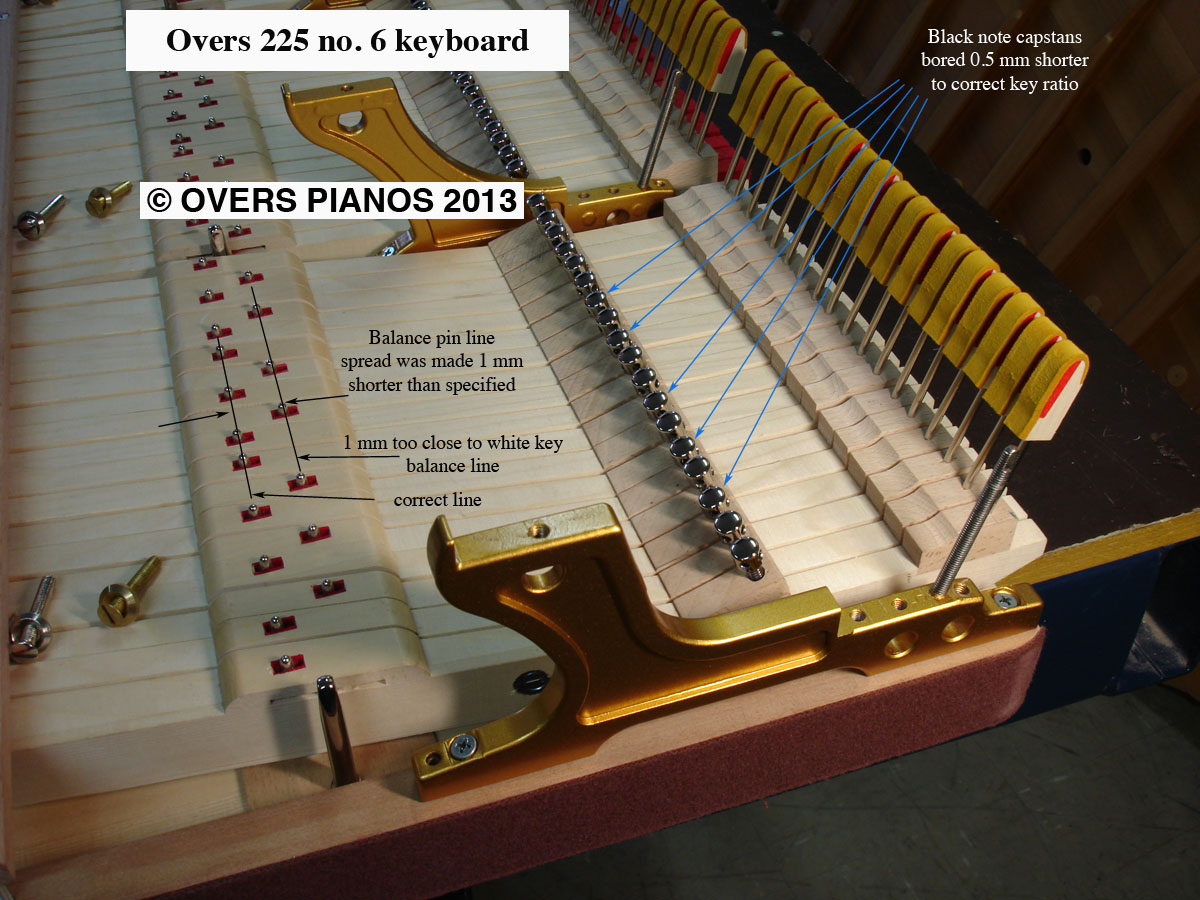
Joseph Garrett
Looks absolutely gorgeous to me.<G> Both of them. To Die For.
Best Regards,
Joe
> [Original Message]
> From: Ron Overs <r...@overspianos.com.au>
> To: <pian...@googlegroups.com>
> Date: 4/8/2013 11:34:37 AM
> Subject: [ptech] Tenor br conversion of hockey-stick 7' grand
Isaac OLEG
This goes back to thread I participated in Someone Elses' PTG.org
regarding what DAndersen calls "pocking" the jack. Pocking means
adjusting the jack by sound and feel, rather than by only visually
aligning the distal side of the jack and knuckle cores @ rest. In
performing this adjustment the jack usually ends up being very slightly
advanced from the static alignment of distal core/jack planes. On static
viewing it seems like this slightly advanced position should be an
inefficient location for the jack @ rest. But jacks don't cheat in this
slightly advanced position. I maintain that the slight reverse initial
movement of the jack actually, achieves the more efficient theoretical
position in actual play.
Jim Ialeggio