Sensor problem
55 views
Skip to first unread message

Kato Kazuo
Oct 27, 2015, 9:57:28 PM10/27/15
to pgFocus
Dear Karl.
I have checked linear light sensor.
On the left side of the sensor light image, there is a narrow peak (indicated by a blue circle. Fig 1). This case, only room light is applied to the sensor.
In the case, when the sensor is positioned in the dark room, the left side narrow peak still exists. I think when the sensor is located in a dark room, left side peak should disappear.
This narrow peak is detected when sensors are on light room, or dark doom.
Sensor broken?
Please advise.
Kazuo Katoh
NTUT
Kato Kazuo
Oct 28, 2015, 2:52:06 AM10/28/15
to pgFocus
As far as I checked, the sensor was supplied for 5V exactly.
Thank you.
Kazuo Katoh
NTUT

Karl Bellve
Oct 28, 2015, 8:50:59 AM10/28/15
to Kato Kazuo, pgFocus
On Tue, Oct 27, 2015 at 9:57 PM Kato Kazuo <kazk...@gmail.com> wrote:
Dear Karl.I have checked linear light sensor.On the left side of the sensor light image, there is a narrow peak (indicated by a blue circle. Fig 1). This case, only room light is applied to the sensor.In the case, when the sensor is positioned in the dark room, the left side narrow peak still exists. I think when the sensor is located in a dark room, left side peak should disappear.
The lowest light levels appear still to be high in your dark room picture. The only way I have found to get down to very low levels (<30 counts), is to put the sensor in a black box, or bag, and also turn the room lights out. The sensor is extremely sensitive. Try and get your background counts lower, and let's see if that side peak disappears.
But, that peak could still be a light leak/reflection or something odd happening to the sensor itself due to light saturation. The light sensor is a made up of a lot of analog transistors, and they react in funny ways when you overdrive them.
It is not a deal killer to have a single pixel be high, especially one on the edge. I could just modify the firmware to not to look for peaks at the edges or you could get a new sensor, but let's check everything first. Also, I would rather you continue to set everything up with the current sensor and then when you are done, get a new sensor.
I checked your first picture you sent, and the light profile did not have that side peak.
This narrow peak is detected when sensors are on light room, or dark doom.Sensor broken?Please advise.Kazuo KatohNTUT
Cheers
Karl Bellvé
Biomedical Imaging Group
Molecular Medicine
University of Massachusetts Medical School
Karl Bellve
Oct 28, 2015, 8:55:06 AM10/28/15
to Kato Kazuo, pgFocus
Kato,
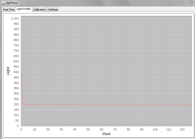
Attached is a light profile that I captured earlier. Notice how low the background pixels are. Try and get yours just as low and see if there still is a side peak.

Kato Kazuo
Oct 29, 2015, 4:01:31 AM10/29/15
to pgFocus, kazk...@gmail.com
Dear Karl.
Thank you so much for your kind information.
I have moved sensor into the dark room.
I will keep sensor next week and check it again.
I will let you know the result next week.
Thank you.
Kazuo Katoh
NTUT
2015年10月28日水曜日 21時55分06秒 UTC+9 Karl Bellve:
Message has been deleted

Ken Jiiii
Nov 4, 2015, 7:53:55 AM11/4/15
to pgFocus
I just connected pgFocus and added the plugin in uManager (just standard settings). After opening the plugin and clicking on light profile I saw the same as Kato. (see file)
The tape is still on my focus and I have not tried anything else yet. I just wanted to let you know that I see the same.
Kind regards
Ken Jiiii
Nov 4, 2015, 10:20:35 AM11/4/15
to pgFocus
By the way, for me there is no change if i put it in a box or have lights on or off (as I said the tape is still on the sensor).
When plugging in pgFocus first the green LED close to the fron of the PCB lights up and after a few seconds the red LED at the back. What do they indicate? I assume the first just the USB connection.
When plugging in pgFocus first the green LED close to the fron of the PCB lights up and after a few seconds the red LED at the back. What do they indicate? I assume the first just the USB connection.

Kyle Douglass
Nov 5, 2015, 3:04:05 AM11/5/15
to pgFocus
Hi all,
I too have always seen this bump on the sensor readout, though it has never negatively affected the pgFocus performance. Once the sensor is illuminated, the light signal is way more than the magnitude of this bump on my system. My guess is there is some extra capacitance at the point of the readout from the pixel array, which creates an excess of charge at this pixel, but it is only a guess.
I do not have an example picture with me now, but I can make the following observations about the bump:
1) Mine is always much smaller in magnitude than what Ken showed above; it is typically about 50 or 100 ADU's above the noise, not ~300.
2) Any background from the wings of the laser typically hides the bump when locked
3) The bump is there for many combinations of exposure times (I have not rigorously tested this, only an observation)
Overall, I have not had any problems with the bump on my system, nor do I think it necessarily indicates a faulty sensor.
On Wednesday, November 4, 2015 at 4:20:35 PM UTC+1, Ken Jiiii wrote:
By the way, for me there is no change if i put it in a box or have lights on or off (as I said the tape is still on the sensor).
When plugging in pgFocus first the green LED close to the fron of the PCB lights up and after a few seconds the red LED at the back. What do they indicate? I assume the first just the USB connection.
I think (and maybe Karl can confirm) that red indicates no IR signal on the sensor, green indicates an IR signal, and blue indicates that the pgFocus is successfully locked onto a beam profile.
Cheers,
Kyle
Ken Jiiii
Nov 5, 2015, 9:14:14 AM11/5/15
to pgFocus
Thanks for the information Kyle. Unfortunately I cannot test it further right now but I will soon.
Maybe Katocan report on a progress regarding that problem soon.
Maybe Katocan report on a progress regarding that problem soon.
Karl Bellve
Nov 5, 2015, 11:30:50 AM11/5/15
to Ken Jiiii, pgFocus
On Thu, Nov 5, 2015 at 9:14 AM Ken Jiiii <jiiii...@gmail.com> wrote:
Thanks for the information Kyle. Unfortunately I cannot test it further right now but I will soon.
Maybe Katocan report on a progress regarding that problem soon.
Kato has shipped his pgFocus back to me so I can take a look at it.
Kato Kazuo
Nov 5, 2015, 10:53:14 PM11/5/15
to pgFocus, jiiii...@gmail.com
Yes. I have already sent pgfocus to.
I have forgotten how I installed the pgfocus software. However, it is apparent that at first I have installed pgfocus under Micro-manager software. Then, I have installed standalone pgfocus software.
I do not know two software conflict image of laser array. Next day, I can not see the peak of laser light.
Katochan
NTUT
Karl Bellve
Nov 6, 2015, 10:56:36 AM11/6/15
to Kato Kazuo, pgFocus, jiiii...@gmail.com
On Thu, Nov 5, 2015 at 10:53 PM Kato Kazuo <kazk...@gmail.com> wrote:
Yes. I have already sent pgfocus to.I have forgotten how I installed the pgfocus software. However, it is apparent that at first I have installed pgfocus under Micro-manager software. Then, I have installed standalone pgfocus software.I do not know two software conflict image of laser array. Next day, I can not see the peak of laser light.
You can use either µManager (/w pgFocus Device Adapter + plugin) or the standalone pgFocus application. You can have both installed at the same time. You just can't run both at the same time.
Karl Bellve
Nov 9, 2015, 2:50:40 PM11/9/15
to Kato Kazuo, pgFocus, jiiii...@gmail.com
The problem with Kato's sensor appears to be a broken solder joint. I am not sure which one broke, but I reflowed all of them and that brought the sensor back to life. Be careful with flexing the pcb that the sensor is mounted on.
So, if you are getting a side peak, I would have someone reflow the solder joints, with plenty of solder flux. Remember, the solder has to seep underneath the chip.
Attached is a capture of his sensor after reflow without light.

Ken Jiiii
Nov 10, 2015, 9:16:57 AM11/10/15
to Karl Bellve, Kato Kazuo, pgFocus
Thanks Carl for the information. Unfortunately I am out of office for 3 weeks. Afterwards I will immediately check the dolder points.
Kind regards
> On 10 Nov 2015, at 02:50, Karl Bellve <karl....@gmail.com> wrote:
>
>
Kind regards
> On 10 Nov 2015, at 02:50, Karl Bellve <karl....@gmail.com> wrote:
>
>
Kato Kazuo
Nov 26, 2015, 10:13:08 PM11/26/15
to pgFocus
Dear Karl.
I have received and checked pgfocus. I have calibrated it. It worked fine. Focus stabilized exactly.
I want to try long term acquire of images using pgfocus.
Thank you for your kind treatment.
Kazuo Katoh
NTUT
On Wednesday, October 28, 2015 at 10:57:28 AM UTC+9, Kato Kazuo wrote:
Kato Kazuo
Dec 3, 2015, 2:07:03 AM12/3/15
to pgFocus
I attached linear light array intensity and stabilized focus image.
CCD camera image is a marker pen containing fluorescent. TIRFM image.
Thank very much for your kind advice.
I also thank mailing list members.
Thank you again.
Kazuo Katoh
NTUT
On Wednesday, October 28, 2015 at 10:57:28 AM UTC+9, Kato Kazuo wrote:
Karl Bellve
Dec 3, 2015, 9:22:01 AM12/3/15
to Kato Kazuo, pgFocus
Hi Kato,
From looking at the first image, looks like you perturbed focus in someway and pgFocus brought it back under control in about 5 seconds.
Looks good.
Good luck with your research!
Cheers
Karl Bellvé
Biomedical Imaging Group
Karl Bellvé
Biomedical Imaging Group
Molecular Medicine
University of Massachusetts Medical School
--
You received this message because you are subscribed to the Google Groups "pgFocus" group.
To unsubscribe from this group and stop receiving emails from it, send an email to pgfocus+u...@googlegroups.com.
To post to this group, send email to pgf...@googlegroups.com.
To view this discussion on the web visit https://groups.google.com/d/msgid/pgfocus/f5fd7b26-d89e-47e0-b69d-fce607998049%40googlegroups.com.
For more options, visit https://groups.google.com/d/optout.
Reply all
Reply to author
Forward
0 new messages