My final Geometry

dalfa...@ut.ac.ir
Hi everyone
First I made my geometry as computational grid as a rectangle box, then an indicator file (based orthogonal grid (og)), included 15 layers (from the bottom aquifer: 51,50,40,30,2 (here 2 meters layer is top of aquifer (Aquifer thickness is 173 meters)),50,50,50,50,50,100,50,500,250,473 (473 meters layer is top of domain based on og, it means highest elevation based on dem is 1623 meters (50+50+50+50+50+100+50+500+250+473=1623) higher than 173 (Aquifer thickness) if I changed the bottom of aquifer’s elevation to 0 (for instance my lowest aquifer elevation is 367 meters of sea level and I decrease all bedrock elevations by 367). After more focus, because I want to use TFG, then I changed my indicator file and ignore 10 up layers and my indicator is as a 3D matrix 60*70*5 (instead 60*70*15) just based on aquifer thickness (51+50+40+30+2=173), and because it follow the terrain its ok and all surface elevations based on my dem as 5 layers included 2 meters top layer to 51 meters bottom layer. To sum up I define my geometry as a computational grid as box (including a rectangle box 60*70*1796(1623+173) and an indicator file as aforementioned with thickness of 173 meters.
I done it by dz scale as follow commands:
pfset ComputationalGrid.NZ 18
pfset ComputationalGrid.DZ 100.0
pfset Geom.domain.Upper.Z 1800.0
pfset Solver.Nonlinear.VariableDz True
pfset dzScale.GeomNames domain
pfset dzScale.Type nzList
pfset dzScale.nzListNumber 5
# 5 layers, starts at 0 for the bottom to 5 at the top
# layers are 2 m, 30 m, 40 m, 50 m, 51 m
#aquifer thickness is 173 m
pfset Cell.0.dzScale.Value 0.51
pfset Cell.1.dzScale.Value 0.5
pfset Cell.2.dzScale.Value 0.4
pfset Cell.3.dzScale.Value 0.3
pfset Cell.4.dzScale.Value 0.02
I want to be sure if all I done is correct or maybe have some mistakes. Or my geometry input is correct?
Best
Sadegh Dalfardi
dalfa...@ut.ac.ir
22 Tir 1401 4:36 PM, dalfa...@ut.ac.ir wrote:
Hi
I ask a question but didn't get answer, maybe it wasn't obvious, I noticed in some examples like Little washita indicator is linked and adjust with computational grid (Z upper in indicator and computational grid are conform, but in other item, I have read that z-upper is synched to computational grid, and is not linked with the Z multipliers (for instance nz is 5, dz is 100 and z-upper is 500 like computational grid but dzscale is used and all thickness is 102 meters that is not synched with computational grid and box geometry). I used a box geometry and an indicator with 5 layers based on aquifer thickness (173 meters), it means any surface elevation cell (no matter how much the cell elevation is) defined to 173 meters under surface as 5 layers. Now I wonder how relate different z layer in two geometry (box and indicator), for instance my indicator is included 5 layers with different dz (using dzscale, 51,50,40,30,2),but my box geometry and also computational grid should be defined spanning highest elevation to lowest elevation (for instance highest 2163 and lowest 367 (sea level elevation of lowest part of aquifer)), it means my z-lower is 367 and z-upper is 2163 and dz*nz must be 1796. I am confused how to define my box and computational grid dz and nz that match the indicator. maybe what I understand about tfg and indicator is wrong? I hope i explain my points of view correctly. any tip or guide will highly appreciated.
Best
Sadegh Dalfardi
--
You received this message because you are subscribed to the Google Groups "ParFlow" group.
To unsubscribe from this group and stop receiving emails from it, send an email to parflow+u...@googlegroups.com.
To view this discussion on the web visit https://groups.google.com/d/msgid/parflow/e76cc11a63898254c9d01fb905079d7f%40ut.ac.ir.
For more options, visit https://groups.google.com/d/optout.

alanl...@gmail.com
dalfa...@ut.ac.ir
Hi Alan
Thank you for kind answering, my domain box is like this:
Lower x 0.0 - lower y 0.0 - lower z 0.0
upper x 60000.0 - upper y 70000.0- upper z 2154.0 (2521-367) (2521:highest cell elevation and 367 is sea level elevation of lowest part in aquifer(most bottom aquifer part)
(dx=1000.0 dy=1000 dz=? , nx=60 ny=70,nz=?)
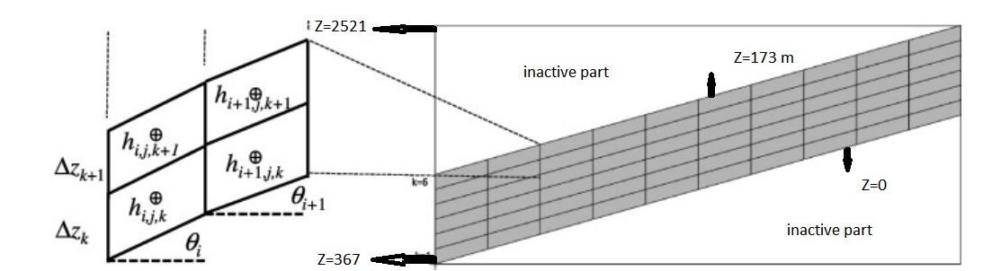
Aquifer thickness is not same in all sections, it changes between 2 meters in some mountainous sections up to 173 meters in most thickness section in plain part. Then i can’t use just box as geom input otherwise box need to have one geometry but i have about 25 different kind geometries (about 8 geometries are important in case of surface and ground water interaction and other geometries are different kind of ingenious rocks that have no effect on interaction, I define them because I thought I should do as if they are in regions). then i decided to make an indicator fields that supports my 25 geometries. Because of not being flat i want to use tfg network. in other side based on my geometries and aquifer thickness, I divided my domain in 5 layers from the surface to bottom included 2, 30, 40, 50, 51(Because the layers follow the slope, so they become steep, that is, for example, the cell with a height of 2521 layers is 2 meters from 2521 to 2519, and the cell with a height of 540 layers is 2 meters from 540 to 538 meters, based on what i understand its true in the case of using TFG network and orthogonal network means, for example, if the 2-meter layer is selected based on the 540-meter cell, it will be from 540 to 538, and the cell with a height of 2521 does not fall in this 2-meter layer and the layers do not follow the slope.) Now my question is because my layers have different thickness i used dzmultiplayer and need to define dz and nz the same as what is defined for domain box and also the indicator must match exactly all domain or computational grid and based on my domain and computational grid nz*dz must be 2154 while my nz*dz based on my aquifer thickness is 173 meters in this situation what should i do to prepare my geometry? One things that come to my mind is that because just 173 meters (aquifer thickness) is important for modeling and also by using tfg all cells are included no matter how high cell's elevations are. But in this way nz*dz equals 173 (even if all cells were included because of the same slope of different layers) and it will produced a box with the same dimension as domain box and inactive sections in up and down of layers that we don’t define but i don’t know if it is correct? Or model discern that inactive parts? I tried to show it exactly based on Maxwell 2013 TFG.
Another question came to me after your answer is that because i want to couple with clm and based on manual they act on 10 top layers in common, but i have 5 layers. Wont it faced problem? Or maybe it’s better to divide the 2 top layers (2 and 30) in more layers that are thinner? But if I do so the layers located internal to layer 2 or layer 30 have the same geometry.
Best
Sadegh
To view this discussion on the web visit https://groups.google.com/d/msgid/parflow/3829569a-e539-4531-9c42-9cc325348501n%40googlegroups.com.
alanl...@gmail.com
dalfa...@ut.ac.ir
Hi Alan
Thank you so much for shedding light on this tippy subjects, I really appreciate your helps. yes as you said based of my aquifer thickness (173 meters) and also based on different between highest and lowest elevation (2521,521), I chose my thickness domain 2000 meters and of 19 layers. I made an indicator geometry input and in this indicator all cells with 0 code are located outside of my domain. And also a solid file with one solid (domain) and no user specified patches and order of patches are bottom top left right front back. Now I think I don’t need box and I used the indicator and solid file for defining geometry. (Outside domain cells indicated by indicator and all subsurface heterogeneities have been indicated in the indicator file, by using solid file also inactive cells inside domain along with Z axis will be discerned. I visualized indicator and vtk file in paraView and indicator is correct and also solid file sounds correct too. Is there other way to be sure about solid file correction?
Best
Sadegh
To view this discussion on the web visit https://groups.google.com/d/msgid/parflow/b613940a-998f-417d-a1c3-048cb061a8ecn%40googlegroups.com.
alanl...@gmail.com
dalfa...@ut.ac.ir
I have 2 option for selecting my domain thickness:
1-Based on 3 values (2521 as highest elevation located in active domain, 519 as lowest elevation located in active domain and 367 as lowest elevation of aquifer) i chose thickness=2154 (2521-367)
2- just based aquifer thickness that is 173 meters and using TFG i chose thickness=173
But as you said calculations are performed on an OG grid then I think I used the first option and select 2154 as domain thickness.
Is it ok or i should consider other factors and i haven't understand yet?
I have another question:
For instance if i want to define my domain boundaries as no flow boundary conditions except top boundary, then for making solid for all domain by pfpatchysolid i just need a mask with 1 as active and 0 for inactive cells or i need to prepare enhanced mask and define left, right, front and back as positive number (for instance 2,3,4,5) and use it for making solid?
Best
Sadegh
To view this discussion on the web visit https://groups.google.com/d/msgid/parflow/9a0ccb91-2c32-4607-9f4f-a66cf168e706n%40googlegroups.com.