How to create properly orbits around on earth with osgEarth?

John Blue
Hi to all,
It is my first time that I program graphics for simulation. I am an omnet++ user and I need to use graphics for my simulation. I think is the most relevant group hear for this question. I try to do some simulations with satellite communications. One aspect of the simulation is the orbits of the satellites. Omnet++ has a sample with satellites and uses the osg (https://github.com/omnetpp/omnetpp/tree/master/samples/osg-satellites). I use this code for reference to create my code for constellations. I use the orbital elements to calculate the position vector and the velocity vector. I use this book for references to the algorithms for the calculation of the vectors more specific the algorithm 4.2. For the parameters of the constellation, I use a code that deviates a circle with orbital planes for the angle-distance of the planes and a circle with the number of satellites for the angle-distance of satellites in the orbital plane.
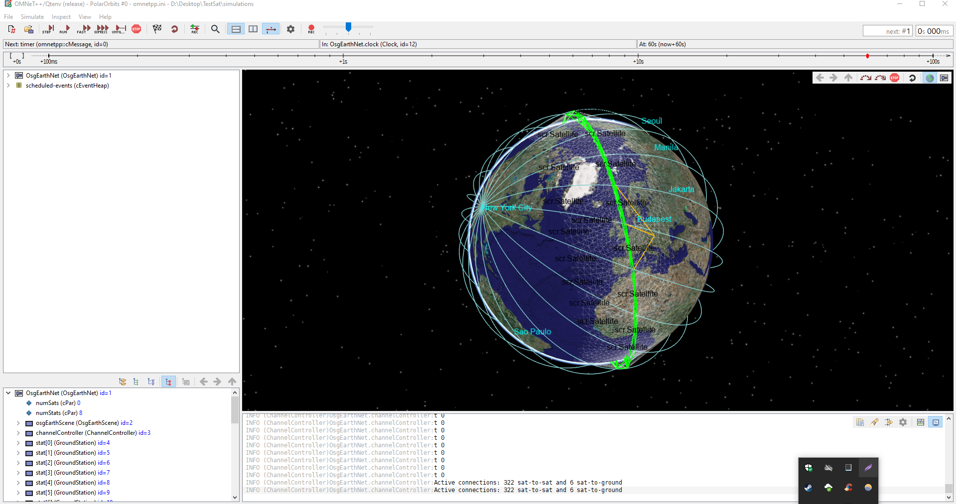
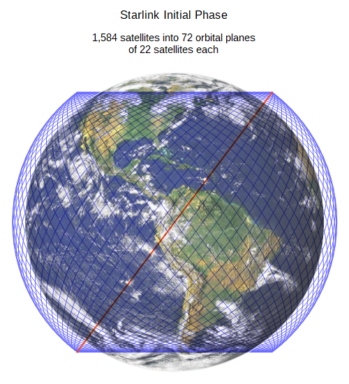
My problem is that I can't create properly orbitals planes for the constellation. For example, I want to create a Starlink constellation from the pitcher down we see how the orbital planes are placed. In my screenshot, you can see my falt in placement.
I believe my falt is in the variables orbitX and orbitY. Can someone help me to fix this issue? I am a total beginner in osg. I attached my code below.
Thank you for your time.
P.S.
I apriceite any help or sugestion.
Some reference for orbital elements in the doc2 file
Ioannis Aggelis

Ravi Mathur
--
You received this message because you are subscribed to the Google Groups "OpenSceneGraph Users" group.
To unsubscribe from this group and stop receiving emails from it, send an email to osg-users+...@googlegroups.com.
To view this discussion on the web visit https://groups.google.com/d/msgid/osg-users/9998a7eb-7e13-4369-b109-bd8c71d946f6n%40googlegroups.com.
John Blue
Dear Ravi,
Thank you very much for your quick response I appreciated it.
The last two days I was trying to check the correctness of the calculation orbits more specifically the Position and Velocity vectors. I check your suggestion to validate my orbital vectors with this website where it is used orbital elements to do the simulations. As you can see from the next example my calculation is correct.
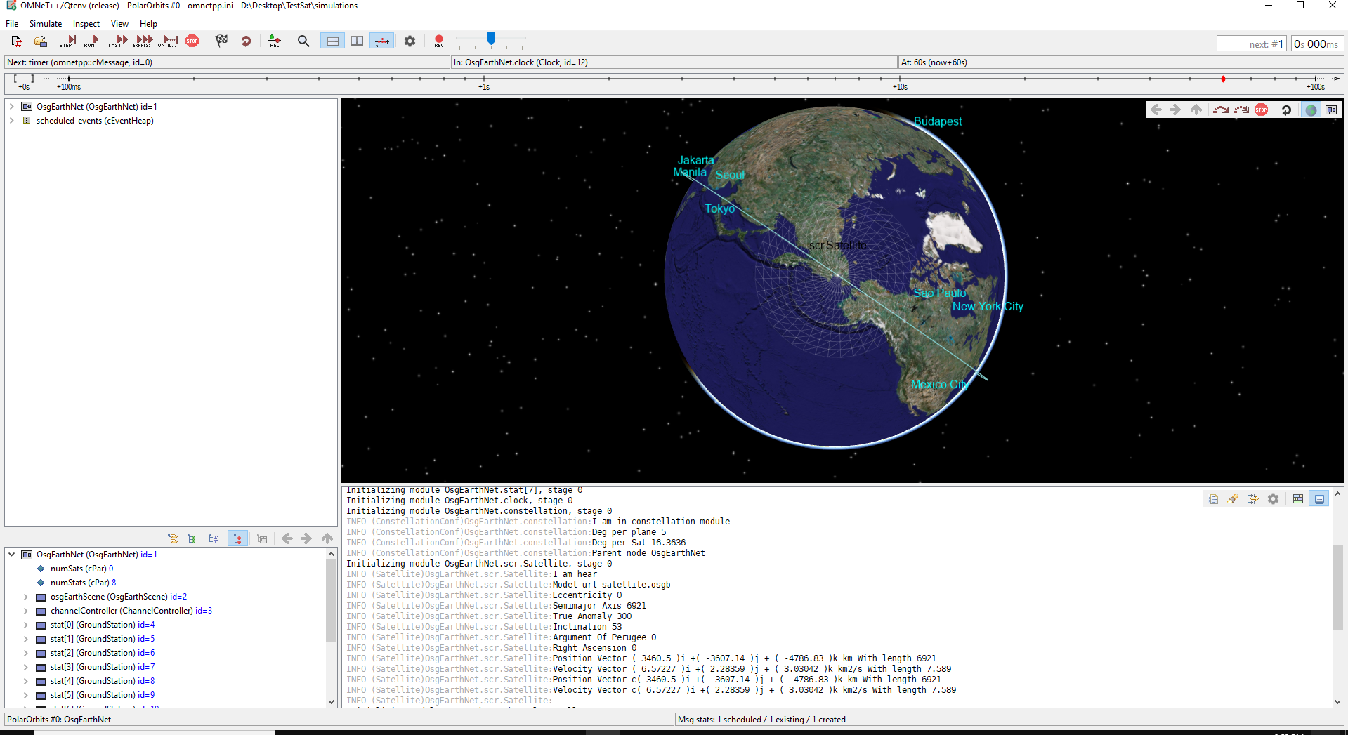
Parameters of example:
Eccentricity = 0deg
Semimajor Axis = 6921km
True annomaly = 300deg
Inclination = 53deg
Right Ascension = 0deg
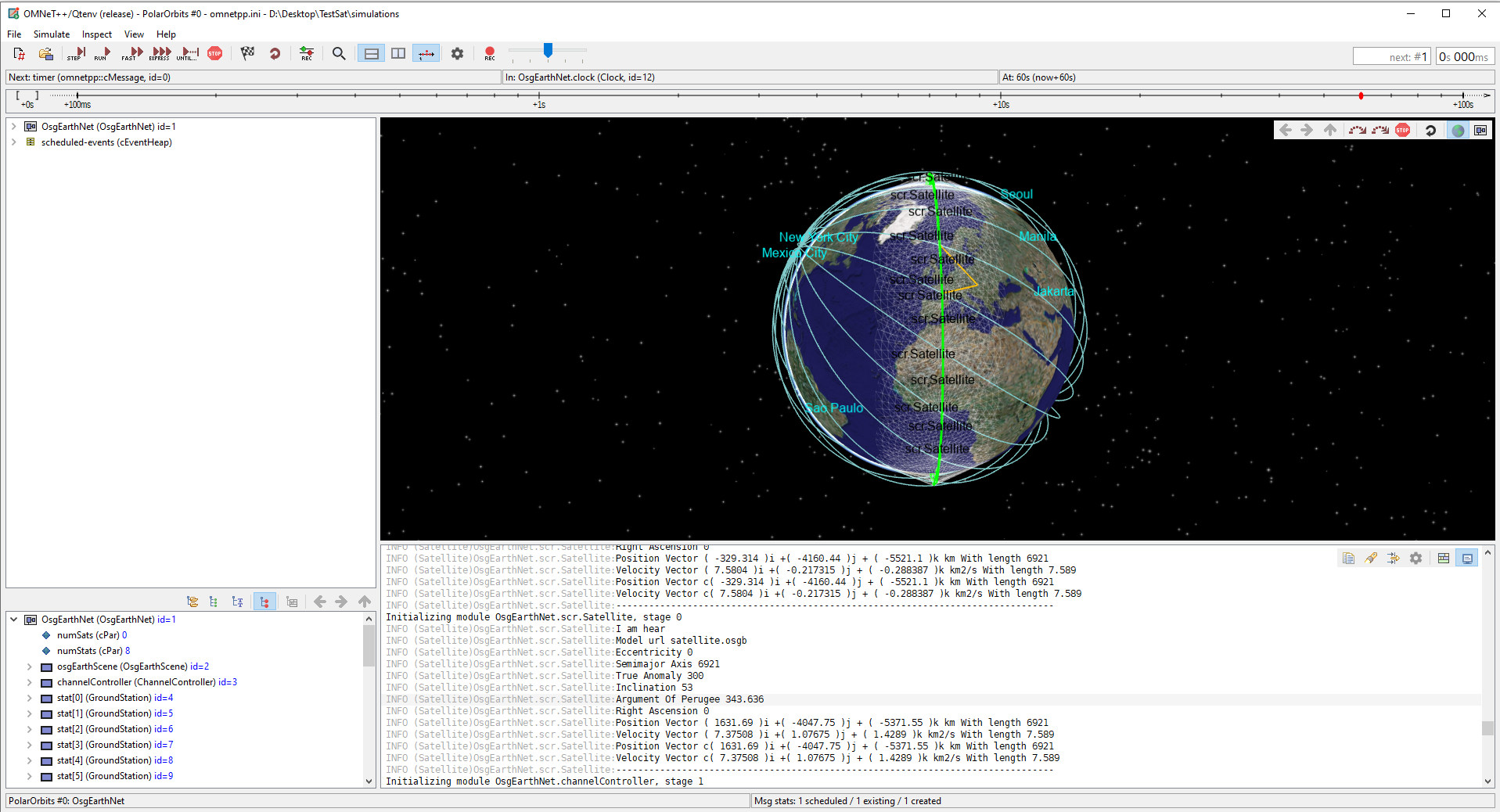
As you can see from the attached photos my position and velocity vectors are corrected. The position of my satellite is closed to Alaska but as you can see from the photo of the online simulator the actual position is some were down to the pacific ocean.
I run a second experiment to check the calculations for a random orbital plane. I use the True anomaly to specify the plane and the Argument Of Perigee to specify the satellite in the orbital plane. Form the second screenshot you can see that all the visually position is wrong. I have attached also a .txt file with my parameters and the calculations of the vector. My calculations for the vectors are corrected as I can see. Also, I have used two different methods to calculate and validated (in the code that I have attached above is the functions 1)getPositionVector, getVelocityVector. 2) calulateTheStateVectorsFromOrbitalElemnts).
In short, I don't know and understand how to use the position and velocity vectors to create the orbits. The code which I use to create my own is from line 75 to 83 and line 221. I don't understand what they do and how to calculate the orbit.
Ιs there a way to use the position and velocity vector to create the orbit and position the satellite correctly or any other suggestion?
Thanks for your time.
Ioannis Aggelis
P.S.
I apologize for the length of this mail, I try 3 weeks now to do it properly, your help is very important. Thank you again.