[ENGINEERING] Stepper motor drives for optical printers

Greg Ercolano
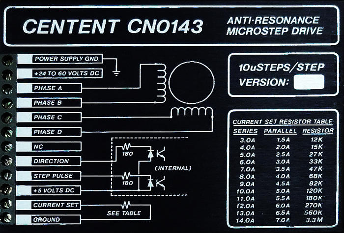
Centent:

Greg Ercolano
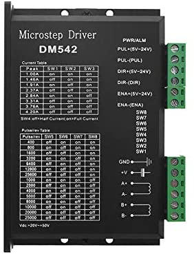
Adding to this thread; a wiring diagram I used for wiring up a test for the Leadshine DM542 drives:

The DB37 connector breakout board is shown wired for being
connected (via a DB37 cable) to any of: Kuper RTMC16, RTMC48,
Kuper Industrial cards,
or the new OPCS A800 stepper cards, which are all compatible with
the OPCS software.
OPCS A800 card (8 channel, ISA slot)
RTMC16, RTMC48 and Kuper "Industrial" cards (16 and 48 channel ISA)


Greg Ercolano
Adding to this thread; a wiring diagram I used for wiring up a test for the Leadshine DM542 drives:

The DB37 connector breakout board is shown wired for being connected (via a DB37 cable) to any of: Kuper RTMC16, RTMC48, Kuper Industrial cards,
or the new OPCS A800 stepper cards, which are all compatible with the OPCS software.
I should add the breakout board at the top right is a $12 off
the shelf board I purchased from eBay, e.g.
https://www.ebay.com/itm/DB37-M2-Female-D-SUB-37Pin-Plug-Breakout-Terminal-Solderless-Connector-Outward/183533637861
I bought 5 of them, as they come in handy for debugging as well as actual motor installations.

They are all of good quality and have mounting holes so they can be screwed down. There's also
insulating rubber on the bottom to prevent shorts, but I'd advise standoffs anyway to keep the board
from touching the surface it's mounted to.
---
The pandemic has allowed me to have time to design specialized circuit boards for this type of thing, so I finally
got around to making a board that fans out the DB-37 to RJ-45 connectors, one per motor channel, so that one
can simply cut up a bunch of old cat5 cables to distribute the computer's step/direction signals out to the drives
as individual wires, with pullup resistors built into the board to prevent crosstalk/noise.
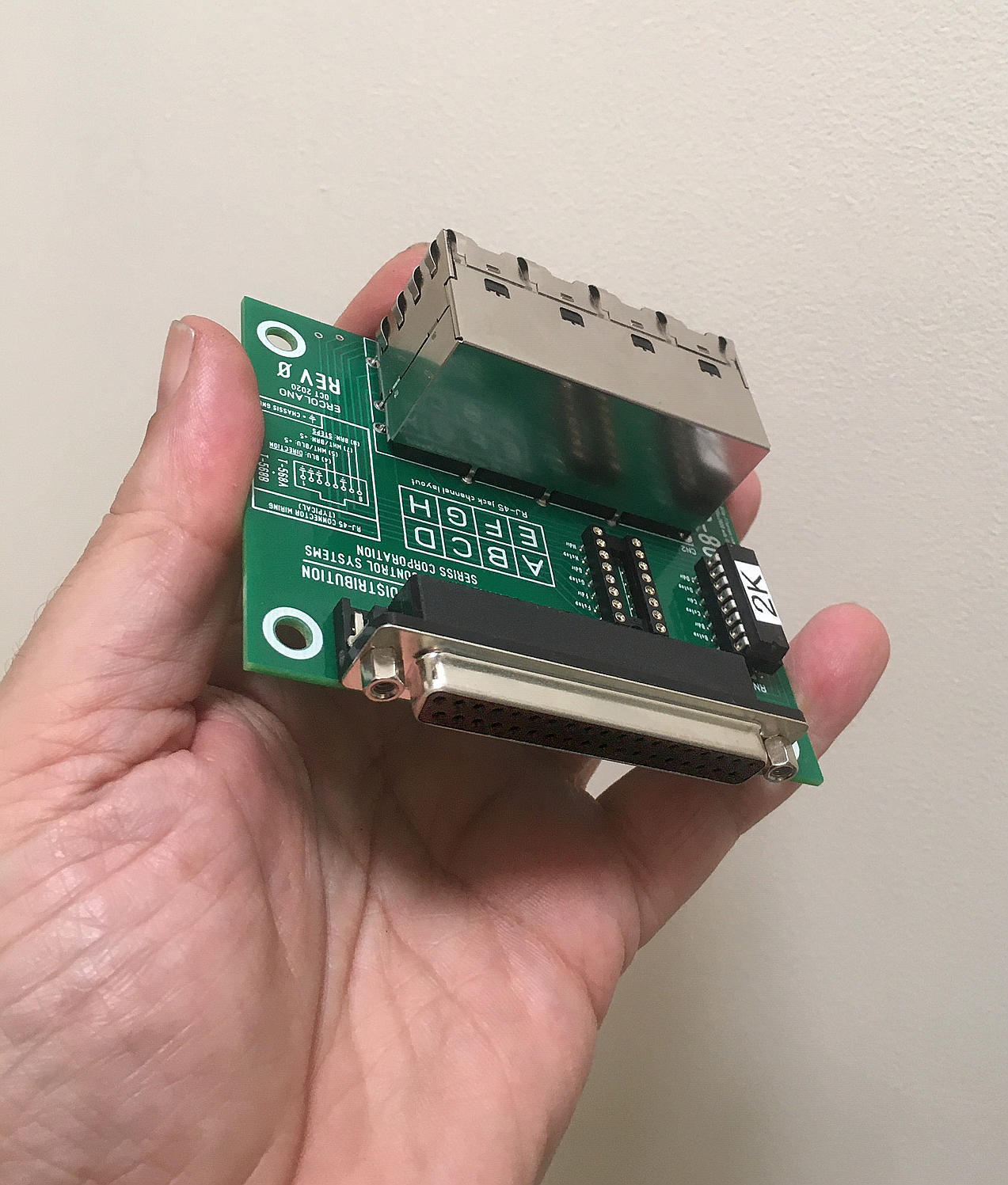
Just received some boards back from the printer today, and
soldered it up; looks like this:
 There's a female DB-37 on the top of the board that would be cabled to the Kuper or A800 stepper card in the computer, and a block of 8 RJ-45 connectors on the bottom which would fan out the steps/direction signals to the stepper drive units, one cable per channel. The board has four mounting screw holes to allow the board to be mounted to some available space inside the optical printer using 1/8" machine screws/nuts with either metal, rubber, or nylon standoffs. |
 Here's the bottom of the board showing the 8 RJ-45 connectors. Regular cat5 or cat5e patch cables can be cut in half and used to fan out from this block to the terminal blocks on the stepper cards. Each RJ-45 connector has one twisted pair for the steps signal (+5V and steps), and a separate twisted pair for the direction signal (+5V and direction), so that each pair can be wired to the terminal screws on the Gecko, Centent, or Leadshine DM542 drives. |
 Here's the female DB-37 connector, which can be connected to the computer's DB-37 connector (on the back of the Kuper card or OPCS A800 card) using a cable with male DB-37's at either end. |
 Here's the board patching the "A" output from the RJ-45 connector to the "A" channel motor drive using a clipped cat5 cable. The steps and direction signals are very low frequency compared to ethernet, so any of cat5, cat5e, cat6, etc. cabling will work. Often people have a lot of old cat5 cable lying around, a perfect use for it..! |
Greg Ercolano
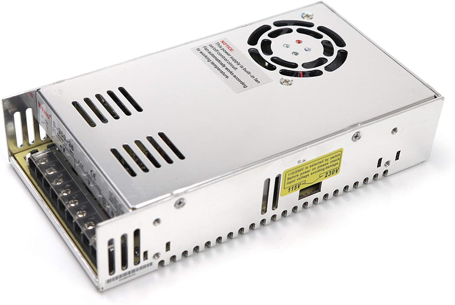
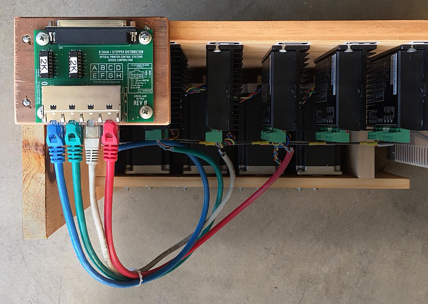
Here's a top view of my bench test stepper drive setup showing the SD-800 mounted with 4 patch cables wired to the drive terminal blocks:
For industrial interface boards like this, I try to always include wiring diagram info on the board's silk screen, in this case for the patch cable wiring:
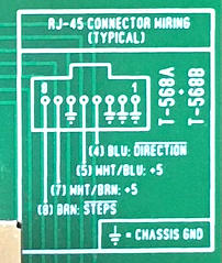
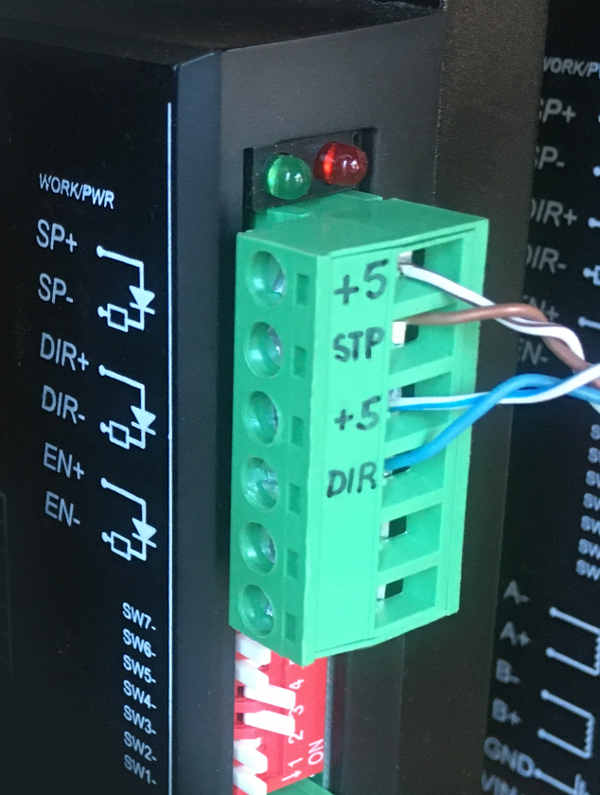
So on the drive terminal blocks, the brown wire pair is for "step pulses", the blue wire pair runs the 'direction'.
Greg Ercolano
Here's a revised stepper drive wiring diagram showing the SD-800
wiring to 4 of the possible 8 stepper drives.
I'll actually be wiring one of these up today for a customer.
Posting it here so I can always find it when onsite..!
Should help those of you wiring up printers yourselves as well, or
if you have an onsite engineer.
Patch cable colors are not critical; what's critical are the wire
colors within the cable; the brown/brown-white pairs for "steps",
the blue/blue-white pair for "direction". The "enable" inputs are
left floating, or can be controlled by the parallel port.

The SD-800 eight channel "Stepper Distribution" board works well -- mounted it to my 4 channel stepper test setup with a DB-37 male/male ribbon cable, and some RJ-45 cat-5e cables trimmed and wired to the drives; everything runs OK, signals are clean.
Here's a top view of my bench test stepper drive setup showing the SD-800 mounted with 4 patch cables wired to the drive terminal blocks:
For industrial interface boards like this, I try to always include wiring diagram info on the board's silk screen, in this case for the patch cable wiring:
So on the drive terminal blocks, the brown wire pair is for "step pulses", the blue wire pair runs the 'direction'.
On the A-800 stepper pulse generator board in the IBM PC, the steps and direction signals are open collector outputs (active ground) relative to +5V. Which means +5V is common to all the signal inputs.The SD-800 distribution board includes the common +5V distributed on the white stripe wire of each wire pair, ensuring wiring is just one wire per terminal screw; no jumper wires or pull ups are needed at the terminal block, e.g:
The solid colored wires go to the negative (-) input, the white wires with the color stripe go to the positive (+) inputs.
Note: When wiring to the screw terminals on the stepper drives, ensure the wire was properly fastened after tightening each screw by giving it a "tug". Some terminals have a "rising plate" when the screw is tightened; and if the wire is inserted /below/ the rising plate, when the screw it tightened the wire won't be captured properly, and will be loose in the hole even after tightening. You have to be extra vigilant when wiring this type of screw terminals.
On Friday, October 16, 2020 at 5:02:03 PM UTC-7 Greg Ercolano wrote:
On 2020-10-10 00:00, Greg Ercolano wrote:
Adding to this thread; a wiring diagram I used for wiring up a test for the Leadshine DM542 drives:
[..]
Greg Ercolano
OPCS is running on the computer at the far right. Lots of axes of motion on this printer.
The camera operators liked having the keyboard and screen mounted up near the camera.

Title House had several OPCS systems, including one big red
multiformat printer that John Monceaux
built for them from scratch that could do imax/vista/35mm.
Greg Ercolano
Here's a revised stepper drive wiring diagram showing the SD-800 wiring to 4 of the possible 8 stepper drives.
I'll actually be wiring one of these up today for a customer. Posting it here so I can always find it when onsite..!
Should help those of you wiring up printers yourselves as well, or if you have an onsite engineer.

..so it's best to braid the wires before adding connectors, resulting in:

I've had 6 and 8 wire motor braiding instructions on the OPCS website for decades,
but now that these 4 wire NEMA 23 motors are coming from Amazon as kits,
I recently added this pattern for braiding the 4 wire motors:

This pattern results in a more "rounded" distribution of the wires, whereas the other 6 and 8 wire braids
I've had all these years on the website yield a more "flat" braid.
I find the flat braid is easier to execute, but if you get the hang of the above, it goes quickly too.
When doing the above 4 wire braid, the trick is to start with the outer wire on the left, and bring it under
the two wires to its right (center pair) and up then back over to the left to become the inner wire of the left pair.
Do the same thing for the right outer wire, and simply repeat, alternating left and right.
You'll notice in the above, the red/green wires always end up staying on the left,
and the yellow/blue wires always end up being on the right.
The two wires in each pair just alternate being the inner or outer wire of the pair on that side.
When you reach the end of the wires, you can knot one pair over the other two and vice versa
to keep the wires from unbraiding while you solder the connectors.
Or, just wrap some tape around them to keep them from unraveling while you solder the
connectors, and then remove the tape when done; once the wires are soldered to the connector,
the braid will not unravel.
Greg Ercolano
This is using the wire braiding technique (below this photo) described in the last post and on the OPCS website:
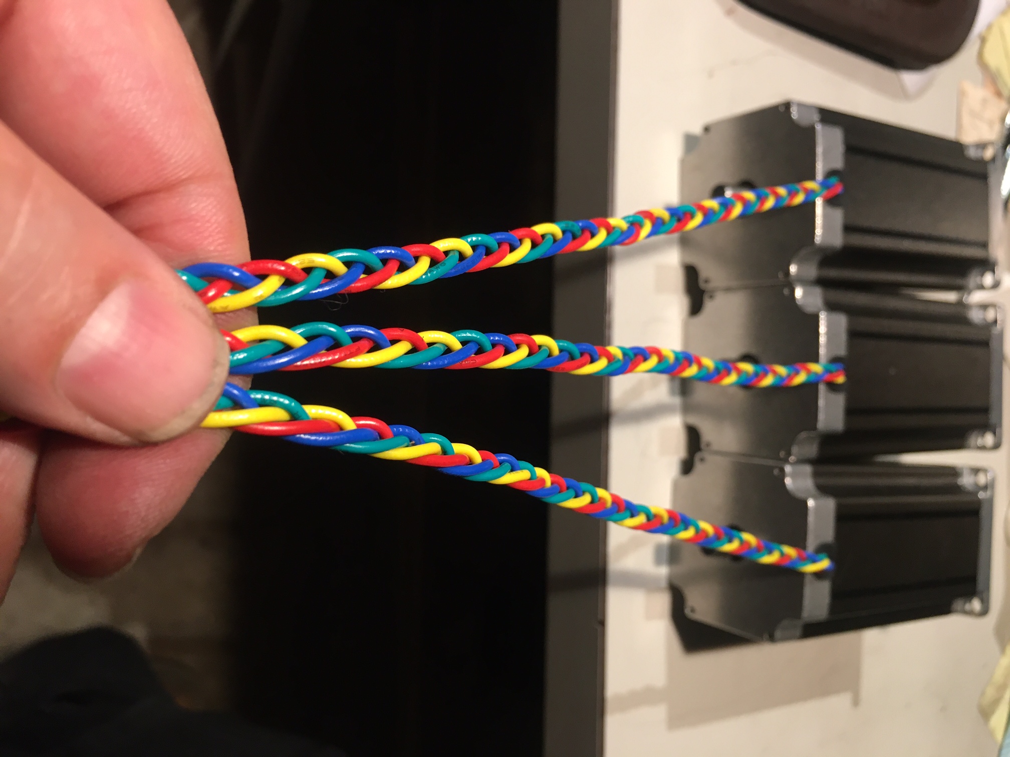
[..] I've had 6 and 8 wire motor braiding instructions on the OPCS website for decades,
but now that these 4 wire NEMA 23 motors are coming from Amazon as kits,
I recently added this pattern for braiding the 4 wire motors:

This pattern results in a more "rounded" distribution of the wires [..]
Greg Ercolano
If you need some examples:
_____________________________________________________________________________________________________
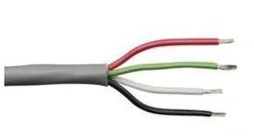
Belden 8489
The above is a very common motor drive cable I've run into a lot in motor control for the film industry.
The gray PVC jacket is 0.032" for the outer diameter (the diameter is important for mating to connectors),
the conductors are unshielded. Mates nicely into XLR connectors and is 18 AWG, good for even large motors.
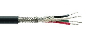
Belden 8424
Labeled as "microphone cable", but great for stepper motor cables.
A black EPDM rubber jacket makes it more flexible. A classy, high quality, smooth looking cable.
Common on high end systems, where looks are important. Since it's mic cable, it's heavily shielded with a tight braided
shield that runs completely around the inner 20 AWG 4 conductors. The slightly thinner gauge conductors helps make the
cable more flexible, giving it a nice droop. Fits perfectly in XLR connectors.
_____________________________________________________________________________________________________
Other 4 conductor cables work fine too. Sometimes you can find 4 conductor AC cable used for power cords
that would work equally well.
Sometimes you can find used 100' lengths of cable from industrial surplus (Apex Electronics in the LA area) or on ebay that can be very cost effective, as usually this cable purchased new is very expensive, several dollars per foot.
Greg Ercolano
[..]
The pandemic has allowed me to have time to design specialized circuit boards for this type of thing, so I finally
got around to making a board that fans out the DB-37 to RJ-45 connectors, one per motor channel, so that one
can simply cut up a bunch of old cat5 cables to distribute the computer's step/direction signals out to the drives
as individual wires, with pullup resistors built into the board to prevent crosstalk/noise.

Update Aug 26 2023:
Recently an OPCS customer requested setting up a 16 axis printer.
I really thought at this late a date, no one would need more than 8 channels on an optical printer, but here we are..!
The OPCS software supports 16 channels (max) with the RTMC16 and RTMC48 boards,
so I recently created a 16 channel version of this distribution board called an SD-1600.
This can break out the Kuper Controls RTMC16 DB-37 connector into 16 separate RJ45 patch cables, and looks like this:
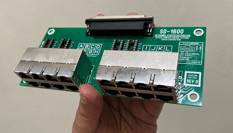
It's basically just a larger version of the SD-800 card.
The webpage for this new SD-1600 board, including schematics and gerber files
will be posted here: https://seriss.com/opcs/sd-1600/