[ENGINEERING] Tension motor solid state relay/variac wiring for optical printer
131 views
Skip to first unread message

Greg Ercolano
Oct 9, 2020, 8:40:01 PM10/9/20
to optical-printing
Also, here's a pic of a printer I wired for PHI (Packhard
Humanities Institute) a few years ago, one of the rare times in the last few years I did the hardware on
printer upgrades.
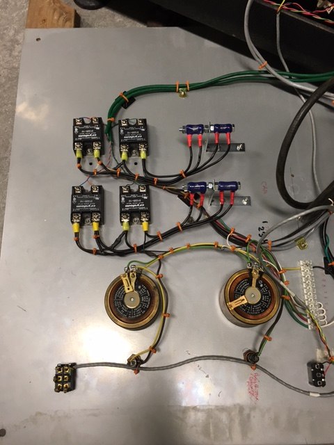
This is the bit of wiring for the variacs to control camera and projector tension motors.
The 4 CRYDOM solid state relays at the top-left are under OPCS software control
to switch the tension power from forward to reverse for cam + projector.
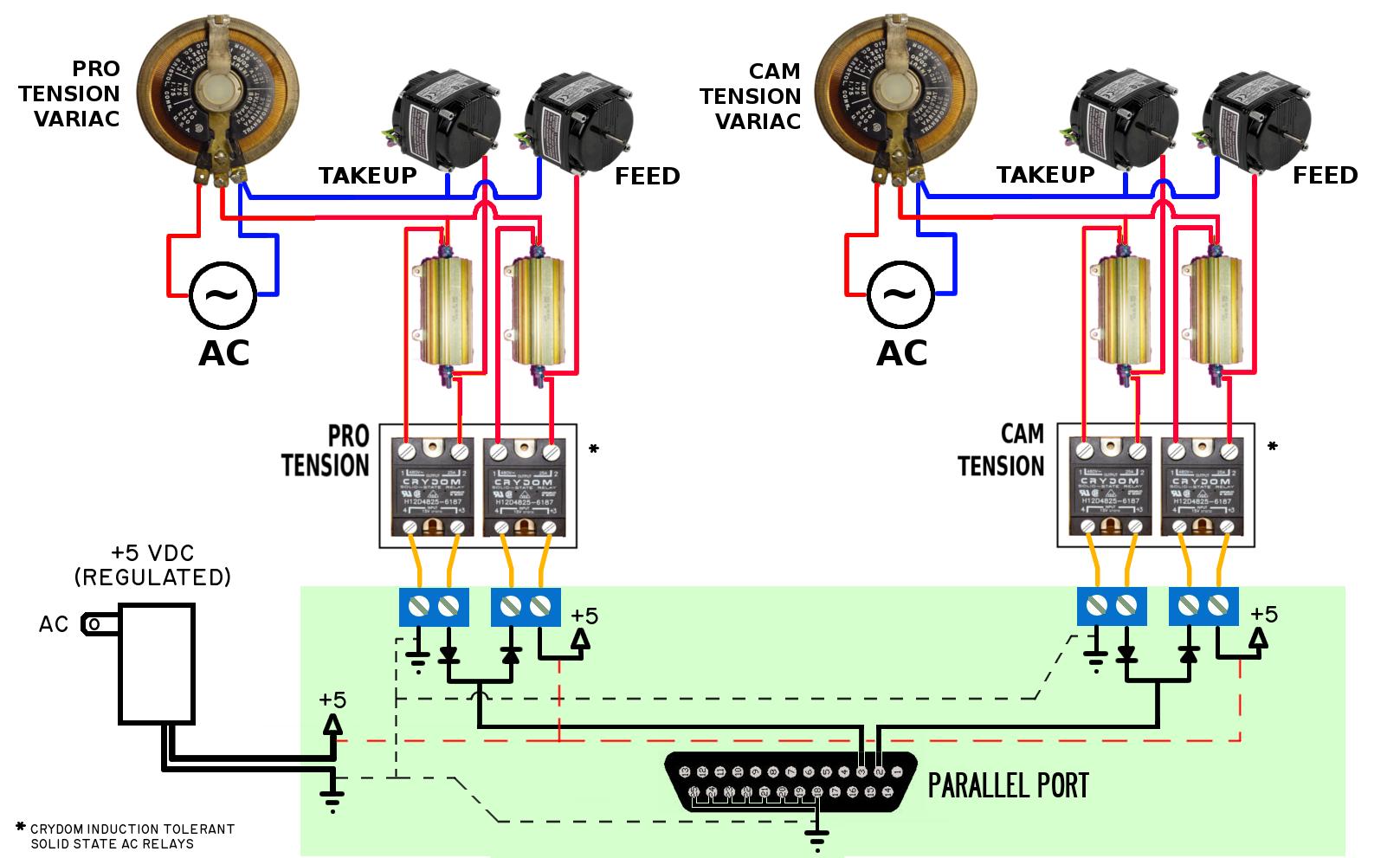
The idea is in "forward" mode, the variac sets the takeup tension set by the variac,
and the 'feed' tension is leakage current through the power resistors at the top right.
When the motor direction is changed to 'reverse', the relays swap this around.
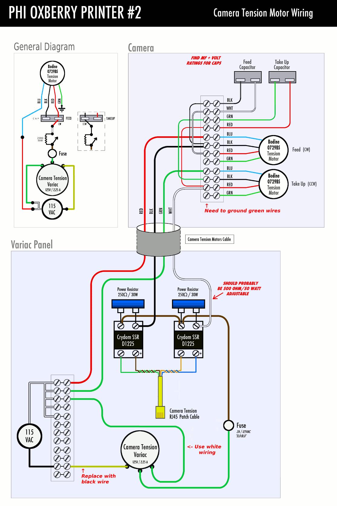
The tension motors keep tension on the film, both camera and projector.
Here's a current link to the product from their website store:
https://www.bodinedirect.com/product.sc?productId=136&categoryId=150
..or the product page:
https://www.bodine-electric.com/products/ac-motors/k-2-series-ac-induction-motor/0712/
They call them "High Slip" motors because they spend most of their time NOT turning, just keeping pressure on the film. The fact these motors can remain "stalled" almost all of the time they're operating is what makes these motors special.
The replacement capacitors can be purchased from them too, which are these
with the screw mounts:
https://www.bodinedirect.com/product.sc?productId=824&categoryId=255
Here's a few wiring diagrams I've provided in the past:
Gmail Ercolano
Jan 29, 2021, 4:54:05 AM1/29/21
to optical-printing
On 10/9/20 5:40 PM, Greg Ercolano wrote:
[..] Here's a few wiring diagrams I've provided in the past:
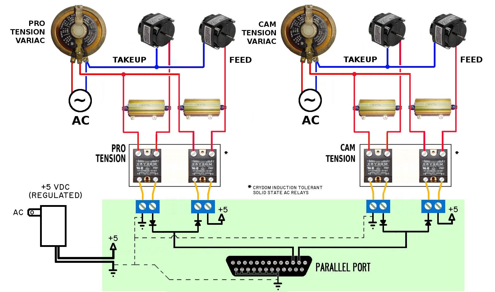
Here's a slightly improved verison of that first diagram,
removing some of the visual complexity
in the wiring between the solid state Crydom relays and the
motors:
Greg Ercolano
Apr 4, 2024, 8:54:32 AM4/4/24
to optical-printing
Here's an updated version of the tension motor wiring showing the PIO-100 board (in place of direct wiring to a parallel port):
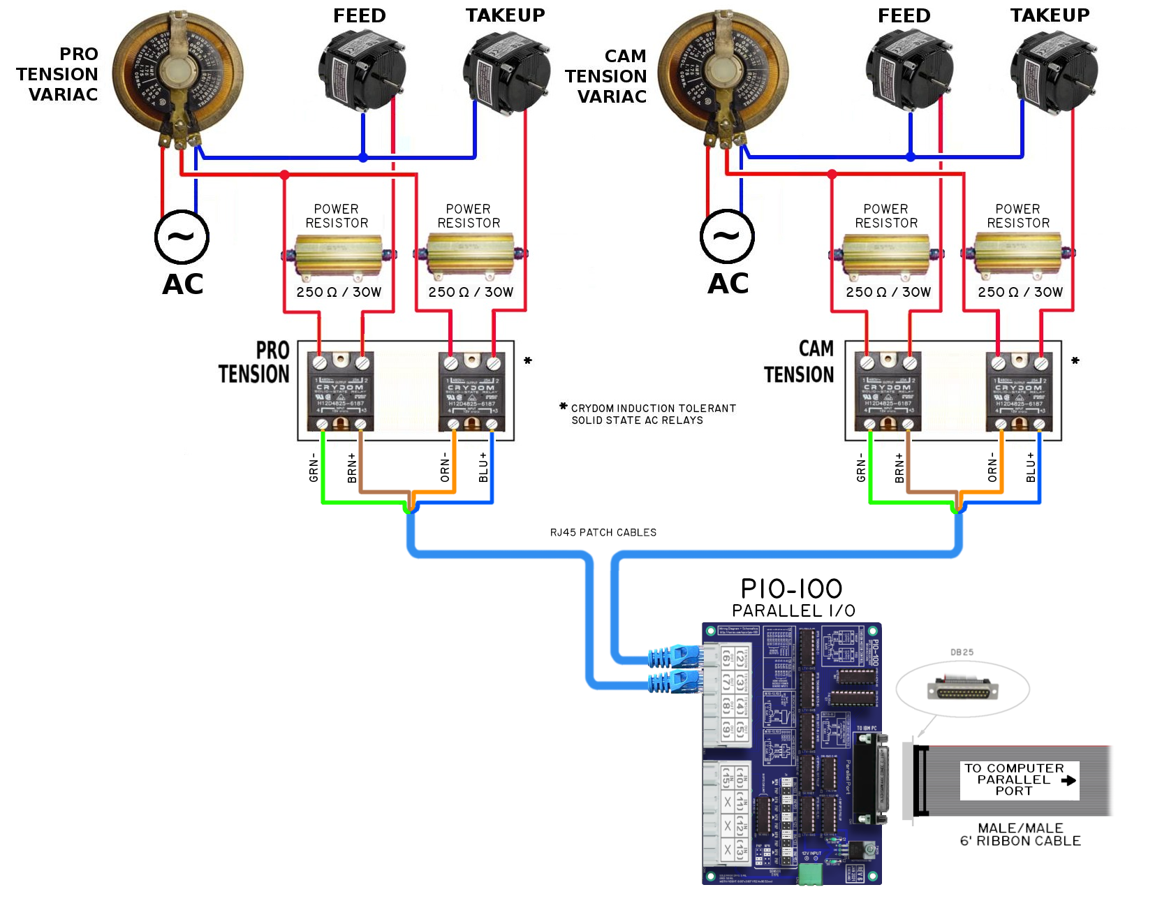
NOTE:
In this diagram, the capacitor associated with each tension motor is not shown for simplicity.
For capacitor wiring, refer to the documentation in the first post in this thread.
For capacitor wiring, refer to the documentation in the first post in this thread.
Reply all
Reply to author
Forward
0 new messages