uploaded a model of a design i have been working on
969 views
Skip to first unread message

Michael Stalls
Jan 18, 2013, 2:56:12 AM1/18/13
to ope...@googlegroups.com
Hi all
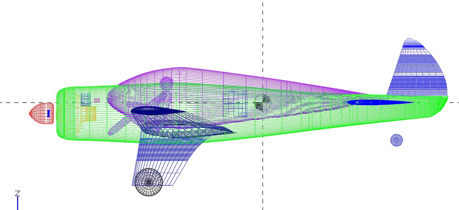
this is my first post although i have playing around with vsp for quite sometime now. i have uploaded a model of a 2 seat sport aerobatic bi plane i have been designing (and plan to build and fly at some point!)
currently i am analyzing the aircraft using textbook methods as i dont have access to vorlax or any other CFD package at the moment. At some point i hope to do some cfd analysis and optimization using openfoam (an open source cfd code), has anyone had experience interfacing VSP with this soft ware? Also is there a good guide to the use of vsp features such as COMPGEOM, CFDmesh, mass properties, aeroref, etc? i would like to make sure i am using the features and interpreting the results correctly.i have imported this model into blender and plan to use it to do the detailed design.
i would like to hear any other comments people may have on my design. i have some other concepts i have modeled that i will post if anyone is interested too.
Best regards
Michael

Rob McDonald
Jan 21, 2013, 2:33:23 PM1/21/13
to ope...@googlegroups.com
Michael,
Thanks for posting your model to the hangar and for opening yourself
up for comment.
You've built a good looking VSP model. You might want to consider
changing the materials for some of the components -- in particular,
you may want to change the canopy and fuselage to 'glass'. This will
make them translucent -- which will make it easier to see the layout
of various components in the aircraft.
Also, you might want to look at the HWB component for your
wings/empennage. It takes some getting used to and has a few bugs,
but it will allow you to lay out components with curved
leading/trailing edges with far fewer sections. Instead of 17
sections for the wing, you could probably model that shape with three
or four.
I tried running CompGeom on your aircraft - it failed because the tail
end of your fuselage is open. If you close that off, it should work.
As a rule, every component should be individually water-tight.
CompGeom gives a message at the bottom of its report about any open
meshes that were removed.
Also, I noticed you used the Fuse component. The Fuse2 component is
more flexible in its longitudinal parameterization, you may find that
it is more powerful to work with.
I wouldn't worry too much about trying to use 'high end' analysis
tools for the design of this aircraft. I don't think there is a
biplane in existence that needed CFD for its design. Instead, I
would focus on simplified 'handbook' methods -- many of which are
found in design textbooks. Don't take the methods as the one true
word, but try to understand where they come from, why they are the way
they are, and what they mean for your aircraft. Striving for deep
understanding of what is going on will do you far more good than a lot
of CFD.
CompGeom will be a useful tool to calculate wetted areas for a drag
buildup. VSP will serve a number of other useful roles through this
process.
What general construction technique do you plan on using? How did you
come to that decision?
Your design uses a lot of compound curves. I don't think there is a
straight line on any of the lifting surfaces. If you plan on making
the lifting surfaces from molded composites, this may be OK. If you
plan on using more traditional construction techniques, then these
shapes will add significantly to the time and effort required. This
added cost will come at little gain (other than aesthetics).
Good luck,
Rob
Michael Stalls
Jan 22, 2013, 11:27:01 AM1/22/13
to ope...@googlegroups.com
Rob,
Thanks for your input it is very helpful! i will try and remodel the design using the HWB and fuse2 components. i have not used them very much and was unaware of some of their features. i find the user manual is good for explaining basic modelling but is a bit light on descriptions and correct usage of some of the more advanced features of VSP.
i am an engineer and i was keen to try and teach myself how to do CFD analysis. I thought it might be an interesting engineering experiment to run a CFD analysis on a design like this to compare with traditional textbook methods and performance data i have gathered on similar older designs. I guess when it comes to any kind of experimental certification the FAA/CASA ( i am currently living in Australia) will want to see textbook analysis to justify the design as well.
It is important that my design look good and have good cockpit ergonomics, comfort and crashworthiness (things that some of the older designs are pretty woeful on) as well as good handling and performance that is comparable to similar aircraft.
I plan on constructing the wings and tail using plywood (natures own composite!) and ceconite (fabric). i have seen older type aircraft with many compound curves that have been constructed in this way.Also from looking at older aircraft i think that you can probably build a more efficient and lighter fuselage structure using wood but that steel tube/aluminium around the cockpit areas will give better crashworthiness so i am still undecided on this....
I mainly chose wood because i have had a fair bit of experience playing with vintage aircraft types and am familiar with it. one construction method i have been investigating is molded plywood. (similar to DH mosquito of ww2 fame construction) with this type of construction you can achieve many of the benefits of modern composites without a lot of the cost (possibly i think)
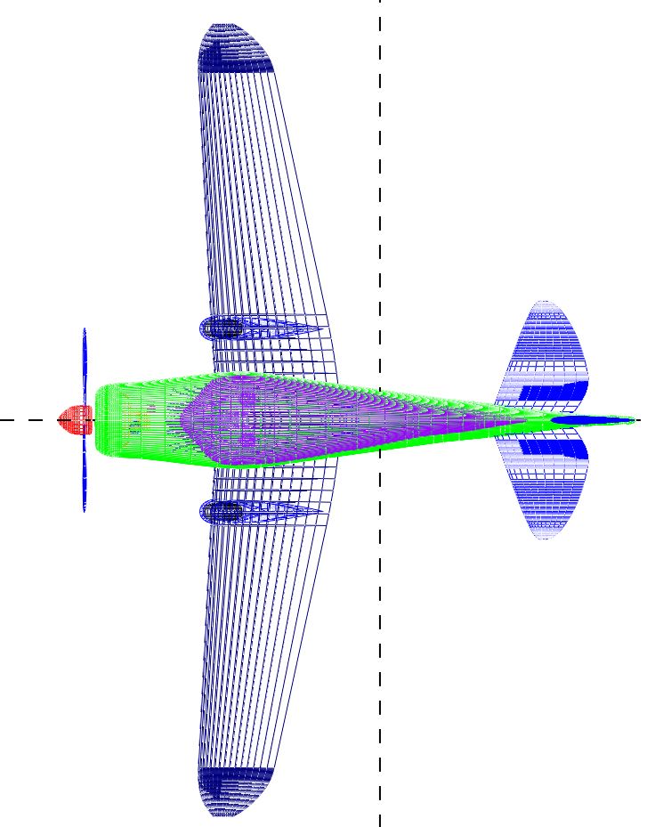
anyway here is 3 view of an earlier version of this design if anyone is interested. dimensions are the same

once again thanks for the tips,
Michael
Rob McDonald
Jan 24, 2013, 12:54:36 PM1/24/13
to ope...@googlegroups.com
Michael,
I agree that VSP's documentation is pretty lacking in spots. We try
to make things easy enough that you can figure them out with trial and
error, but often if you've found a solution that works, why would you
try doing it a different way. Please ask all the questions you like,
and if there is a particular sore spot in the documentation, take a
stab at improving the Wiki.
CFD is a peculiar tool. It is extremely powerful for some things, but
equally feeble for other things. When it comes right down to it,
predicting drag for real airplanes is one of those things that CFD is
surprisingly bad at. Your goal of teaching yourself CFD is a noble
one -- and it may be a good way to start learning the weaknesses of
CFD.
If you'd like me to detail some of the difficulties you might face,
let me know. I don't want to kick the horse unless it is warranted...
One thing that CFD might help with on this design is that nasty pinch
point between your upper wing and the canopy.
Composites are also a funny thing. Every year, I take my students on
numerous industry trips. At every stop, we get the full range of
conflicting opinions on composites... From "Composites cost more, but
we use them to save weight" to "composites are about a wash in weight,
but we use them to save cost". Both of these statements can be true
-- and understanding why/how they can both be true is central to the
use of composites (carbon, glass, kevlar, or wood).
Aerospace grade wood costs a lot more than lumber yard wood. I also
think you'll find that raw materials are a fairly small fraction of
the cost of an airplane. Buy-to-fly ratio, tooling requirements, and
touch labor can each cause dramatic swings in the cost for various
construction techniques. I can go into more detail here too, but I'll
hold off unless you ask.
Good luck with everything,
Rob

dome...@gmail.com
Mar 3, 2013, 11:39:53 PM3/3/13
to ope...@googlegroups.com
Rob,
I am a aero engineering stuent and i have just found these two great open source software. i would like to be able to use openvsp as a CAD and openfoam as a cfd analysis tool. has any one have had good experience with this ? . Are the models generated using openvsp of good enough quality for carrying out cfd analysis and get meaningful results ?.
Thanks for your time and help.
Dome
Rob McDonald
Mar 5, 2013, 11:11:46 PM3/5/13
to ope...@googlegroups.com
Dome,
Welcome to OpenVSP.
We have various users who are driving various CFD tools with OpenVSP.
Done right, I believe this can be done well. I have a lot of
experience with the Cart3D Euler code, but it is a bit different from
'normal' CFD codes.
This summer, I will have a student starting to work the connections to
other CFD codes. I hope to expand the general capability and my
confidence in this area. Most of this will target NASA codes and
perhaps commercial codes.
I don't have any direct experience with OpenFOAM, but I am happy to
support your efforts. A while back, I posed an OpenVSP announcement
to the OpenFOAM mailing list -- I don't know if anything came of it,
but I think there are very natural connections that could be
established.
Rob
> --
> You received this message because you are subscribed to the Google Groups
> "OpenVSP" group.
> To unsubscribe from this group and stop receiving emails from it, send an
> email to openvsp+u...@googlegroups.com.
> For more options, visit https://groups.google.com/groups/opt_out.
>
>
Welcome to OpenVSP.
We have various users who are driving various CFD tools with OpenVSP.
Done right, I believe this can be done well. I have a lot of
experience with the Cart3D Euler code, but it is a bit different from
'normal' CFD codes.
This summer, I will have a student starting to work the connections to
other CFD codes. I hope to expand the general capability and my
confidence in this area. Most of this will target NASA codes and
perhaps commercial codes.
I don't have any direct experience with OpenFOAM, but I am happy to
support your efforts. A while back, I posed an OpenVSP announcement
to the OpenFOAM mailing list -- I don't know if anything came of it,
but I think there are very natural connections that could be
established.
Rob
> You received this message because you are subscribed to the Google Groups
> "OpenVSP" group.
> To unsubscribe from this group and stop receiving emails from it, send an
> email to openvsp+u...@googlegroups.com.
> For more options, visit https://groups.google.com/groups/opt_out.
>
>

Ricardo Díaz
Mar 6, 2013, 2:32:38 AM3/6/13
to ope...@googlegroups.com
Hi Dome,
I've been using OpenVSP with OpenFOAM for some time now. The models exported from OpenVSP as stl file work perfect with the snappyHexMesh meshing tool of OpenFOAM.
You should only take into account to try to have a smooth surface so the layer addition process of the mesher converges good.
Ricardo Díaz.
Michael Stalls
Mar 15, 2013, 5:18:17 AM3/15/13
to ope...@googlegroups.com
Hi Rob,
On Friday, January 18, 2013 6:56:12 PM UTC+11, Michael Stalls wrote:
i have uploaded a revision of my original MH1 design. As you suggested i have changed the wings and tail to HWB and the fuselage to a Fuse 2. this has cleaned up the model considerably. i have also added some other components such as fuel tanks, oil tanks and a battery. i also decided to change the main wing airfoils to the GAW - 1. i have run compgeom on this design and it appears to work.
now i am trying to do some detailed text book analysis.
regards
michael
On Friday, January 18, 2013 6:56:12 PM UTC+11, Michael Stalls wrote:
Michael Stalls
Apr 26, 2013, 5:14:05 AM4/26/13
to ope...@googlegroups.com
Hi all,
i am trying to write up an excell spreadsheet to perform a basic textbook analysis of some of the light aircraft concepts i have designed. i am trying to write something that will calculate an initial estimate of drag, lift, CofG and performance (stall speed,max speed,range endurance etc) as well as basic stability and control and control sizing for subsonic light aircraft. i can get compgeom to work and produce wetted areas for a basic drag build up but i have a few questions on interpreting some of the other outputs. here is the model i am trying to analyse
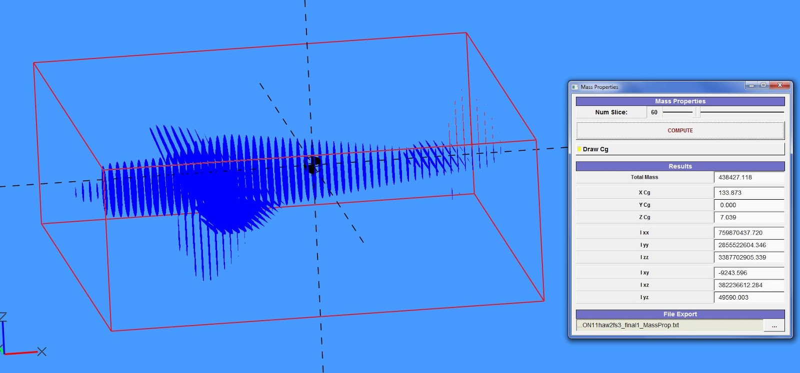
Here is a screen grab from the Mass properties function. How does VSP calculate the C of G? as can be seen from these screen grabs the position of the C of G does not look quite right. Does it just provide the geometric cofg of each individual component?
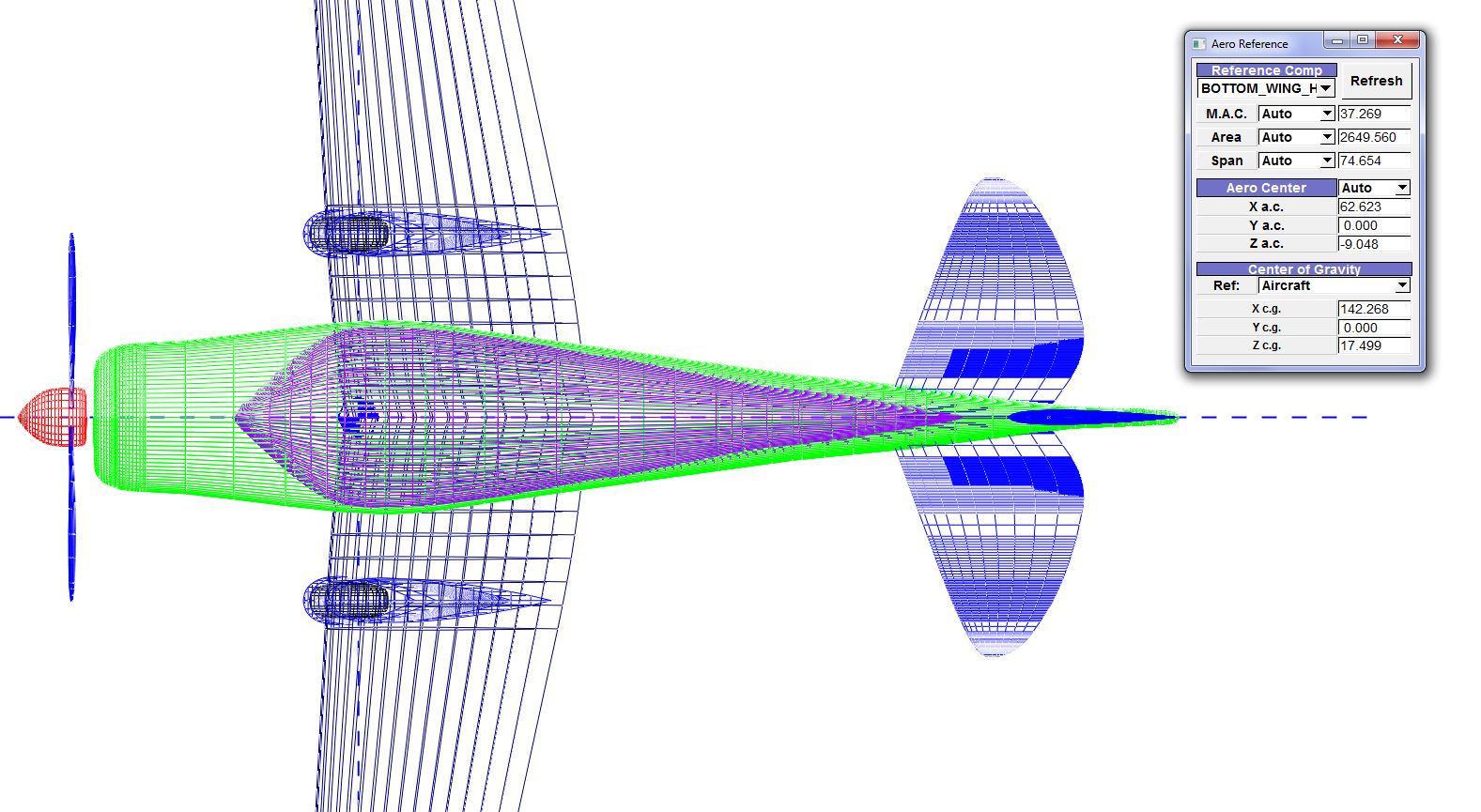
here is a screen grab of the aero reference outputs. I am not quite clear on how to interpret these outputs. The picture above is showing the aerodynamic center of the main wing what do the area and the span represent? they do not correspond to values for the wing in the HWB input. i will up load his model to the hangar if anyone is interested.
Best Regards
Michael
Rob McDonald
Apr 27, 2013, 2:57:51 PM4/27/13
to ope...@googlegroups.com
Michael,
VSP's CG and Aero Reference tools are very simple at this point.
The CG calculations should be accurate, but they are a little tricky
to fully understand. First, you have to tell VSP what every component
is made of. Under the 'XForm' tab, you can set some 'Mass Properties'
inputs. For solid objects, you set the density (mass/volume) of the
material of that object.
If you don't want to treat the object as a solid, you can also treat
it as a think shell. Click the thin shell button, and then specify
the density in terms of area (mass/area -- think of this as
thickness*mass/volume).
In addition, there is the 'Priority' number. This number determines
which density is used for an area of volume where two components
overlap. Imagine a wing-fuselage combination, where the wing is made
of foam and the fuselage is made of lead. When VSP does the
intersection calculation, it figures out that there is some volume at
the root which belongs to both the wing and the fuselage. The
Priority number tells VSP whether to count that volume as lead or
foam.
You can also add point masses to 'Blank' components. These are useful
for specifying the known mass of objects you might include -- engines,
radios, etc.
My suggestion is to build some simple models and experiment with the
density and priority settings. You'll get a hang of how the mass
properties calculations work -- and will then be able to apply them to
something complex like an aircraft.
The Aero Reference calculations are based on only a single lifting
component. They are also based on simple geometric calculations --
not comprehensive aerodynamic calculations.
So, for example, if you select the wing (vs. the tail) for Aero
Reference, the results do not change if you move or re-size the tail,
move or delete the fuselage, etc. The results only depend on the
wing.
The 'Center of Gravity' area of the 'Aero Reference' window really
treats CG as an input (not a calculation). The idea is that the
'AeroReference' window would be where a user would specify all of the
reference quantities to use in a subsequent aerodynamics calculation.
Rob
On Fri, Apr 26, 2013 at 2:14 AM, Michael Stalls
<michael...@gmail.com> wrote:
>
>
>
> Hi all,
> i am trying to write up an excell spreadsheet to perform a basic textbook
> analysis of some of the light aircraft concepts i have designed. i am trying
> to write something that will calculate an initial estimate of drag, lift,
> CofG and performance (stall speed,max speed,range endurance etc) as well as
> basic stability and control and control sizing for subsonic light aircraft.
> i can get compgeom to work and produce wetted areas for a basic drag build
> up but i have a few questions on interpreting some of the other outputs.
> here is the model i am trying to analyse
>
>
> Here is a screen grab from the Mass properties function. How does VSP
> calculate the C of G? as can be seen from these screen grabs the position of
> the C of G does not look quite right. Does it just provide the geometric
> cofg of each individual component?
>
> calculate the C of G? as can be seen from these screen grabs the position of
> the C of G does not look quite right. Does it just provide the geometric
> cofg of each individual component?
>
> here is a screen grab of the aero reference outputs. I am not quite clear
> on how to interpret these outputs. The picture above is showing the
> aerodynamic center of the main wing what do the area and the span represent?
> they do not correspond to values for the wing in the HWB input. i will up
> load his model to the hangar if anyone is interested.
> Best Regards
> Michael
>
>
Michael Stalls
Aug 3, 2013, 8:21:28 AM8/3/13
to ope...@googlegroups.com
Hi all Still working away on my project!
anyway i have uploaded 3 new models. the first is a revised version of my original biplane with rounded wings i have been sizing this using a spreadsheet someone sent to me that was originally written by the EAA for the preliminary performance and weight estimation of homebuilt (and designed) aircraft.
It gives an estimated
top speed of 150kts
stall speed of 39kts
max rate of climb 1499 feet/min (fixed pitch prop)
best Lift/drag 68 kts
gross weight of 1465lbs
and empty weight of 915lbs
the weight estimates are based on statistical methods for aluminium structures as these are the most accurate. the spreadsheet also calculates the aircraft CofG. in the MH1 model i have also included a small red pod whose length represents the CofG limits as calculated by the spreadsheet. The values look about where you would expect the cofg to lie for an aircraft of this configuration. i have also included in the MH1 model weight estimates of each component of the aircraft which i have attached as point masses to blank components that are then attached to each respective component. i then tried to calculate the cofg using the VSP method and it still comes out looking wrong

have i attached the component mass correctly? i must still be doing something wrong. i have also attached the spreadsheet i have been using. The performance values seem a bit optimistic but not entirely unrealistic when compared to the performance of similar size and configuration aircraft. there also seems to be an error in section where it calculates the aircraft stability. Ultimately i would like to write my own spread sheet based on the references that i have that will also enable analysis of canards and other configurations too. spreadsheets such as these make powerful additions to VSP. lastly i have uploaded a straight wing version of the MH1 and a single seat version MH2.
Best Regards
Michael
Rob McDonald
Aug 3, 2013, 11:19:08 AM8/3/13
to ope...@googlegroups.com
Michael,
You've clearly made a lot of progress.
VSP has three ways to include mass of a model. Each component may be
treated as a solid, or as a thin shell. Also, 'Blank' components can
have a point mass assigned.
The solid/shell mass properties for each component are set on the
XForm tab. The default solid density is 1.0 mass/volume, and the
default shell density is 1.0 mass/area -- the shell also defaults to
'off'.
So, in addition to all of your point masses carefully arranged, VSP
included the mass of all of the aircraft components calculated as if
they are a solid, with 1.0 density.
It looks like your working units are pounds and inches, so 1.0 is
about 3x the density of steel. You will also notice that your total
mass was very high.
Since you are relying on point masses, you need to 'turn off' all the
solid and shell masses. Go through and set the solid density of your
components to 0.0. You should see a big improvement.
Rob
Michael Stalls
Aug 15, 2013, 11:46:39 AM8/15/13
to ope...@googlegroups.com
HI,
i have uploaded some revised models. It took me while to figure out that you had to attach the component mass estimation to each components C of G. VSP C of G estimations now correspond to those i calculated using a spreadsheet.(and they look about right too!) now i can start thinking about doing basic longitudinal stability analysis
michael
Michael Stalls
Aug 30, 2013, 5:10:06 AM8/30/13
to ope...@googlegroups.com
Hi,
i just uploaded another model. Im now trying to make some sense of the aero reference window. for some reason the aerodynamic center calculation for the mainwing keeps coming out at the nose. it seems to work on the other models. Also what do the MAC Area and Span in the aero refernce box refer to? what is the difference between Auto and user?
regards
michael

Rob McDonald
Aug 31, 2013, 12:53:20 AM8/31/13
to ope...@googlegroups.com
The aerodynamic center calculator only does a very simple calculation based on a trapezoidal equivalent to a selected reference wing.
So, in your model, you need to pick the correct 'Reference Comp' at the top of that window. If you select WING_HWB (your main wing component) and then Referesh the computation, I think you'll see the results you expect.
'Auto' means to use the quantity as calculated by VSP. 'User' is a means for the user to override that value and type in whatever value they want. For example, if you know that the reference area used in the drag polars for an F-5 is 186 ft^2, then you can specify that independent of what VSP calculates for the model you've built.
Rob

Woon Ho "Cloud" Cho
May 31, 2016, 11:40:36 PM5/31/16
to OpenVSP
Hi, Rob McDonald;
Thanks for many information.
I am reading the OpenVSP source code at GitHub for my own computer application. Where are the center of gravity and aerodynamic center calculations in the code? Would you give me file names, so I could look into.
Thanks.
Message has been deleted

Brandon Litherland
Aug 22, 2024, 7:41:10 AM8/22/24
to OpenVSP
Cloud,
Here is the permalink to the aero center computation in VSPAERO: https://github.com/OpenVSP/OpenVSP/blob/c91a49045b70b4cd3bc96eb7ab05bb7ab77c32da/src/vsp_aero/Solver/vspaero.C#L3727
On Thursday, August 22, 2024 at 5:58:22 AM UTC-4 kudakwas...@gmail.com wrote:
Brandon Litherland
Aug 22, 2024, 7:42:10 AM8/22/24
to OpenVSP
No, no one is going to give you aircraft design Excel spreadsheets here. Also don't post unrelated questions to someone else's thread.
Message has been deleted
Brandon Litherland
Aug 23, 2024, 7:43:57 AM8/23/24
to OpenVSP
Examples of aircraft design spreadsheets are often the culmination of Graduate-level coursework or design experience spanning years. This forum is not the place to seek such resources and, at least for myself, I'd encourage you to study the foundational aircraft design texts to assemble your own code or documents. Handing someone the keys to a car without first teaching them to drive is a recipe for disaster, no? I can't know how much experience you have with aircraft design, but that's honestly irrelevant. This is not the place to seek out design codes, spreadsheets, or other resources where the work is done for you.
On Friday, August 23, 2024 at 3:02:42 AM UTC-4 kudakwas...@gmail.com wrote:
ok noted. I'm sorry for that. Would you happen to know where I can get them?

Kudakwashe Mbisva
Aug 23, 2024, 7:56:13 AM8/23/24
to ope...@googlegroups.com
Thank you for the good advice. I will try to do the work myself. Let me delete my messages from the forum. I can see that my permission to post in the forum has been declined. Is there a way to get those privileges back?
--
You received this message because you are subscribed to the Google Groups "OpenVSP" group.
To unsubscribe from this group and stop receiving emails from it, send an email to openvsp+u...@googlegroups.com.
To view this discussion on the web visit https://groups.google.com/d/msgid/openvsp/aea5d9e2-8984-493e-bdfb-c6969b4e1d87n%40googlegroups.com.
Brandon Litherland
Aug 23, 2024, 8:00:43 AM8/23/24
to OpenVSP
Your account still has posting permission as of this morning.
Reply all
Reply to author
Forward
0 new messages