Direction of prop rotation
314 views
Skip to first unread message

Peter F
Sep 28, 2021, 2:22:47 PM9/28/21
to OpenVSP
I added a prop to my model and have been able to control the direction of rotation using the 'reverse' button in the design menus. It shows counterclockwise direction from pilot viewpoint on the model.
However, when I run VSPAERO VLM with a disk instead of blades, the prop always turns clockwise. Am I missing something or is this a bug?

Rob McDonald
Sep 28, 2021, 3:00:33 PM9/28/21
to ope...@googlegroups.com
Probably would be considered a bug.
For actuator disk, you can input negative RPM and it will go the other way.
I think it automatically handles counter-rotating props when you make a symmetrical version of an off-centerline prop. However it is very likely that we miss the original Reverse flag.
Rob
On Tue, Sep 28, 2021 at 11:22 AM Peter F <nii...@gmail.com> wrote:
I added a prop to my model and have been able to control the direction of rotation using the 'reverse' button in the design menus. It shows counterclockwise direction from pilot viewpoint on the model.However, when I run VSPAERO VLM with a disk instead of blades, the prop always turns clockwise. Am I missing something or is this a bug?
--
You received this message because you are subscribed to the Google Groups "OpenVSP" group.
To unsubscribe from this group and stop receiving emails from it, send an email to openvsp+u...@googlegroups.com.
To view this discussion on the web visit https://groups.google.com/d/msgid/openvsp/48efe96d-d448-43a0-aed0-88eb12404bben%40googlegroups.com.
Peter F
Sep 28, 2021, 3:17:11 PM9/28/21
to OpenVSP
Negative rpm it is. Thanks.
Peter F
Oct 7, 2021, 9:50:53 PM10/7/21
to OpenVSP
Negative rpm worked, so now I need to make the wing AOA asymmetrical to smooth lift distribution but I want everything else symmetrical. I saw another recommendation to turn off symmetry, rotate the wing 180deg, and invert airfoils to get a completely different wing but that means every span or chord change needs to be duplicated exactly or things go bad. Is this the best method?
On Tuesday, September 28, 2021 at 12:00:33 PM UTC-7 Rob McDonald wrote:
Rob McDonald
Oct 9, 2021, 12:35:04 AM10/9/21
to OpenVSP
You can use parameter linking to link the almost symmetrical wing to the definitive version. That way, when one set of parameters changes, the other will too.
You'll want to moderate how much twist you put in to smooth the lift distribution from propulsive effects -- this kind of change will only be effective at one throttle setting.
Is it more important to have great L/D during cruise -- or during glide after an engine failure?
You will also want to make sure that you aren't cutting into your stall margin too badly -- both power on and power off. You'll have the possibility of creating some really odd lift distributions.
Lots of interesting challenges...
Rob
Peter F
Oct 11, 2021, 9:09:45 PM10/11/21
to OpenVSP
True about the effects of twist, but right now one side has negative lift so that at least has to be fixed. How realistic is the representation of swirl from the actuator disk? Some streamlines look like they might be at kind of steep angles but I don't see much of any other way to determine what the flow is doing. Excess swirl exacerbates the lift distribution problem.
I'll look into parameter linking. I saw some slides on how to do it but haven't tried it yet.
I did flip the wing and invert the airfoil, so that works. In VSAero it shows negative CL on half the wing after the solver has run, so the lift distribution looks like an S on its side. Similarly, in the visualizer the pressure gradients are on the bottom of the wing so I have to keep turning the model to see both halves. Any way to fix this?
Thanks for the help.
Rob McDonald
Oct 12, 2021, 1:15:00 PM10/12/21
to OpenVSP
Negative lift on one side of a wing may be real -- is your total net lift correct?
I suggest you increase AOA until you're near your target lift coefficient -- then check to see how the overall distribution looks.
Maybe you've already done this -- but it sounds like you might have a symmetrical airfoil at zero alpha.
Rob
Peter F
Oct 13, 2021, 8:07:52 AM10/13/21
to OpenVSP
It's a lightly loaded GAW1 at speed, so low angle of attack.
Any comment on solver or visualizer? Thanks.

Brandon Litherland
Oct 13, 2021, 11:53:34 AM10/13/21
to OpenVSP
Was the model posted somewhere else and I've missed it? Is it possible to share a working version for us to look at?
It helps to see the model itself and figure out if something is missing or if it's a bug.
Rob McDonald
Oct 13, 2021, 12:28:29 PM10/13/21
to ope...@googlegroups.com
Changing the visualization from shaded to flat often helps see what is going on on the 'bottom' of the wing.
I do not think there is an easy way to fix the visualization. OpenGL isn't really set up for lighting thin-surfaces. It expects each vertex to have an outward facing normal -- one side is lit, the other side is shadowed. Perhaps we can 'inflate' the thin surfaces and flip a normal to plot the under-side -- or something else like that. However, it is not something that will be super easy or a user-available workaround.
Similar things for the solver -- in VLM mode, it computes a deltaCp - which needs to imply an 'upper' vs. 'lower' surface. When the total forces are summed, this 'delta' is multiplied by the normal vector, so the sums should work out, but surface Cp plots can look wonky....
I'll have to think about possible solutions to this.
Rob
To view this discussion on the web visit https://groups.google.com/d/msgid/openvsp/a5374b75-2ccb-47dc-8f7e-c7c1715f5656n%40googlegroups.com.
Peter F
Oct 13, 2021, 9:18:50 PM10/13/21
to OpenVSP
Visualization to flat makes underside visible from above. This is fine for me. However, I don't know that the color/direction is consistent for both wings as the solver plot shows one wing negative, but we are looking at the 'bottom'. Do I need to think of the left wing as inverted or is the picture consistent?
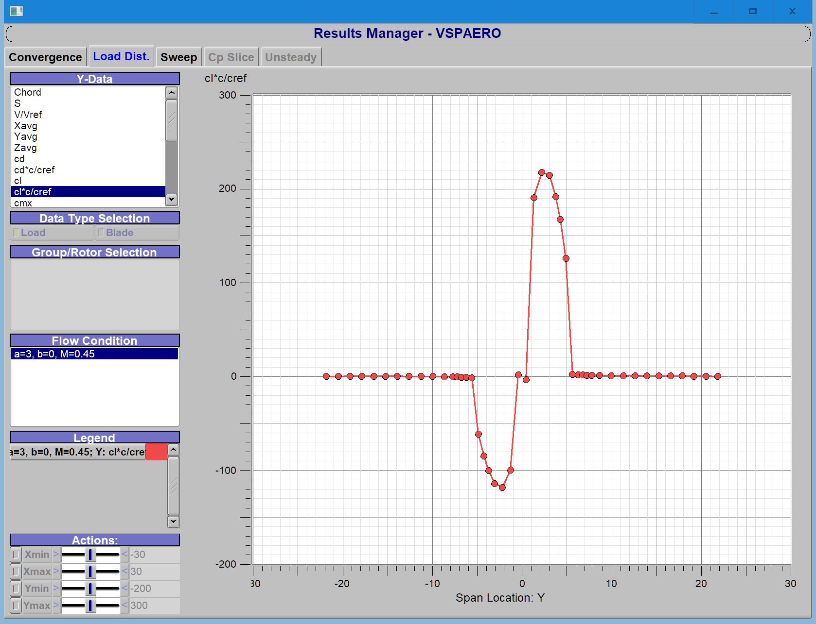
The solver also demands a zero crossover in the middle of the plot which doesn't really occur.
Here are the model and screen shots of solver and visualizer. This wing is untwisted for clarity and aoa is 3deg.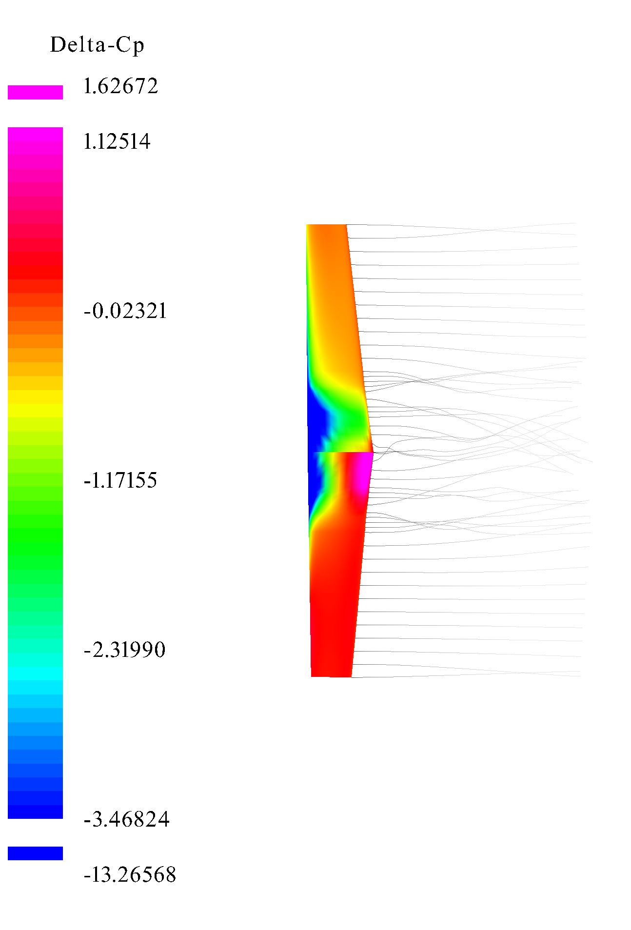
Rob McDonald
Oct 14, 2021, 1:47:18 AM10/14/21
to ope...@googlegroups.com
To experiment, I built a default wing and increased spanwise resolution -- Then I turned off symmetry and copy/pasted a duplicate and rotated that duplicate 180 about X.
I then ran it at 10 deg alpha -- no propellers.
When generating the contours in viewer, it clearly shows that the sign convention for the two wings is opposite -- one shows large negative delta Cp and the other large positive.
I have two other suggestions that may work for your situation -- they're a bit of a hassle, but may be worth it for you. In particular it depends on how many (and what kinds) of variables you want to vary in your design process.
When we started the discussion, it sounded like there was going to be a lot of focus on planform variables (strong desire to link the left and right wing halves, etc). Now it seems like there is more focus on the twist variables.
1) You could build your model with a single wing component -- starting at left wingtip, to center, to right wingtip -- but without any symmetry. You'll have 'inverted' taper on the left wing panel, then normal taper on the right wing panel. This will keep all the parts oriented properly and also give you separate control of twist on both halves of the wing.
2) You could use a single bladed propeller to represent your wing. While this is a bit of a pain, it will actually give you the greatest amount of control of camber or twist distribution -- you could have a simple straight planform with a highly nonlinear twist distribution.
I've attached a simple example that includes both approaches.
Rob
To view this discussion on the web visit https://groups.google.com/d/msgid/openvsp/67ee1a87-b5f0-4e76-a9e8-79ec0ef16ef2n%40googlegroups.com.
Peter F
Oct 14, 2021, 1:00:29 PM10/14/21
to OpenVSP
Thanks, one of these should work.
Rob McDonald
Oct 14, 2021, 1:35:41 PM10/14/21
to ope...@googlegroups.com
I just noticed -- in the bottom-right corner of the VSPAERO viewer, there is an option to flip the normal vector on any surface.
Rob
To view this discussion on the web visit https://groups.google.com/d/msgid/openvsp/c854c10b-46c3-48d7-93e1-58acc1aad115n%40googlegroups.com.
Peter F
Oct 14, 2021, 4:20:04 PM10/14/21
to OpenVSP
Nice!
Reply all
Reply to author
Forward
0 new messages