Geometric details along the span
143 views
Skip to first unread message

Reji Rejish
Nov 22, 2022, 9:33:12 AM11/22/22
to OpenVSP
Hi OpenVSP Team,
I need to compute the effective angle of attack at each wing section along the span.
Is there any way to extract/get the twist angle, dihedral angle and induced angle of attack at each station along the span?
Let me know if there exists any C++ functions to look for these values or suggest me some starting point in the code, this would be helpfull for us to merge VSPAERO with our optimisation toolbox.
Thank you very much.
Best regards,
Rejish

Rob McDonald
Nov 22, 2022, 12:41:03 PM11/22/22
to ope...@googlegroups.com
I suggest you look into the DegenGeom capability for OpenVSP. It processes a model and outputs a lot of different geometric information about it.
You'll be most interested in the 'Stick' model.
You'll be most interested in the 'Stick' model.
DegenGeom can be executed from the Analysis Menu -- where you can write out a *.csv and/or Matlab *.m file. Alternatively, you can access it from the Analysis Manager and Results Manager from the Python API. In addition, there are some helper routines in Python distributed with OpenVSP for working with the DegenGeom information.
The induced angle of attack is a part of a flow solution, I do not think VSPAERO makes it available.
Rob
--
You received this message because you are subscribed to the Google Groups "OpenVSP" group.
To unsubscribe from this group and stop receiving emails from it, send an email to openvsp+u...@googlegroups.com.
To view this discussion on the web visit https://groups.google.com/d/msgid/openvsp/51e679d5-3afc-40ff-8992-8be6956b5f42n%40googlegroups.com.
Reji Rejish
Nov 26, 2022, 4:14:42 PM11/26/22
to OpenVSP
Hi Rob,
Thanks for the details. We tried as you suggested to extract the details from DegenGeom.
However we couldn't find a way to get the downwash velocity through which we can compute the induced angle of attack.
In our work flow, we plan to use XFOIL for the profile drag computation. Therefore we need to compute the induced angle of attack.
Could you please show us some direction to proceed and explain the data's in the output file from VSPAERO "DegenGeom.case.1.quad.1.dat" and "DegenGeom.case.1.quad.2.dat"?
Are these provide downwash velocity and normal vector of the wake panel in the Trefftz plane at each section or any quad geometric details?
Best regards,
Rejish
Rob McDonald
Nov 26, 2022, 4:31:53 PM11/26/22
to ope...@googlegroups.com
The downwash velocity is not calculated by VSPAERO in a way that you need it.
Your best bet is to look at the *.lod file and to match cl instead of angle.
Rob
To view this discussion on the web visit https://groups.google.com/d/msgid/openvsp/b3e15684-95aa-4961-ac14-9937c8340737n%40googlegroups.com.
Reji Rejish
Nov 26, 2022, 8:21:44 PM11/26/22
to OpenVSP
Hi Rob,
So, I need to compute the local effective angle of attack using the local CL (at each section) then compute the profile drag using XFOIL.
Could you please point me any Reference that uses this approach?
Or is any modfication required within VSPAERO to get the downwash velocity?
This thread discussed about the survey points in space to get the velocity field (u, v, w).
Is it possible to get the downwash "w" using this approach?
Best regards,
Rejish
Rob McDonald
Nov 27, 2022, 2:07:12 AM11/27/22
to ope...@googlegroups.com
My suggestion has nothing to do with downwash.
I suggest you use the local cl reported from the VSPAERO output -- and then apply the drag contribution from whatever angle of attack gives the same cl in XFoil. By matching cl's, you match the airfoil operating condition. You ignore the angle of attack and any other angles.
Rob
Rob
To view this discussion on the web visit https://groups.google.com/d/msgid/openvsp/b9da9f7a-b3dd-46eb-8bbe-f6750625df47n%40googlegroups.com.

Brandon Litherland
Nov 27, 2022, 10:44:42 AM11/27/22
to OpenVSP
I agree completely with Rob's suggestion. XFOIL will accept Cl inputs just as readily as angle of attack. With your airfoil geometry loaded, assuming viscous mode, the process would be OPER > VISC > (set Reynolds number) > cl > 2D lift coefficient value. If you find that XFOIL is having issues converging quickly, use ITER 100 or something similar to give it more time to iterate. XFOIL is great because you can script the input/output of the runs and data using piping from the command line. For example, if you create a text file with one line representing each command line input in XFOIL, you can pipe it to the program and automate that list of commands. Let's say your file is called "airfoil.run". The command would look like this > "xfoil < airfoil.run". The airfoil.run would follow the same steps that you input in the command line interactively, including an empty line for a Return command. A very simple example running on XFOIL 6.99 is below. Note that in 6.99, activating Pacc will automatically append each run (alpha or Cl) to the output file rather that having to command PWRT at the end for the stored polar. However, this also means that it will not simply replace old files in the same session.
naca 2412
oper
visc
1e6
mach
0.3
iter 100
pacc
airfoil.out
cl 1.0
cl 1.1
cl 1.2
oper
visc
1e6
mach
0.3
iter 100
pacc
airfoil.out
cl 1.0
cl 1.1
cl 1.2
Reji Rejish
Nov 28, 2022, 5:29:40 AM11/28/22
to OpenVSP
Hi OpenVSP Team,
Thank you very much for the details. This is very interesting.
I will try this approach and let you know if I face any issue.
Best regards,
Rejish
Reji Rejish
Dec 1, 2022, 4:49:52 AM12/1/22
to OpenVSP
Hi OpenVSP Team,
I tried with XFOIL as you suggested. However, I need some clarification before proceeding further.
CL value taken from VSPAERO is invsicid (CL-inviscid).
So in my opinion, computing profile drag from XFOIL using VSPAERO's CL (instead of computing effecitve AOA from induced AOA), may give some error when estimating profile drag from XFOIL.
Is it negligible for small angle of attack?
Then it may be difficult to implement alpha-based coupling method to perform Non-Linear VLM or Hybrid solver.
Best regards,
Rejish
Brandon Litherland
Dec 7, 2022, 3:11:26 PM12/7/22
to OpenVSP
Coming back to this:
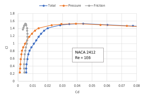
To Rob's point, by matching the local Cl you are matching the operating condition of the airfoil and therefore the wing. You are effectively saying that for a wing producing some amount of lift, inviscid or not, use XFOIL to predict the drag contributions from pressure or form drag. The friction drag is relatively independent of angle of attack and will be mostly dependent on freestream speed. VSPAERO makes an attempt at correcting for the non-linearity of the viscous component by fitting CD0 with a NACA 0012 empirical model. Circling back around, you've said that you are trying to accurately account for the profile drag of each section but haven't really stated "why". Are you using VSPAERO to compute the induced drag and supplement this value with XFOIL's viscous component? To what end? What is the end goal of your work? Why do you need an alpha-based method vs a lift-based approach? Or, instead, are you evaluating a wing design to capture spanloading and trying to use XFOIL to capture the drag...? In which case we get back to using Cl to predict Cd(total) and then integrate over the span.
Also, since you are using XFOIL I wanted to get a clarification. From the XFOIL documentation below, CD is the total drag, CDf is the skin friction drag (form drag, profile drag), and CDp is the pressure drag. Which of these values are you trying to isolate? I'm assuming the viscous friction/form drag is what you are after.
In addition to calculating the total viscous CD from the wake
momentum thickness, XFOIL also determines the friction and pressure
drag components CDf,CDp of this total CD. These are calculated by
/ _
CDf = | Cf dx CDp = CD - CDf
/
Here, Cf is the skin friction coefficient defined with the
freestream dynamic pressure, not the BL edge dynamic pressure
commonly used in BL theory. Note that CDp is deduced from
CD and CDf instead of being calculated via surface pressure
integration. This conventional definition
/ _
CDp = | Cp dy
/
is NOT used, since it is typically swamped by numerical noise.
Reji Rejish
Dec 12, 2022, 11:16:40 AM12/12/22
to OpenVSP
Hi OpenVSP Team,
Our aim is to create a aerostrutural wing optimisation framework using low-fidelity simulation tools.
For this purpose, we are using VSPAERO to compute induced drag and as Rob suggested we are now using XFOIL to estimate the profile drag (total drag) which includes both skin friction drag and pressure drag at each section and integrate along the span. So far we have reached upto this point.
As a long term plan, we need to perform a iterative viscous coupling to correct the lift contributions from a VLM solver along the span to include local viscous lift contributions using alpha based approach.
Each strip is corrected with a 2D viscous database computed
with XFOIL. If we have a induced angle of attack along the spanwise direction we can use a RANS equation solver to create a viscous database.
Is it possible to achieve the iterative viscous coupling using VSPAERO's VLM/Panel method?
Any suggestion could be useful for us to investigate with VSPAERO.
Best regards,
Rejish
Rob McDonald
Dec 15, 2022, 3:11:15 PM12/15/22
to OpenVSP
As with XFoil, I would recommend driving your 2D RANS solution to match the sectional cl. If you have different airfoils at every spanwise station, this can get a bit expensive, but it really shouldn't be too bad. In particular, if you are doing multiple alphas for the wing, you will want to create a 2D database of airfoil data by sweeping alpha and then interpolating (i.e. not running 2D CFD to match every exact point).
Rob
Reply all
Reply to author
Forward
0 new messages