Trouble implementing Kevin's Superposition of Lift paper in VSPAERO
142 views
Skip to first unread message

marc.umb...@gmail.com
Nov 21, 2022, 11:15:06 AM11/21/22
to OpenVSP
Hi All,
The issue is that it doesn't seem to work, and I can't figure out why. The output lift distribution is still off from the target by up to 20%. and appears to look for an AOA solution of 16 degrees. dCl/dalpha in VLM should be linear up to very high AOA's, should it not? In which case the theoretical basis for the paper is still valid, despite the rather high design CL specified in the script.
I wrote a script trying to implement Kevin Lane's superposition of lift paper from 2010:
DOI: 10.2514/6.2010-1227
Script :
The issue is that it doesn't seem to work, and I can't figure out why. The output lift distribution is still off from the target by up to 20%. and appears to look for an AOA solution of 16 degrees. dCl/dalpha in VLM should be linear up to very high AOA's, should it not? In which case the theoretical basis for the paper is still valid, despite the rather high design CL specified in the script.
I wonder if I'm implementing the AOA term described in the paper incorrectly. It is not as explicitly described as the w terms, and I'm curious if the wing root incidence is interfering with the AOA variation (although, with a linear addition of terms, it shouldn't be a problem).
Am I implementing this wrong in some way?
Attached is the base file that the script operates on.

Rob McDonald
Nov 21, 2022, 12:25:34 PM11/21/22
to ope...@googlegroups.com
I haven't had a chance to try running it yet, but my first guess is the use of both alpha and root incidence.
Assuming you're controlling the twist of all the wing sections (and root incidence and alpha) then you should end up with a matrix with one row that is not linearly independent. I.e. the same effect as one degree alpha could instead be achieved by a one degree deflection of all the twist variables. You should be able to check the matrix's condition number to see if anything suspicious shows up.
I would keep alpha, but drop the root incidence. Later, you might want to set a constant value of root incidence -- but I would still keep alpha.
If you sample the load distribution at more stations than you have twist variables, you'll need to solve the system in a least squares sense. It should still work fine.
It looks like you're perturbing the twist angles by one degree (magnitude). This is a reasonable value. Although you are really building up a matrix of derivatives through finite differences, the responses should be linear and you do not need to set super tiny deflections. In fact, super tiny deflections will likely cause more problems than it solves.
Rob
--
You received this message because you are subscribed to the Google Groups "OpenVSP" group.
To unsubscribe from this group and stop receiving emails from it, send an email to openvsp+u...@googlegroups.com.
To view this discussion on the web visit https://groups.google.com/d/msgid/openvsp/fe404b4f-fe91-4abb-9667-5f70a97943e1n%40googlegroups.com.

Erik Olson
Nov 22, 2022, 9:47:08 AM11/22/22
to OpenVSP
I've successfully implemented Kevin's methodology in the past using OpenVSP with AVL and ASWing (e.g.
https://doi.org/10.2514/6.2020-0269 and
https://doi.org/10.2514/6.2018-4143), but I haven't tried it with VSPAero. I used a fixed AOA of 0 degrees and perturbed the cross section incidences by one degree at a time. I think I sampled the lift distribution at 2--3 times as many locations as the number of cross sections and solved using least squares, otherwise you get large perturbations in twist trying to match the exact solution. I didn't sample the lift distribution near the tip since you don't have any control there. The method proved to be very robust and could converge from an untwisted wing to the optimum in one step.
marc.umb...@gmail.com
Dec 8, 2022, 12:57:53 PM12/8/22
to OpenVSP
Hi Erik,
I think I may see the issue.
I'm sampling at M positions, and also twisting at M positions (and these twist stations are biased towards the wingtips). There are N basis functions, and I've tried N > M and N < M. Should I be twisting independently from twist stations?
Rob McDonald
May 23, 2023, 3:58:08 PM5/23/23
to ope...@googlegroups.com
Marc,
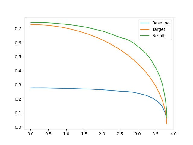
I'm playing with your twist optimization program from GitHub. I made some trivial changes to plot the resulting lift distribution.
I've tried changing the N parameter from 6 to 12 to 120 -- it seems to make no difference.
I would exect the final match to be much better. Is this similar to the results you are getting? Am I doing anything wrong with the example?
Thanks for any advice,
Rob
To view this discussion on the web visit https://groups.google.com/d/msgid/openvsp/5ccc6fdf-7f82-4a44-b194-a717133e1fd2n%40googlegroups.com.
marc.umb...@gmail.com
May 24, 2023, 5:45:39 AM5/24/23
to OpenVSP
Yeah that looks about right. I capped out at about e=.91, which i felt was sufficient for my needs. I didn't plot the lift distribution, so I didn't notice that I was overshooting the target lift curve. Any ideas?
Sincerely,
Marc
Rob McDonald
May 24, 2023, 11:49:31 AM5/24/23
to ope...@googlegroups.com
I suspect it is something with the use of the RBF's. When using OpenVSP's definition of twist, that seems to just add a ton of overcomplication -- I'm not sure what the code is doing there.
When Kevin Lane did his original version, he was twisting the wing 'outside' of OpenVSP. In that way, if a wing was tessellated into 50 panels, you could control twist at all 50 individually. It made sense to use RBF's to have fewer control variables and ensure they behaved in a smooth manner.
In OpenVSP, the example wing is divided into about five segments -- so there are only five places to control twist.
Rob
To view this discussion on the web visit https://groups.google.com/d/msgid/openvsp/b3ec3f1d-37a0-401d-9c1e-bdf9dccf30den%40googlegroups.com.
Rob McDonald
May 24, 2023, 6:57:27 PM5/24/23
to ope...@googlegroups.com
I tore the code down to the minimums and got it to work. Here is a result more like what I was expecting...
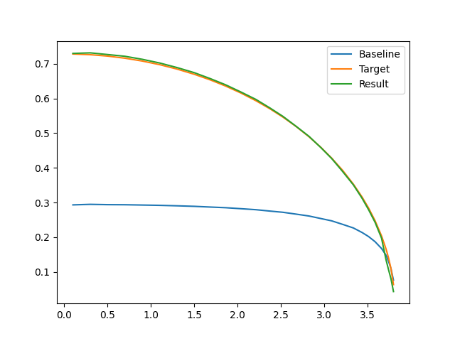
I'll push up my modifications to the script in a bit.
Rob
marc.umb...@gmail.com
May 25, 2023, 2:01:23 PM5/25/23
to OpenVSP
Thank you so much!
I'm going to look over it and see where I went wrong.
marc.umb...@gmail.com
May 26, 2023, 5:41:53 PM5/26/23
to OpenVSP
So If i'm reading it right, rather than doing an RBF, you simply give a 1 degree twist at each station individually, and N = m_stations?
Rob McDonald
May 26, 2023, 5:48:10 PM5/26/23
to ope...@googlegroups.com
Yes. I think I skip twisting the 0th section (root incidence) because since alpha is included, you can't distinguish twisting all (including 0) from just alpha.
So for a 7 segment wing, that gives us 8 variables (7 twists + alpha).
The wing tessellation is about 5 per segment, so that leaves us with about 30 points observing the load distribution.
So the matrix ends up about 8x40 -- leaving plenty of redundancy for the least squares.
Rob
To view this discussion on the web visit https://groups.google.com/d/msgid/openvsp/0c135d91-1d3d-4522-82aa-ee93f7e56c6dn%40googlegroups.com.
marc.umb...@gmail.com
May 27, 2023, 3:52:16 AM5/27/23
to OpenVSP
That was the trick I wasn't getting ! I was looking at M as the number of controlled wing stations, not the number of tessellation points!
Reply all
Reply to author
Forward
0 new messages