Peter Betz's Head- Revision 1 and 2

Peter Betz
Sorry I have been pretty quiet lately. Things are still chugging away in the background. First of all, this is a continuation of the original head design found here:
https://groups.google.com/forum/#!topic/openpnp/-XGpRTdaTrk ("Head Thread")
The design is perfectly fine and lends itself well to laser cut acrylic (or delrin if you are super fancy). My machine is currently running this head.
I decided to make a couple of improvements to the design (and change the default material to aluminum), enter REVISION 1:
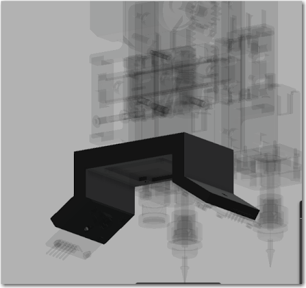
1. New designed top plate with cable chain attach points:
The top plate has been designed as a stronger method of attaching the cable chain. The chain exerts more force on the head than I expected! This design also allows mounting holes for components on top of the head.
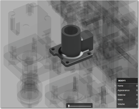
2. New vacuum gaskets:
In an attempt to improve Anthony Webb's gasket design, I have changed it to allow for screwing in a NPT push-to-connect fitting (for 4mm or similar vacuum line).
3: Integrated belt tensioners:
With integrated nut traps and everything being cut out of stock 1/4" material (waterjet or laser) this simplifies the design by removing the need to drill and tap the side faces to attach brackets. Special thanks to Mark Harris for helping zero in on the final design.
4. Away with the opto switch and fragile thin feature.
In order to make the design more robust, I decided to try using a high quality snap action limit switch instead. This makes the design slightly more compact and also does away with that very thin interrupter feature. Using contact sets in Fusion I was able to simulate the tripping of the switch and find the ideal mounting angle for it! These switches are rated for millions of cycles MTBF, so I consider this to me a long term, reliable solution.
5: I had a strong desire to try and integrate Z probing.
First, there was to be two plates at the bottom of the NEMA8 steppers. The upper plate is fixed to the stepper motor mounting screws and the bottom is fixed to the toothed plate attached to the linear rail. Motion is supported between the two plates along 4 precision ground shoulder screws:
Then, a new designed vacuum gasket would allow for contact with a microswitch:
Here is a GIF showing how it was designed to function:
Mark went ahead and had it cut on the waterjet to prototype. Long story short is that the required tolerances on the shoulder bolt holes is too great and would require a more precise manufacturing method, like CNC milling to maintain part placement accuracy. Unfortunately I don't think that it will be worth pursuing this method any further :(
Revision 2 is only modifying the Z probe style.
My new thought is to have the Z stepper completely unrestrained in its rotational axis (no mounting bolts securing it). The stepper shaft would pass though a flanged bearing in the main plate, and the stepper face would press up on a caged bearing. There would be a printed washer that went under the gear to allow the stepper to be drawn in to the head plate using the set screw on the gear (if that makes sense). Here is a simple mock-up:
The stepper motor would only be restrained in rotation by the contact force of two microswitches mounted on the back of the main plate:
In the normal course of operation, the only force that would be exerted on the switches is from acceleration, because the head is balanced. When the nozzle contacts something that provides resistance, it overcomes the contact pressure of the switch and it triggers.
Where we are at right now is proof of concept. I have a full set of metal parts here, and I have some switches with about the lowest contact pressure available. I am going to take my head apart and build it up with the new metal parts and also make a small 3D printed shoulder bushing to restrain the Z stepper similar to how the bearings would. I can then actually see the result on my machine and see if this method is viable. I actually have pretty high hopes for this. Any of the play in the Z system is not really that important with the spring loaded nozzles, at least that's how I feel about it!!
Now, thanks to Mikael, I really need to step up my rendering game.... sigh.
That's all for now, hope you guys like the changes.
Peter.

Michael Anton
5: I had a strong desire to try and integrate Z probing.
First, there was to be two plates at the bottom of the NEMA8 steppers. The upper plate is fixed to the stepper motor mounting screws and the bottom is fixed to the toothed plate attached to the linear rail. Motion is supported between the two plates along 4 precision ground shoulder screws:
Then, a new designed vacuum gasket would allow for contact with a microswitch:
<snip>
Peter.

bobgee...@gmail.com
You have been quiet, but not idle!
Great progress, many neat additions. Loosk like the Z-probing still needs some testing / thought and Micheal's idea sounds interesting to me.
Where I am right now with my machine, I think I should try and get the basic V1 parts cut and look at upgrading to something with Z-probing at a later date. I have plenty to be getting on with anyway!
With that said, is it possible for me to get the files for the V1, without any Z-probing so I can get a set manufactured? I am also intererested in your camera + LED mount, are the designs for that available somewhere too?
I guess it is criticial to use 1/4" stock without modifying the design (i.e. the finger joint for the cable chain plate, and the belt tensioner bar are cut for 1/4" slots). If I did want to go for a thicker acrylic, are there any other places in the design I would have to adjust?
Well, thanks for all the progress, and good luck with the Z-probing!
Regards,
Bobby

Daniel Dumitru
--
You received this message because you are subscribed to the Google Groups "OpenPnP" group.
To unsubscribe from this group and stop receiving emails from it, send an email to openpnp+unsubscribe@googlegroups.com.
To post to this group, send email to ope...@googlegroups.com.
To view this discussion on the web visit https://groups.google.com/d/msgid/openpnp/b01b160d-3806-4672-9b40-20bf2102540e%40googlegroups.com.

Gregory Davill
Some random thoughts for z-probe:
I've been thinking it may be possible to utilize "stall detection" from Trinimatic TMC2130 Drivers. But a hardware solution will probably be more reliable.
Any reason why a straight vacuum sense wouldn't work for the z-probe though? Feed the value through a simple window comparator for logic level output?
Would love to see how your axially supported stepper turns out.
On Wednesday, November 16, 2016 at 6:57:02 PM UTC+10:30, Daniel wrote:
Thank you PEter ! Those revisions can be made still from acrylic ?
On Wed, Nov 16, 2016 at 10:06 AM, <bobgee...@gmail.com> wrote:
Peter,
You have been quiet, but not idle!
Great progress, many neat additions. Loosk like the Z-probing still needs some testing / thought and Micheal's idea sounds interesting to me.
Where I am right now with my machine, I think I should try and get the basic V1 parts cut and look at upgrading to something with Z-probing at a later date. I have plenty to be getting on with anyway!
With that said, is it possible for me to get the files for the V1, without any Z-probing so I can get a set manufactured? I am also intererested in your camera + LED mount, are the designs for that available somewhere too?
I guess it is criticial to use 1/4" stock without modifying the design (i.e. the finger joint for the cable chain plate, and the belt tensioner bar are cut for 1/4" slots). If I did want to go for a thicker acrylic, are there any other places in the design I would have to adjust?
Well, thanks for all the progress, and good luck with the Z-probing!
Regards,
Bobby
--
You received this message because you are subscribed to the Google Groups "OpenPnP" group.
To unsubscribe from this group and stop receiving emails from it, send an email to openpnp+u...@googlegroups.com.
To post to this group, send email to ope...@googlegroups.com.

Matt Brocklehurst
To view this discussion on the web visit https://groups.google.com/d/msgid/openpnp/0f0222ca-a498-4656-84e1-ebb1119d0ca0%40googlegroups.com.

Trampas Stern

Mikael Bohman
Peter Betz
@ Mike: That is an interesting idea for sure, not sure I am sold on the probable reliability though, especially reading through a tube.
@ bobby: I guess you mean revision 1 files. I will see about amending my Github with them. R1 does have Z probe features so you would have to work around them, like bolting the two plates together under the stepper. I believe you have to use 1/4 if you want everything to line up smoothly.
@ daniel: yes, 1/4" thick.
@ Gregory: It will be interesting to see where all of that ends up, i have been trying to pay attention to it. Vacuum sense will suck small parts up out of the feeder before the nozzle gets there.
@ Matt: For setup, all of the part feeders, like using strip feeders stuck to the deck, all must have their Z heights set. Its a bit of a pain. I can't see how this doesn't apply to you. The Z height of all part locations (any kind of feeder, but more variable for tape stuck to the bed) and the board must be set. Do you have a PnP that is running OpenPnp? I'm sure commercial machines just know the feeder heights because their location is repeatable and accurate, never seen one in person though.
@ Trampas: Having the head go to extents to find midpoint is risky, it can collide with something underneath the nozzles. You want to be able to home the dead before homing in X and Y. Using the feedback for probing is certainly promising, no one has gotten that far, as far as I know.
Peter.
bobgee...@gmail.com
Thanks for the info. About amending your github, are you saying you need to put the files there, or you need to edit the files that are there?
I am wondering how much effort it would be for me to edit the file to work with metric stock sizes available in europe. I guess I only have to modify the finger joint for the cable chain plate, and the cut out in the belt tensioner bar. Are there any other places in the design I would have to adjust?
Also, about bolting the Z-probe plates together, will this be easy for the parts as they are (i.e. is there room for bolting them together with Nema 8 installed, or again, would it be easy for me to make some modifications?
Cheers,
Bobby

Malte R.
I really like the head design and I am considering to add this to my (already modified) LitePlacer.
I don't want to sound disgraceful, but could you (or someone else who has the software and skills) modifiy the design for metric?
1/4" (6,35 mm) stock is hard or impossible to get in most parts of the world.
6mm is common in Europe, 8mm might also be available. 7mm is difficult already. 6,35mm usually has to be custom milled and thus is unaffordable.
Thanks and best regards
Malte
Peter Betz
https://github.com/BETZtechnik/ICEpick--Direct-drive-pick-and-place-head/wiki/CAD-files
I did this quickly, there are likely errors. Let me know if you find any. I changed the NEMA8 plates to allow M3 tapped threads and screws to hold the plates together,
Peter.
bobgee...@gmail.com
I (and I am sure others) am very grateful you have made the necessary changes for 6mm stock.
I am sorry to keep bothering you but I still have some questions, hopefully very simple ones for you:
On the last point, I noted that Mark Harris is now offering cheap waterjetting in Aluminium, and if this is the case would be great to remove the need for tapping before people starting spending big money on Aluminium parts. This brings another complication in that Mark is offering to cut 1/4" stock and you have just modded it all to 6mm so you might end up with two versions. Sorry if this gives you a headache, it wasn't my intention!
Anyways, really appreciate your help, gonna start talking to people about getting some parts cut now, very excited. I am hoping to have all my gear before Christmas as I have a little break then when I want to get the basic machine built and motors turning at least.
Cheers,
Bobby
Peter Betz
Do you have a specific part number for the swich you have in mind? This is the swithc with the wheel on the arm. Just want make sure I order the correct part as I know they have different arm lengths and contact forces etc.
Will you by any chance be selling your custom LED pcb for the camera system? Would be nice if I could get 4 of these, or even just the pcb when you order a few for yourself (assuming you haven't).
Yes I can certainly do that. I had lots of the PCB's made, so I can put them on the website. Do you have a printer or would you want the printed parts too?
Is the larger Motor a NEMA 17?
Yes.
Is this a MGN12H block? If not, I suppose the more generic question is what are the pitches in X and Y of the mounting holes? Sorry if it sounds like a lazy question, but I don't know how to measure anything in the autodesk viewer (web browser).
I was also wondering how close are you to doing another run of quick change nozzles? I didn't get in on the last bacth becuase I couldn't afford at the time, but have just about go it in my budget now. Any idea how soon I might get a pair if I order?
The NEMA8 I currently have, has the wiring connector at the other end, i.e. at the front of the motor. It is a mirror image of this. It is not totally clear from the model if there would be clearance or not for the connector in the cut out hole or not. I might order a different NEMA 8 to be safe, but thought I would ask for your thoughts on whether it might fit or not if you have a physical copy in your hand.
Regarding the M3 tapped holes. Looking at this view, it looks like there might just be room for a small headed m3 bolt at the rear mounting holes negating the need to tap holes. What do you think? If so, I wonder if it would be a 1 minute job to move the holes toward the front out a mm or two so there is no tapping reqired? Is that possible do you think?
On the last point, I noted that Mark Harris is now offering cheap waterjetting in Aluminium, and if this is the case would be great to remove the need for tapping before people starting spending big money on Aluminium parts. This brings another complication in that Mark is offering to cut 1/4" stock and you have just modded it all to 6mm so you might end up with two versions. Sorry if this gives you a headache, it wasn't my intention!
Peter,
Peter Betz
Peter.
Peter Betz
--
You received this message because you are subscribed to a topic in the Google Groups "OpenPnP" group.
To unsubscribe from this topic, visit https://groups.google.com/d/topic/openpnp/qdB5XmdrgOA/unsubscribe.
To unsubscribe from this group and all its topics, send an email to openpnp+u...@googlegroups.com.
To view this discussion on the web visit https://groups.google.com/d/msgid/openpnp/CAPU3koOvvtw4U2SzS6jbfGALYBg_P0uc2NtFoneixF4OCOXVrg%40mail.gmail.com.
<Peter Head R1.svg>
Daniel Dumitru


Peter Betz
On Saturday, November 19, 2016 at 9:51:03 PM UTC-8, Daniel wrote:
you made me jealous ! I will ask for a waterjet quotation locally ...By the way , have you cut the pulley as well ? or is for testing purposes only ?
It was a test of sorts, we have some concerns about wear with ALU on ALU.
Peter.
Daniel Dumitru
Peter Betz
On Saturday, November 19, 2016 at 10:15:39 PM UTC-8, Daniel wrote:
VEry clever ideea on this. One single concern I have : what force will bring nema17 motor on "aligned" position ?I would add some lamelar springs to keep it aligned...
It is the contact force of the switch that will keep it restrained (they are snap action switches). If additional force is required to hold the stepper stationary during normal movement, I will just keep ordering the next higher contact pressure switched (there are several in the same series).
One last image before bed:

Bob G
"Yes, that “hourglass” cut you are referring to is exactly why I wanted to move to 5 axis water jet.
--
You received this message because you are subscribed to a topic in the Google Groups "OpenPnP" group.
To unsubscribe from this topic, visit https://groups.google.com/d/topic/openpnp/qdB5XmdrgOA/unsubscribe.
To unsubscribe from this group and all its topics, send an email to openpnp+unsubscribe@googlegroups.com.
To post to this group, send email to ope...@googlegroups.com.
To view this discussion on the web visit https://groups.google.com/d/msgid/openpnp/5666ab3d-6b65-4300-884b-670fc59fff39%40googlegroups.com.
--
Daniel Dumitru
I like a lot ideea having nema17 motor holding on his ax.
Trampas Stern
Peter Betz
On Tuesday, November 22, 2016 at 9:28:35 AM UTC-8, Trampas Stern wrote:
I assembled Peter's head design and connected a Nano Zero Stepper board to see if I could detect force applied to the heads. For the test I set the hold current to around 200mA on the motor and then used a spring to press on each head.Here is a video showing that it works.
Very interesting video. So you are tracking the deviation from the intended position as opposed to the current required to hold the position?
Peter.
Trampas Stern
What I did was limit current and measure position error. The best mental picture is that the motor has two springs holding motor shaft at desired angle/position, the K constant on the springs is the current. So in normal operation you want stiff springs, but when homing you can use weak springs, lower current, so as not to damage nozzles.
betzt...@gmail.com
sent commands by openpnp)?
Peter.
Daniel Dumitru
Interesting, can you change motor current on the fly (theoretically being sent commands by openpnp)?
Peter.
--
You received this message because you are subscribed to the Google Groups "OpenPnP" group.
To unsubscribe from this group and stop receiving emails from it, send an email to openpnp+unsubscribe@googlegroups.com.
To post to this group, send email to ope...@googlegroups.com.
To view this discussion on the web visit https://groups.google.com/d/msgid/openpnp/444EE1068D9548BE97543D94FD68560C%40BETZtechnik.
Trampas Stern
On Tuesday, November 22, 2016 at 11:27:01 PM UTC-5, Daniel wrote:
or better to store some profiles in driver and apply them on beggining of movement ?
On Wed, Nov 23, 2016 at 4:12 AM, <betzt...@gmail.com> wrote:
Interesting, can you change motor current on the fly (theoretically being sent commands by openpnp)?
Peter.
--
You received this message because you are subscribed to the Google Groups "OpenPnP" group.
To unsubscribe from this group and stop receiving emails from it, send an email to openpnp+u...@googlegroups.com.
To post to this group, send email to ope...@googlegroups.com.
Daniel Dumitru
Peter Betz
The model is now fully PARAMETRIC in relation to stock thickness. I have updated the link on github,
This means that in the menu [modify > change parameters] you will be able to adjust the new "stk" expression which is default 6.35mm. If you change this value to 6mm, it will not only adjust the extrude command distances, but also MANY sketch features and joints so the model is properly rebuilt for your desired stock size. Things like bolt hole edge distances and offsets are all adjusted where required. Changing the stock thickness changed significantly more features than I thought.
This was hours of work but hopefully will make the model more user friendly for everyone.
Peter.

Erik Grönvall
bobgee...@gmail.com
Excellent, well done and thank you!
I will get in touch with Daniel about cutting me one to try out, really excited now. Looks like lots of interesting discussion on the Z-probing too, really encouraging progress!
I am so close to pushing the button on my purchases now, just want to know a couple of quick points so I make sure I get it right:
Will you be able to sell me 4x LED PCB, 2x new vacuum mount, 2x large bracket for camera and LED (I want two so I can use the same for up and down vision)? Any idea of the costs?
What voltage will the LED boards require? (I am currently planning to go for 12V everything rather than 24V but need to check that won't give me a problem with the LED).
Cheers,
Bobby
Daniel Dumitru
--
You received this message because you are subscribed to the Google Groups "OpenPnP" group.
To unsubscribe from this group and stop receiving emails from it, send an email to openpnp+unsubscribe@googlegroups.com.
To post to this group, send email to ope...@googlegroups.com.
To view this discussion on the web visit https://groups.google.com/d/msgid/openpnp/dae7284a-ca2f-4e46-9089-ef434d079f3e%40googlegroups.com.
Peter Betz
According to my system it appears as though you downloaded the wrong model.
Use the GitHub link in the post I made. Scroll down to the A360 link under "revision 1".
Peter.
Daniel Dumitru
Daniel Dumitru
Trampas Stern
Peter Betz
Hi Trampas,
I think you may be misunderstanding how both the V1
and V2 belt attachments work. In neither do the belts get held with
screws. In the original head, you use the brackets from anthony's frame
design which have slots for the belt to go through. Those are attached
to the head with bolts, which allow it to be tensioned. In both designs
you do not use tie wraps. You use small pins that the belt wraps around
and goes back through the slot.
Here is a rough image of how it works. The teeth lock as they pass through the slot:

Peter.

oliver jackson
I'm leaning towards Noulei as they are likely to be the best quality other than Misumi. Do you think that being C will matter?
I'm going to do an order at robotdigg after chinese new year for the hollow steppers and the 0.8M 16 tooth pinion gear. Anything else I should get from there for the head?
Michael Anton
Peter Betz
Email Sven at Noulei and tell him Peter Betz sent you, he will look after you :)

Anthony Webb
Sent from my iPhone
--
You received this message because you are subscribed to the Google Groups "OpenPnP" group.
To unsubscribe from this group and stop receiving emails from it, send an email to openpnp+u...@googlegroups.com.
To view this discussion on the web visit https://groups.google.com/d/msgid/openpnp/e1e8fa41-f48b-4c2f-b85e-e95d55fabcd6%40googlegroups.com.

Mark Harris
I will echo Peter in say Sven was very great to work with, would use him again without hesitation.
Sent from my iPhone
Make sure the listing says "HIWIN" or it is a replica. Overn Noulei will sell you both. C has running parallelism of 0.0007" over 500mm etc. Noulei will get you ANYTHING from Hiwin, even custom.--
Email Sven at Noulei and tell him Peter Betz sent you, he will look after you :)On Tuesday, January 17, 2017 at 3:59:38 PM UTC-8, Michael Anton wrote:Aliexpress has lots of linear guides that claim to be genuine Hiwin. You just have to search for what you are looking for, with Hiwin in the search, and make sure they are from Taiwan. One of the suppliers for genuine Hiwin on Aliexpress is Noulei. I would ask them if they have anything better than C class, if that is what you want. If you leave enough adjustability in how you mount the blocks and rails, you can probably tune out most of the problems with C class guides. Look at the Hiwin specifications to see exactly how the precision classes affect the dimensions. The running precision which you do care about, is really good for C class as well.Mike
You received this message because you are subscribed to the Google Groups "OpenPnP" group.
To unsubscribe from this group and stop receiving emails from it, send an email to openpnp+unsubscribe@googlegroups.com.
To post to this group, send email to ope...@googlegroups.com.
To view this discussion on the web visit https://groups.google.com/d/msgid/openpnp/e1e8fa41-f48b-4c2f-b85e-e95d55fabcd6%40googlegroups.com.
For more options, visit https://groups.google.com/d/optout.
--
You received this message because you are subscribed to the Google Groups "OpenPnP" group.
To unsubscribe from this group and stop receiving emails from it, send an email to openpnp+unsubscribe@googlegroups.com.
To post to this group, send email to ope...@googlegroups.com.
To view this discussion on the web visit https://groups.google.com/d/msgid/openpnp/9C0FBB14-FB87-4FEC-BCA3-56DCF6828633%40gmail.com.
oliver jackson
To unsubscribe from this group and stop receiving emails from it, send an email to openpnp+u...@googlegroups.com.
To view this discussion on the web visit https://groups.google.com/d/msgid/openpnp/CAJMBTyRydT1J_WuiFwmvLek7sLO9hRRVsE5EGz5FEhMgeEhG%2Bg%40mail.gmail.com.
Peter Betz
To view this discussion on the web visit https://groups.google.com/d/msgid/openpnp/CAJMBTyRydT1J_WuiFwmvLek7sLO9hRRVsE5EGz5FEhMgeEhG%2Bg%40mail.gmail.com.
For more options, visit https://groups.google.com/d/optout.
--
You received this message because you are subscribed to a topic in the Google Groups "OpenPnP" group.
To unsubscribe from this topic, visit https://groups.google.com/d/topic/openpnp/qdB5XmdrgOA/unsubscribe.
To unsubscribe from this group and all its topics, send an email to openpnp+unsubscribe@googlegroups.com.
To post to this group, send email to ope...@googlegroups.com.
To view this discussion on the web visit https://groups.google.com/d/msgid/openpnp/08648963-55D8-48FD-9A8E-40DEC8C9DB99%40gmail.com.

Mike Menci

On Wednesday, 18 January 2017 03:24:49 UTC+1, Peter Betz wrote:
Yes go with "very light preload" I think that's Z0?Peter.
On Tue, Jan 17, 2017 at 5:54 PM, oliver jackson <analogmon...@gmail.com> wrote:
Waiting on my first order from them at the moment for my delta printer. Good to know they can get hold of other options. I will contact Sven when they're back from their holidays as I know the order won't go through now. Glad you mentioned preload actually-does it make sense to get a light preload?
Noulei are good :) they will get you whatever class and preload you desire. C class are fine.
On Jan 17, 2017 5:32 PM, "Anthony Webb" <anthon...@gmail.com> wrote:
I will echo Peter in say Sven was very great to work with, would use him again without hesitation.
Sent from my iPhone
Make sure the listing says "HIWIN" or it is a replica. Overn Noulei will sell you both. C has running parallelism of 0.0007" over 500mm etc. Noulei will get you ANYTHING from Hiwin, even custom.--
Email Sven at Noulei and tell him Peter Betz sent you, he will look after you :)On Tuesday, January 17, 2017 at 3:59:38 PM UTC-8, Michael Anton wrote:Aliexpress has lots of linear guides that claim to be genuine Hiwin. You just have to search for what you are looking for, with Hiwin in the search, and make sure they are from Taiwan. One of the suppliers for genuine Hiwin on Aliexpress is Noulei. I would ask them if they have anything better than C class, if that is what you want. If you leave enough adjustability in how you mount the blocks and rails, you can probably tune out most of the problems with C class guides. Look at the Hiwin specifications to see exactly how the precision classes affect the dimensions. The running precision which you do care about, is really good for C class as well.Mike
You received this message because you are subscribed to the Google Groups "OpenPnP" group.
To unsubscribe from this group and stop receiving emails from it, send an email to openpnp+u...@googlegroups.com.
To post to this group, send email to ope...@googlegroups.com.
To view this discussion on the web visit https://groups.google.com/d/msgid/openpnp/e1e8fa41-f48b-4c2f-b85e-e95d55fabcd6%40googlegroups.com.
For more options, visit https://groups.google.com/d/optout.
--
You received this message because you are subscribed to the Google Groups "OpenPnP" group.
To unsubscribe from this group and stop receiving emails from it, send an email to openpnp+u...@googlegroups.com.
To post to this group, send email to ope...@googlegroups.com.
To view this discussion on the web visit https://groups.google.com/d/msgid/openpnp/9C0FBB14-FB87-4FEC-BCA3-56DCF6828633%40gmail.com.
For more options, visit https://groups.google.com/d/optout.
--
You received this message because you are subscribed to the Google Groups "OpenPnP" group.
To unsubscribe from this group and stop receiving emails from it, send an email to openpnp+u...@googlegroups.com.
To view this discussion on the web visit https://groups.google.com/d/msgid/openpnp/CAJMBTyRydT1J_WuiFwmvLek7sLO9hRRVsE5EGz5FEhMgeEhG%2Bg%40mail.gmail.com.
For more options, visit https://groups.google.com/d/optout.
--
You received this message because you are subscribed to a topic in the Google Groups "OpenPnP" group.
To unsubscribe from this topic, visit https://groups.google.com/d/topic/openpnp/qdB5XmdrgOA/unsubscribe.
To unsubscribe from this group and all its topics, send an email to openpnp+u...@googlegroups.com.
To post to this group, send email to ope...@googlegroups.com.
Peter Betz
Peter Betz
To view this discussion on the web visit https://groups.google.com/d/msgid/openpnp/ff8e0530-1b22-45f9-96bb-3b2f98aa47e8%40googlegroups.com.
Mike Menci

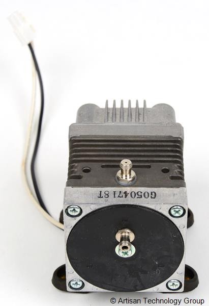
This MEDO VP0140 Linear Vacuum Pump is used and in excellent condition.
Configuration:
• Attainable Vacuum: -15.7 in.Hg
• Free Air Displacement: 0.106 cfm
• Voltage: 115 VAC/230V
Part Number: VP0140-V1006-D2-0511
Trampas Stern


Mike Menci

SMdude
Make sure your oring is not a tight fit on the shaft and make sure it is a little bit taller than the oring spacer plate so the oring squashes a little bit, pushing a bit harder on the shaft.
And use a little grease.
The way I have done it, prevents any strain (that causes your motor mount to flex a little bit) on the motor from the air hoses and motor wires.
Peter Betz
On Friday, June 2, 2017 at 10:42:27 AM UTC-7, Mike Menci wrote:
Hello Peter,Thanks for fast replyWell I am using this:
This MEDO VP0140 Linear Vacuum Pump is used and in excellent condition.
Configuration:
• Attainable Vacuum: -15.7 in.Hg
• Free Air Displacement: 0.106 cfm
• Voltage: 115 VAC/230V
Part Number: VP0140-V1006-D2-0511Which one do you recommend?ThanksMike
Hey that is a neat pump. Is it a diaphragm pump? I just use the 24v one robotdigg uses and the 3d printed vacuum gasket that Anthony came up with (I modded it to accept a push-to-connect fitting though), works great.
Peter.
Mike Menci
Wiring:
- Red - Positive supply (+24VDC)
- Black - Ground (0VDC)
- Green - Tachometer output (0-5VDC)
- White - PWM or analog control (0-5VDC)
- NOTE: PWM frequency is set by the manufacturer. Please see their documentation. Incorrect PWM frequency drive may damage the unit. Analog control means you can drive a 0-5V signal into the device and control its speed (no need to alter the supply voltage).

Jason von Nieda
--
You received this message because you are subscribed to the Google Groups "OpenPnP" group.
To unsubscribe from this group and stop receiving emails from it, send an email to openpnp+u...@googlegroups.com.
To post to this group, send email to ope...@googlegroups.com.
To view this discussion on the web visit https://groups.google.com/d/msgid/openpnp/1cbc41ac-bb88-4612-aa0e-72f0c624439c%40googlegroups.com.
Mike Menci

Jason von Nieda
To view this discussion on the web visit https://groups.google.com/d/msgid/openpnp/781f8101-3b84-4b6d-ab1e-51a6a7148070%40googlegroups.com.
Mike Menci

Friedrich Mäckle
Am Mittwoch, 16. November 2016 06:16:06 UTC+1 schrieb Peter Betz:
Hi Everyone,
Sorry I have been pretty quiet lately. Things are still chugging away in the background. First of all, this is a continuation of the original head design found here:
https://groups.google.com/forum/#!topic/openpnp/-XGpRTdaTrk ("Head Thread")
The design is perfectly fine and lends itself well to laser cut acrylic (or delrin if you are super fancy). My machine is currently running this head.
I decided to make a couple of improvements to the design (and change the default material to aluminum), enter REVISION 1:
1. New designed top plate with cable chain attach points:
The top plate has been designed as a stronger method of attaching the cable chain. The chain exerts more force on the head than I expected! This design also allows mounting holes for components on top of the head.
2. New vacuum gaskets:
In an attempt to improve Anthony Webb's gasket design, I have changed it to allow for screwing in a NPT push-to-connect fitting (for 4mm or similar vacuum line).
3: Integrated belt tensioners:
With integrated nut traps and everything being cut out of stock 1/4" material (waterjet or laser) this simplifies the design by removing the need to drill and tap the side faces to attach brackets. Special thanks to Mark Harris for helping zero in on the final design.
4. Away with the opto switch and fragile thin feature.
In order to make the design more robust, I decided to try using a high quality snap action limit switch instead. This makes the design slightly more compact and also does away with that very thin interrupter feature. Using contact sets in Fusion I was able to simulate the tripping of the switch and find the ideal mounting angle for it! These switches are rated for millions of cycles MTBF, so I consider this to me a long term, reliable solution.
5: I had a strong desire to try and integrate Z probing.
First, there was to be two plates at the bottom of the NEMA8 steppers. The upper plate is fixed to the stepper motor mounting screws and the bottom is fixed to the toothed plate attached to the linear rail. Motion is supported between the two plates along 4 precision ground shoulder screws:
Then, a new designed vacuum gasket would allow for contact with a microswitch:
Here is a GIF showing how it was designed to function:
Mark went ahead and had it cut on the waterjet to prototype. Long story short is that the required tolerances on the shoulder bolt holes is too great and would require a more precise manufacturing method, like CNC milling to maintain part placement accuracy. Unfortunately I don't think that it will be worth pursuing this method any further :(
Revision 2 is only modifying the Z probe style.
My new thought is to have the Z stepper completely unrestrained in its rotational axis (no mounting bolts securing it). The stepper shaft would pass though a flanged bearing in the main plate, and the stepper face would press up on a caged bearing. There would be a printed washer that went under the gear to allow the stepper to be drawn in to the head plate using the set screw on the gear (if that makes sense). Here is a simple mock-up:
The stepper motor would only be restrained in rotation by the contact force of two microswitches mounted on the back of the main plate:
In the normal course of operation, the only force that would be exerted on the switches is from acceleration, because the head is balanced. When the nozzle contacts something that provides resistance, it overcomes the contact pressure of the switch and it triggers.
Where we are at right now is proof of concept. I have a full set of metal parts here, and I have some switches with about the lowest contact pressure available. I am going to take my head apart and build it up with the new metal parts and also make a small 3D printed shoulder bushing to restrain the Z stepper similar to how the bearings would. I can then actually see the result on my machine and see if this method is viable. I actually have pretty high hopes for this. Any of the play in the Z system is not really that important with the spring loaded nozzles, at least that's how I feel about it!!
Now, thanks to Mikael, I really need to step up my rendering game.... sigh.
That's all for now, hope you guys like the changes.
Peter.
Peter Betz
--
You received this message because you are subscribed to a topic in the Google Groups "OpenPnP" group.
To unsubscribe from this topic, visit https://groups.google.com/d/topic/openpnp/qdB5XmdrgOA/unsubscribe.
To unsubscribe from this group and all its topics, send an email to openpnp+u...@googlegroups.com.
To view this discussion on the web visit https://groups.google.com/d/msgid/openpnp/89dce844-4c0f-45f1-857b-0e24a938a6fb%40googlegroups.com.
oliver jackson
You received this message because you are subscribed to the Google Groups "OpenPnP" group.
To unsubscribe from this group and stop receiving emails from it, send an email to openpnp+u...@googlegroups.com.
To view this discussion on the web visit https://groups.google.com/d/msgid/openpnp/41C117EE-266B-4B68-A010-956355B3E9CF%40gmail.com.
Peter Betz
--
Daniel
Peter Betz
--
You received this message because you are subscribed to a topic in the Google Groups "OpenPnP" group.
To unsubscribe from this topic, visit https://groups.google.com/d/topic/openpnp/qdB5XmdrgOA/unsubscribe.
To unsubscribe from this group and all its topics, send an email to openpnp+u...@googlegroups.com.
To post to this group, send email to ope...@googlegroups.com.
To view this discussion on the web visit https://groups.google.com/d/msgid/openpnp/4bac2b75-4155-4782-8983-94626b8e90c8%40googlegroups.com.
Friedrich Mäckle
Friedrich Mäckle
Peter Betz
To view this discussion on the web visit https://groups.google.com/d/msgid/openpnp/dddb29ba-c9f0-44ee-b3e5-2b96c2eb9a44%40googlegroups.com.
Daniel Dumitru
Trampas Stern
Peter Betz
--
You received this message because you are subscribed to a topic in the Google Groups "OpenPnP" group.
To unsubscribe from this topic, visit https://groups.google.com/d/topic/openpnp/qdB5XmdrgOA/unsubscribe.
To unsubscribe from this group and all its topics, send an email to openpnp+u...@googlegroups.com.
To post to this group, send email to ope...@googlegroups.com.
To view this discussion on the web visit https://groups.google.com/d/msgid/openpnp/75e2c9ef-80a2-483d-8504-d6fce5696418%40googlegroups.com.
Trampas Stern
Michael Anton
Trampas Stern
Friedrich Mäckle
Peter Betz
To view this discussion on the web visit https://groups.google.com/d/msgid/openpnp/aa44633a-b6c0-4bba-8443-d3d578d7ea5b%40googlegroups.com.
Peter Betz
Still waiting for the waterjet quotes but that is the last piece of the puzzle.
Peter.
Friedrich Mäckle
Peter Betz

Thomas Langås
--
You received this message because you are subscribed to the Google Groups "OpenPnP" group.
To unsubscribe from this group and stop receiving emails from it, send an email to openpnp+unsubscribe@googlegroups.com.
To post to this group, send email to ope...@googlegroups.com.
To view this discussion on the web visit https://groups.google.com/d/msgid/openpnp/0FE975A9-D97F-449E-82EE-04813B4B1DBF%40gmail.com.
Peter Betz
I'm interested in this (I have juki nozzle holders from you, already), but I'm not sure if I need to modify the top a bit. I have 80x80mm extrusion as X-axis, with a linear rail on one side, cable guides on top, an ball screw on the backside.
On Aug 21, 2017 21:13, "Peter Betz" <betzt...@gmail.com> wrote:
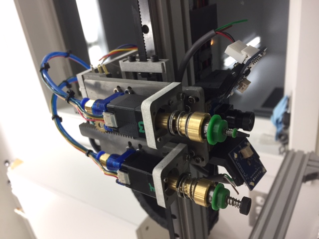
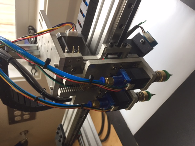
Hi Everyone,Finally I have all the pricing together!! I'm actually excited about this as I have wanted to make a batch for some time now. I have tried to make the pricing as good as possible as this is something I would like to continue doing (and I hope it is cheap enough that people who have laser cut versions would want to upgrade to metal). As I always seem to do, I have likely priced this too low, and way to tight, and next run the price will realistically be a little more, so I'd suggest taking advantage of jumping on this run of 10 heads! This will also spur me into continuing my research on Z probing which these heads will have the ability to upgrade to (just by bolting on a few parts that will fit with no mods) if it proves successful.*****************Price without our Juki Nozzle holders: $219 USD*****************Price with a set of Juki Nozzle holders: $319 USD*****************I will discuss a discount for the nozzle holders with Mark when purchased with a head but those are super expensive parts to have made, due to the tolerances, but the results are well worth it!What you will get:- One fully assembled V2 head (without the extra hardware for Z probing) complete with NEMA 17 Z axis motor, 2 NEMA 8 hollow shaft part motors, 2 linear rails, genuine micro switch for homing etc. I will even include mounting screws for the X bearing block.- waterjet from 1/4" ALU to 0.005" tolerance.- I will be fixturing the waterjet parts and CNC machining the required mating surfaces to have all the parts fit as perpendicular as possible.- I will also experiment with CNC machining a shallow pocket for the MG9 linear rails. This would create a very accurate reference edge for each rail to ensure the rails are completely parallel to each other and perpendicular to the X axis rail.* The importance of the above features really become apparent when you start dialing the machine in for smaller parts.- Fully tested ! I will be performing a variety of tests to ensure that the assembled head meets the quality I would expect if I were purchasing it. This will be especially important with the rails, more on that later.
If you order them with our Juki Nozzle holders, I will also fully test them and set the nozzle holders to the lowest possible runout configuration and ensure runout is within our specified range.Shipping would be extra but I will have economy and express options. I do not price shipping to make money, so it will be the real cost plus a little for packaging materials etc.I could also probably do custom backplates for people looking to put this on a machine that doesn't have a 12mm linear rail on the X axis. The kit will not have the 3D printed parts included by default (NEMA 8 vacuum gaskets and the camera mount) but I can look at making those available for those who are interested.Like I was saying, I'm not sure I will be doing this again for that exact price (assuming there is interest) (I'm a perpetual optimist when it comes to pricing a job :) )but I'm excited about the thought of getting this design out there made of aluminum !!! I'm hoping to get at least 4 people committed before I pull the trigger on spending a couple thousand dollars to make the 10 units.Pictures for effect:
<image1.JPG>I will also create a dedicated thread for this for those that aren't subscribed.Please indicate if you are interested. Thanks everyone!Peter BetzBetz Technik Industries Ltd.

--
You received this message because you are subscribed to the Google Groups "OpenPnP" group.
To unsubscribe from this group and stop receiving emails from it, send an email to openpnp+unsubscribe@googlegroups.com.
To post to this group, send email to ope...@googlegroups.com.
To view this discussion on the web visit https://groups.google.com/d/msgid/openpnp/0FE975A9-D97F-449E-82EE-04813B4B1DBF%40gmail.com.
For more options, visit https://groups.google.com/d/optout.
--
You received this message because you are subscribed to a topic in the Google Groups "OpenPnP" group.
To unsubscribe from this topic, visit https://groups.google.com/d/topic/openpnp/qdB5XmdrgOA/unsubscribe.
To unsubscribe from this group and all its topics, send an email to openpnp+u...@googlegroups.com.
To post to this group, send email to ope...@googlegroups.com.
To view this discussion on the web visit https://groups.google.com/d/msgid/openpnp/CANN7TQmzW--BmHJ7tjPhBYxpaa9CkGBivPV3UhNXoogGNRxyXA%40mail.gmail.com.
Friedrich Mäckle
To unsubscribe from this group and stop receiving emails from it, send an email to openpnp+u...@googlegroups.com.
To post to this group, send email to ope...@googlegroups.com.
To view this discussion on the web visit https://groups.google.com/d/msgid/openpnp/0FE975A9-D97F-449E-82EE-04813B4B1DBF%40gmail.com.
For more options, visit https://groups.google.com/d/optout.