A low-cost and high-precision feeder is about to be completed
987 views
Skip to first unread message

bing luo
Jul 14, 2022, 11:51:36 PM7/14/22
to OpenPnP
This feeder will be named 0775 feeder
The gear can rotate 2mm and 4mm accurately.This feeder only needs a high-level trigger, and the gear can rotate 2mm or 4mm accurately without any program.
You can see its movement here
From the experimental results, the accuracy fully meets the requirements, and there will be no cumulative error。I'm perfecting the 3D structure and then sharing it。
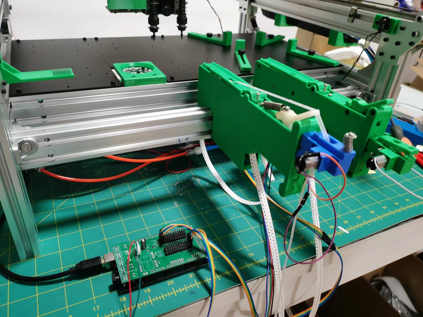
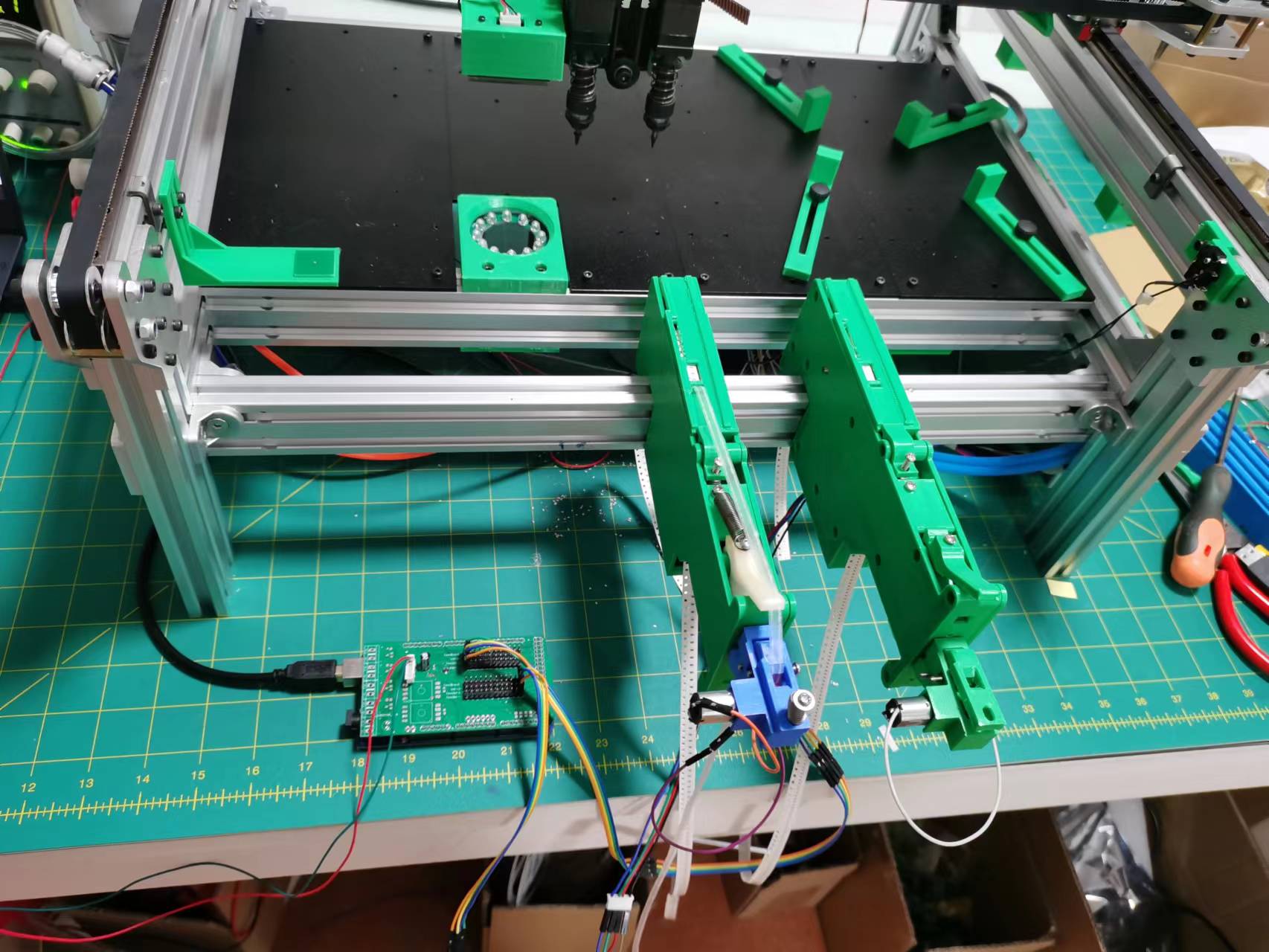
The pulling method is copied from 0816 feeder. I plan to add a worm wheel so that the N20 motor does not have to be perpendicular to the feeder。This can reduce the occupation of location.
The materials you need to prepare are:
1:N20 reduction motor *2
2:Electromagnetic relay *1
3: Switch*1 (SS-5-5GL)
4: Optical switch*1 (EE-SX670P)
5: NPN triode (8050)
6:worm wheel(1:60)(0.5 modulus) for 2mm feeder
7:worm wheel(1:30)(0.5 modulus) for 4mm feeder
8:Steel gear*1( 4mm tooth spacing, 30 teeth)
bing luo
Jul 15, 2022, 5:33:20 AM7/15/22
to OpenPnP
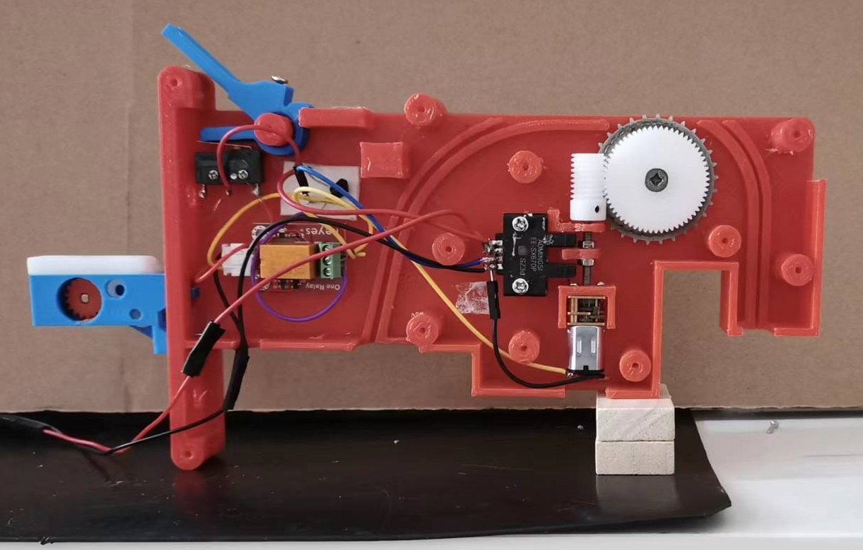
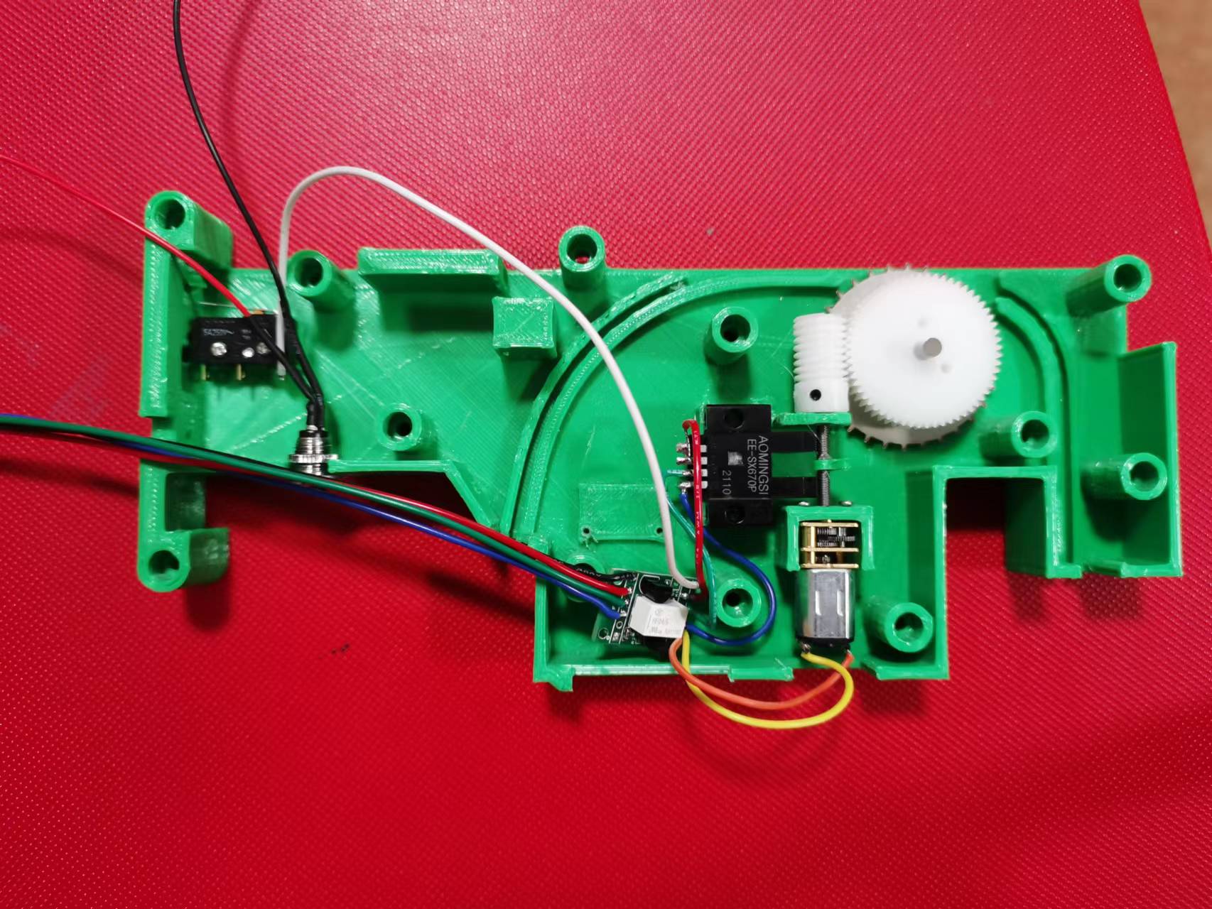
1: The optical switch(EE-SX670P) is in the normally closed state, the Output pin output 5V high level to the base of the triode(8050), and the triode is turned on. But because the electromagnetic relay is normally open. Therefore, the motor will not rotate.
2: The control board sends out a high level of 20ms(you can also send high level by manually closing ss-5-5gl). At this time, the motor starts to rotate, the light baffle also starts to rotate,and the electromagnetic relay is closed.
3: because the electromagnetic relay is closed, after the 20ms high level output by the controller disappears, the motor continues to rotate with the power supplied by the triode emitter.
4: When the light baffle rotates 360 degrees, the light switch is blocked, the voltage at the output pin becomes 0V, the triode is cut off, and the relay is disconnected due to the loss of 5V, so the motor stops rotating。
5: In this way, you can realize the precise one turn rotation of the worm gear and stop automatically. Whether the steel gear advances 2mm or 4mm depends on the reduction ratio of the worm gear and the tooth pitch of the steel gear.
.jpg?part=0.1&view=1)

Noël
Aug 2, 2022, 8:28:24 PM8/2/22
to OpenPnP
That looks great. I like the way the pick area is clear from obstacles. The 0816 feeders have the top part that can crash with the nozzle on machine that have a y offset between camera and nozzle. Your feeder fixes that problem pretty well.
Would you have some stl file we can print? Have you shared that project anywhere?
bing luo
Aug 2, 2022, 10:45:20 PM8/2/22
to OpenPnP
The following is the firmware code that can be used by 0816 feeder control,There are no changes in the hardware. Updating the firmware can support 0775 feeders.
const uint8_t Power_Control_Pin = A15; // Define power control pins
// Define motor control pins
const uint8_t Motor_Control_Pin[24] = {
13, 11, 9, 7, 5, 3,
14, 16, 18, 22, 24, 26,
30, 32, 34, 36, 38, 40,
42, 44, 46, 48, 50, 52
};
// Define feedback pins
const uint8_t Feedback_Sensor_Pin[24] = {
12, 10, 8, 6, 4, 2,
15, 17, 19, 23, 25, 27,
31, 33, 35, 37, 39, 41,
43, 45, 47, 49, 51, 53
};
uint8_t pinValue = 0; // Store Pin value
uint8_t pulseValue = 0; // Store impulse value
uint16_t cmdValue = 0; // Store command value
uint8_t rxCount = 0; // Used for serial port receiving count
char rxBuffer[200] = {0}; // Store data received by serial port
void setup()
{
Serial.begin(9600); // Initialize serial port, baud rate 9600
pinMode(Power_Control_Pin, OUTPUT); // Set the power control pin to output mode
digitalWrite(Power_Control_Pin, LOW); // Set the power control pin output low level
for (uint8_t i = 0; i < 24; i++) //
{
pinMode(Motor_Control_Pin[i], OUTPUT); // Set the motor control pin to output mode
digitalWrite(Motor_Control_Pin[i], LOW); // Set the motor control pin output low level
pinMode(Feedback_Sensor_Pin[i], INPUT_PULLUP); // Set the feedback pin to the pull-up input mode
}
}
void loop()
{
while (Serial.available()) // Cycle until no data is readable on the serial port
{
rxBuffer[rxCount] = Serial.read(); // Read one bit data
if (rxBuffer[rxCount] == '\n') // If the terminator is received
{
rxBuffer[rxCount] = 0; // Set packet Terminator
Serial.println(rxBuffer); // Print received data
Unpack_Data(); // Parse data
rxCount = 0; // Restart receiving data
}
else //
rxCount++; //
if (rxCount >= 200) // If the received data exceeds the size of the serial port buffer array
rxCount = 0; // Restart receiving
}
}
void Unpack_Data(void)
{
char *Tail = NULL, *Head = NULL; // Pointer to store parsing data
if ((Head = strchr(rxBuffer, 'M')) != NULL) // If M is found
{
if ((Tail = strchr(Head, ' ')) != NULL) //If a space character is found
{
*Tail = 0; //Truncate string
cmdValue = atoi(Head + 1); //
Serial.print(cmdValue); //
Serial.print(","); //
if (cmdValue == 610) // 610
{
if (strstr(Tail + 1, "S1") != NULL) // If S1 is searched
{
digitalWrite(Power_Control_Pin, HIGH); // Power on
Serial.print(1); //
}
else if (strstr(Tail + 1, "S0") != NULL) // If S0 is searched
{
digitalWrite(Power_Control_Pin, LOW); // Turn off the power
Serial.print(0); //
}
}
else if (cmdValue == 600) // 600
{
Head = strchr(Tail + 1, 'N'); // Find N
Tail = strchr(Head, ' '); // Find spaces
*Tail = 0; // Truncate string
pinValue = atoi(Head + 1); // Get pin number
Head = strchr(Tail + 1, 'F'); // Find F
pulseValue = atoi(Head + 1); // Get propulsion value
pulseValue = pulseValue / 4; // Convert to pulse number (4mm, 8mm, 12mm, 16mm, 24mm, using 1:30 reduction ratio turbine. Turn the vortex rod once, the gear advances 4mm,
//turn it twice, advances 8mm, and so on
pulseValue = pulseValue ? pulseValue : 1; // Convert to pulse number (2mm, using a 1:60 reduction ratio turbine. The scroll rod rotates once, and the gear advances 2mm)
Serial.print(pinValue); //
Serial.print(","); //
Serial.print(pulseValue); //
Send_Pulse(); // Send pulse
}
Serial.println(); // 打印调试信息
}
}
}
void Send_Pulse(void)
{
for (uint8_t i = 0; i < pulseValue; i++) // Cycle enough pulses
{
digitalWrite(Motor_Control_Pin[pinValue], HIGH); // Motor control pin output high level
delay(200); //Wait for 200ms
digitalWrite(Motor_Control_Pin[pinValue], LOW); // Motor control pin output low level
while (digitalRead(Feedback_Sensor_Pin[pinValue]) != LOW) // Cycle until the feedback pin is low level
;
}
}
bing luo
Aug 2, 2022, 11:01:45 PM8/2/22
to OpenPnP
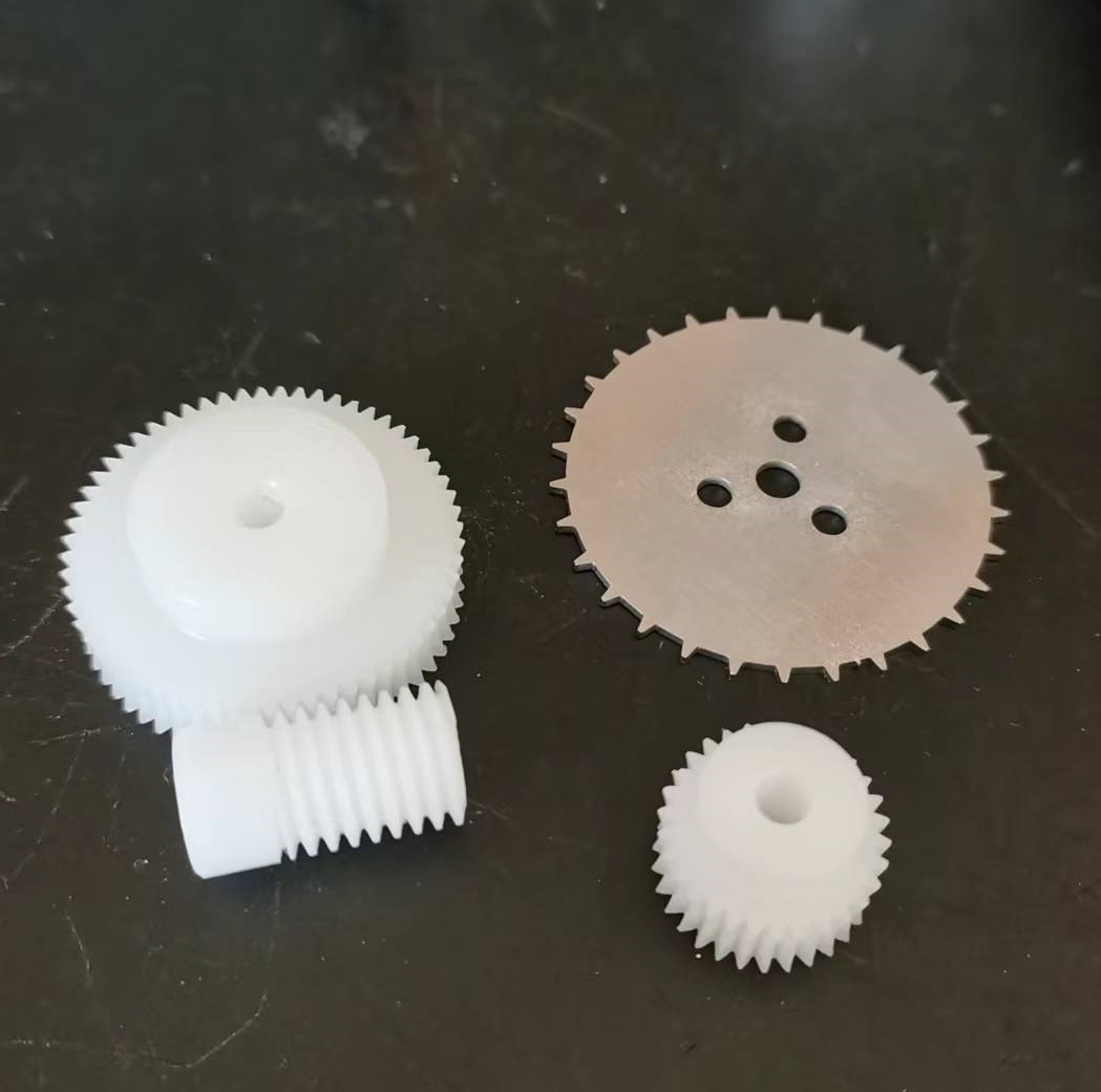
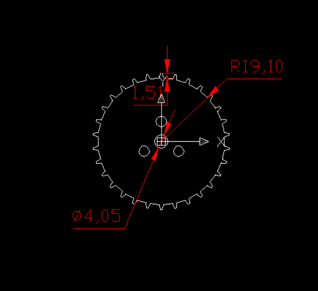
This is POM turbine and stainless steel gear I am making. You can also make them yourself according to your needs. If you has a high-precision 3D printer, it should be able to print by yourself. It requires two models. One is that the teeth are 0.5 modulus, the number of teeth is 60, and the 1:60 reduction ratio is used to drive a distance of 2mm. The other kind of teeth is 0.5 modulus, the number of teeth is 30, and the 1:30 reduction ratio is used to push the distance of 4,8,12,16,24mm. The thickness of stainless steel gear is 1mm, there are 30 teeth, the tooth height is 1.5mm, and the tooth spacing is 4mm。
bing luo
Aug 2, 2022, 11:03:14 PM8/2/22
to OpenPnP
Stainless steel gears are made by laser cutting machine, which is very cheap,
bing luo
Aug 2, 2022, 11:10:22 PM8/2/22
to OpenPnP
I still need a week to improve the information, and then share it in GitHub. In fact, this principle is too simple. You can make it yourself now.

Paul Gallagher
Nov 16, 2022, 6:53:45 AM11/16/22
to OpenPnP
Very nice. I was just working on something very similar. I was going to use 1.6mm thick PCB for the outside walls. That gives you a lot of strength and can also use for your circuit and eliminate the internal wires. The motor might be a little slow, especially if need 8 or 12mm moves. And maybe could add dipswitch for selecting 2mm, 4mm, 8mm and 12mm moves.

Mike Menci
Nov 16, 2022, 7:51:03 AM11/16/22
to OpenPnP
Can you please share .dxf file of the stainless steel sprocket ?
PCB material could be used instead of Stainless Steel for DIY use.
Mike
Mike Menci
Nov 16, 2022, 7:53:33 AM11/16/22
to OpenPnP
1mm thick PCB ! not 1.6mm!
bing luo
Nov 16, 2022, 10:12:03 AM11/16/22
to OpenPnP
A: if the stainless steel gear rotates with good concentricity, it can easily achieve 2mm advance per second (using a turbine with a reduction ratio of 60), 4mm advance per second (using a turbine with a reduction ratio of 30), and for 8mm, 16mm and 24mm advance, it is enough to let the turbine rotate a few more cycles.
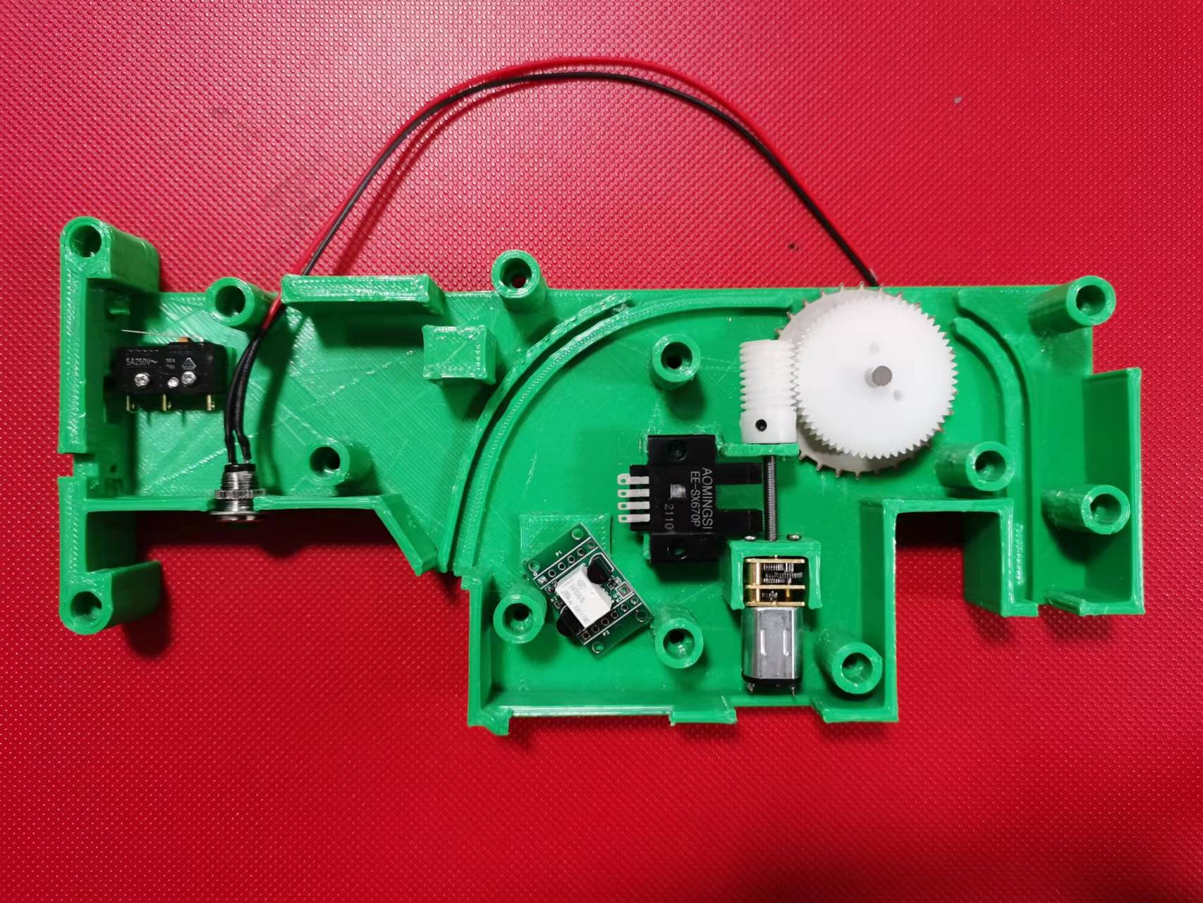
B: With the new code of the 0816 Feida controller, you can directly drive the 0775 Feida 0775 Feida circuit board without any chips. There are only three resistors, one electromagnetic relay and two 8050 transistors.
C: The noise of POM turbine is much lower than that of copper turbine.
D: 3D printing does not need to be very accurate. A layer thickness of 0.3 is enough.
E: The tape winding structure is completely COPY 0816. I don't know what the reason is. It may be that the N20 motor is not strong enough to wind the tape in time.
The cost of the whole set of materials should be about 10 dollars. This low cost conforms to the purpose of the open source project. You only need to spend time and electricity to print the shell. So I think it is better not to design the shell as PCB or metal, because that will greatly increase the cost. If you find any mistakes in this design, please let me know.
bing luo
Nov 16, 2022, 10:20:39 AM11/16/22
to OpenPnP
F: I use 1mm thick stainless steel gear because of its high strength and low cost, because I can use a laser cutting machine.
D: At present, I use a 60 rpm N20 motor, which means that the feeder can move forward 2mm or 4mm per second at most. I have tried the motor with a speed of 100 rpm. I think the power is not strong enough, but this can be solved by replacing with N30 motor.
D: At present, I use a 60 rpm N20 motor, which means that the feeder can move forward 2mm or 4mm per second at most. I have tried the motor with a speed of 100 rpm. I think the power is not strong enough, but this can be solved by replacing with N30 motor.
bing luo
Nov 16, 2022, 10:25:51 AM11/16/22
to OpenPnP
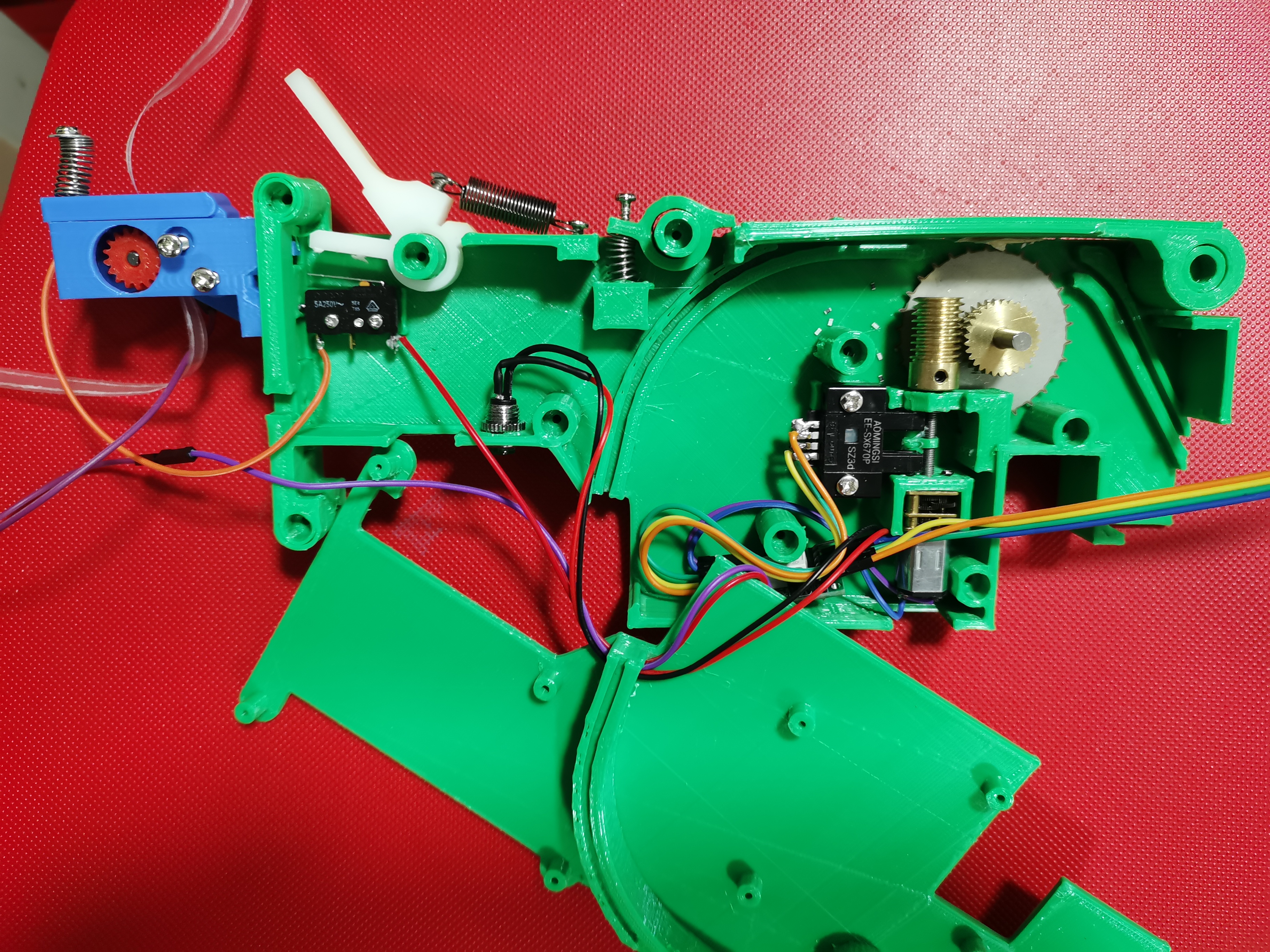 1: 30 copper turbine, a little noisy
 bing luo
Nov 16, 2022, 10:38:45 AM11/16/22
to OpenPnP
Paul Gallagher
Nov 16, 2022, 8:47:09 PM11/16/22
to OpenPnP
I am using a 12mm x 30mm long coreless motor with a planetary gear, for a commercially designed product. It drives a lead screw. It can generate up to 10kg of force at 20mm/ second. So a triple push, 12mm would be less than 0.5 seconds. Cost is a definitely more than the brass spur gear motor, but not terrible. My experience with those cheap brass gearboxes is not good. They will have short life, low power and very easy to damage. Only suitable for toys.
tianl...@gmail.com
Nov 16, 2022, 9:53:45 PM11/16/22
to Paul Gallagher, OpenPnP
It's not difficult to use any material, gear or motor. If you don't have money, you can use 3D printing. If you have money, you can use CNC. All the electric feeder made by people are using SCM, raster gear and complex programs to control the gear rotation by 2mm and 4mm . The cost is high and the difficulty is high. When I use the relay to achieve accurate rotation, the cost becomes very low.
---Original---
From: "Paul Gallagher"<pdgall...@gmail.com>
Date: Thu, Nov 17, 2022 09:47 AM
To: "OpenPnP"<ope...@googlegroups.com>;
Subject: [OpenPnP] Re: A low-cost and high-precision feeder is about to be completed
--
You received this message because you are subscribed to the Google Groups "OpenPnP" group.
To unsubscribe from this group and stop receiving emails from it, send an email to openpnp+u...@googlegroups.com.
To view this discussion on the web visit https://groups.google.com/d/msgid/openpnp/b02fd90d-5563-48df-a48d-06ebca960f4fn%40googlegroups.com.
bing luo
Nov 17, 2022, 12:58:39 AM11/17/22
to OpenPnP
Please give me your email and I will send
the drawings to you . Now the drawings are not perfect enough and can not be shared to Gihub.
Paul Gallagher
Nov 17, 2022, 2:56:25 AM11/17/22
to ope...@googlegroups.com
That would be great. Save me the trouble of starting from zero. I did look at your design by the pictures, and if you don't mind I got a couple of suggestions:
1. You really need a thrust bearing on the worm shaft. Just cheapest Chinese grade are good enough. Most of the motor torque is being lost to friction. And if possible, the gear motor should be floating to prevent any axial force on the gears. That also wastes all the torque
2. The worm gear should be small as possible diameter to reduce friction.
2. The worm gear should be small as possible diameter to reduce friction.
If you do those 2 things, you can probably at least 2x or 4X your speed. The gear motor should have plenty of power to push the tape.
As for the optical sensor. If you want to take this to the next level, use a pair of 49E Hall sensors with a ring magnet somewhere on the shaft. That way you can have full 360 degree position feedback. Of course that requires a microprocessor, but I think a cheap microprocessor and the hall sensors is roughly the same cost as the optical sensor.
--
You received this message because you are subscribed to the Google Groups "OpenPnP" group.
To unsubscribe from this group and stop receiving emails from it, send an email to openpnp+u...@googlegroups.com.
To view this discussion on the web visit https://groups.google.com/d/msgid/openpnp/e4763eff-63dc-4ef9-b6a1-80f437a58099n%40googlegroups.com.
bing luo
Nov 17, 2022, 3:08:26 AM11/17/22
to OpenPnP
Yes, the bearing can be installed on the worm,but the use of microprocessors and Hall sensors is not only expensive, but also very complex. Few people can write the program well. This is not my purpose of designing this feeder . If so, I will directly use Yamaha's pneumatic feeder.

Ravi Ganesh
Nov 17, 2022, 11:39:23 AM11/17/22
to OpenPnP
Have you thought of adding a magnetic sensor such as
RedRock TMR Switch Sensor - Coto Technology | DigiKey.
This is to sense the pick and the tape should advance automatically post pick. This way all the wires can be removed.
The Drag feeder is really cheap, but consumes more time per feed.
Automatic sensing will have the best features of the Drag feeder and a powered feeder.
I really love to work on this idea, but I don't have such fast feed requirements and hence no motivation....
This idea is just a compliment to the good work that you are doing.
bing luo
Nov 17, 2022, 12:24:08 PM11/17/22
to OpenPnP
One feeder needs to install one sensor, and 20 feeders need to install 20 sensors. This cost is much higher than that of a MEGA2560 controller worth 30 dollars. One MEGA2560 can control 24 feeders.
In addition, you need to install a complete set of microcontrollers on each feeder to control the rotation distance of the gear, because you need to make the gear rotate 4mm, 8mm, 12mm, 16mm, 24mm It means that the turbine will rotate 1, 2, 3, 4 and 6 times.

Jon Raymond
Nov 17, 2022, 12:32:07 PM11/17/22
to OpenPnP
Are you planning on selling a kit for all that parts for this feeder? Sourcing the indexing wheel, worm and drive sprocket are what hold most people up.
bing luo
Nov 17, 2022, 9:15:55 PM11/17/22
to OpenPnP
At present, it is not 100% accurate. I am looking for the reason. If there is no problem, I will sell the kit at a price of 13 dollars.
Reply all
Reply to author
Forward
0 new messages