Secondary Z fiducial nozzle misalignment

Litterio Andrea Guainella


mark maker
Hi LAG,
I read your post a few times, but I do not understand what the actual problem is?
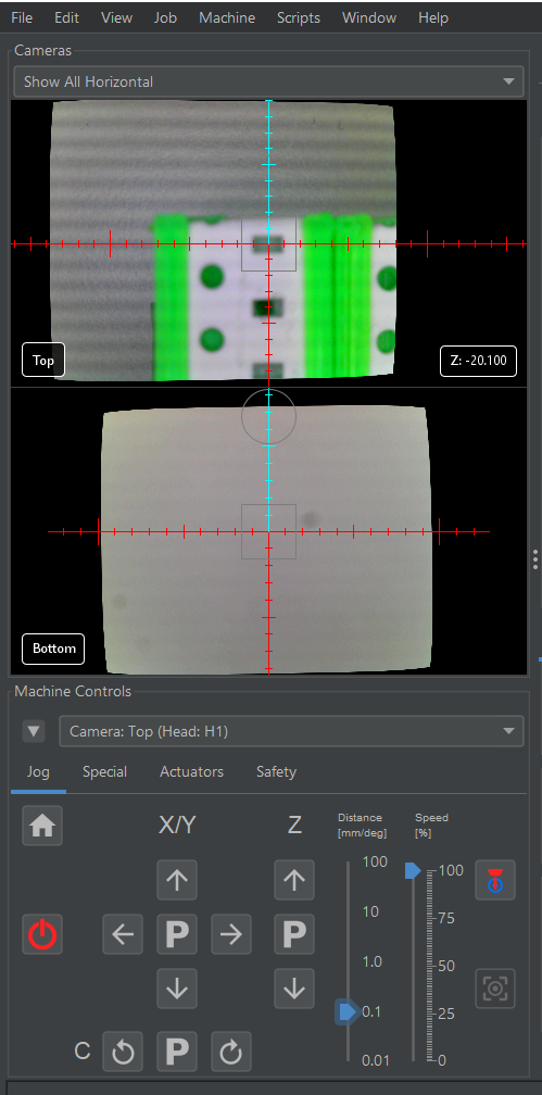
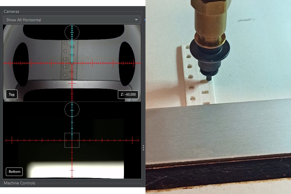
The images look good, the virtual Z is indicated on the camera
view as -20.1mm, which means your PCB would be at ~-42mm which
sounds about right for a Liteplacer, that I guess this is. The
ticks on the cross-hairs look good, they seem to align 4mm with
the sprocket hole pitch.
So everything seems to work alright. What is the problem?
Obviously the image is a bit blurred but that should not bother computer vision. If not, try this alternative pipeline here, assuming you use the ReferenceStripFeeder:
https://github.com/openpnp/openpnp/wiki/DetectCircularSymmetry#referencestripfeeder
_Mark
--
You received this message because you are subscribed to the Google Groups "OpenPnP" group.
To unsubscribe from this group and stop receiving emails from it, send an email to openpnp+u...@googlegroups.com.
To view this discussion on the web visit https://groups.google.com/d/msgid/openpnp/db4473e6-0704-4951-ad14-f21b02d654ecn%40googlegroups.com.
Litterio Andrea Guainella
As you can see from 2nd image the nozzle not centered in part when I simulate pickup.
The horizonal black band was caused from led bar near table (the ceiling is lower than normal and this affects the camera vision).
Now I haven't problem with cvpipeline so I just used default but thank you for your suggest.
mark maker
Ah, now I understand. So the problem might either be a tilt in
the Nozzle Z axis or the camera Z axis (view axis).
But tilt in the camera is unlikely, as it happens with both
Advanced Camera Calibration and without. Please confirm
that you performed the camera calibration with the newest
version, i.e. after the
disable-tangential-distortion-correction="true"was established.
Right? (it is not sufficient to update, you need to perform the
calibration again, after updating OpenPnP).
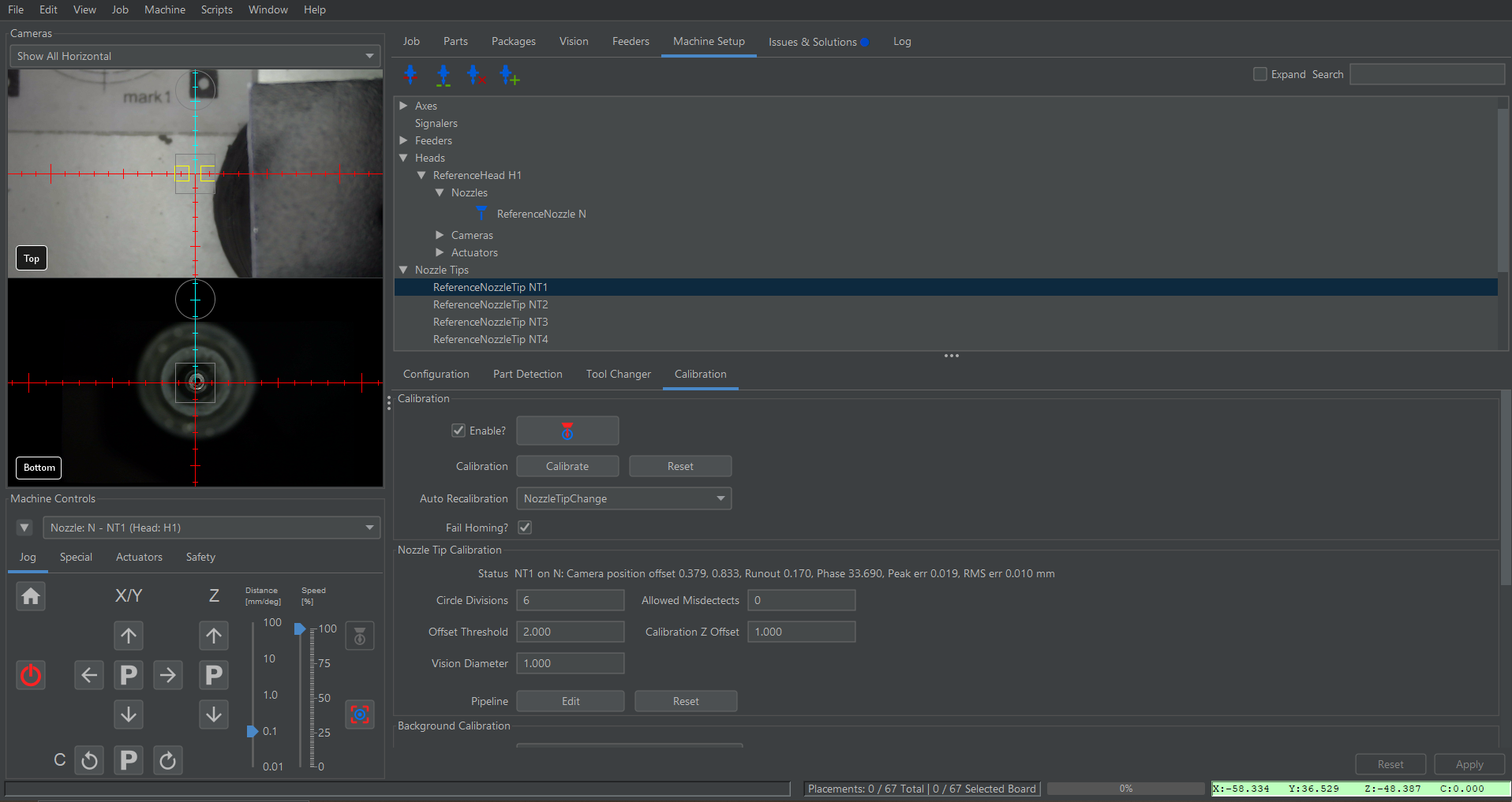
Then just to be sure, let's confirm it is not just a problem of the feeder's specific programming:
Center the camera on the feeder (like the corner of a pocket or something you can judge), then use this button:
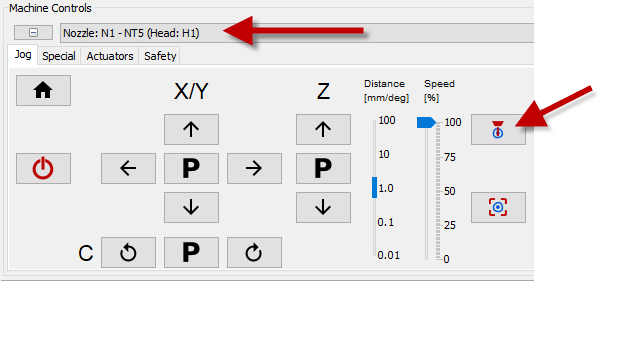
Does it show the same offset?
If yes, then tilt in your Nozzle is almost sure.
I don't think you can adequately measure this with a bubble
level. In fact I don't know an easy way.
@Others, how do you measure if the Z
axis is not tilted?
20mm difference in Z is a lot. I can only repeat: try to use
the same Z as for the PCB.
Why do your strip holder need to be 20mm high? This takes a lot
of 3D printing time!
Have a look at BlindsFeeder for contrast. They're super fast to print, add minimal Z height (only as much as the part height) and can (optionally) cover the parts, so they don't fall out, are faster to pick (vision only once per job), can optional have OCR/Barcode/QR code.

https://github.com/openpnp/openpnp/wiki/BlindsFeeder
And despite the Liteplacer being ready, you can't use Contact
Probing, because the tape strips are only suspended on the
sides, and would be poked-through if probed, or parts would surely
topple out from vibrations.
https://github.com/openpnp/openpnp/wiki/Contact-Probing-Nozzle

I know, you already printed the feeders... but maybe you should still reconsider 😉
_Mark
To view this discussion on the web visit https://groups.google.com/d/msgid/openpnp/b87cb17d-d80b-4c9d-9f28-8dc8ba85c6a2n%40googlegroups.com.
Litterio Andrea Guainella


tonyl...@gmail.com
mark maker
tony> If we did the confetti trick at both the primary and secondary fiducial height we could measure it😉
After Advanced Camera Calibration, and assuming it did detect the camera view axis tilt accurately, yes! It would be easy to add. I'll keep that in mind.
LAG> For avoid any problem I deleted .openpnp2 folder before installation.
You really do not need to do that each time, unless you
completely wrecked the config. Usually, just reopening all the
subsequent Issues & Solutions items is sufficient.
For most things, Issues & Solutions is permanently
monitoring your settings, i.e. the suggestions are not
"one-shot". If settings do not match according to its logic, it
will alert you, again. This is true for maybe 80% of the
settings it can propose.
For the rest, there are some (like the calibration steps) that
need to be re-opened explicitly, if the machine has
changed, because it cannot detect that. Very few solutions are
"one-shot": Issues & Solutions will only propose them if they
are empty/missing. This is for machine specific stuff, where
I&S can only guess. Like some machine specific G-code
commands. If in doubt just delete these and a new proposal will
come.
So it is only these few that you need to keep in mind.
_Mark
To view this discussion on the web visit https://groups.google.com/d/msgid/openpnp/f159d11f-88e5-48fe-9da4-0290172c862dn%40googlegroups.com.
tonyl...@gmail.com
mark maker
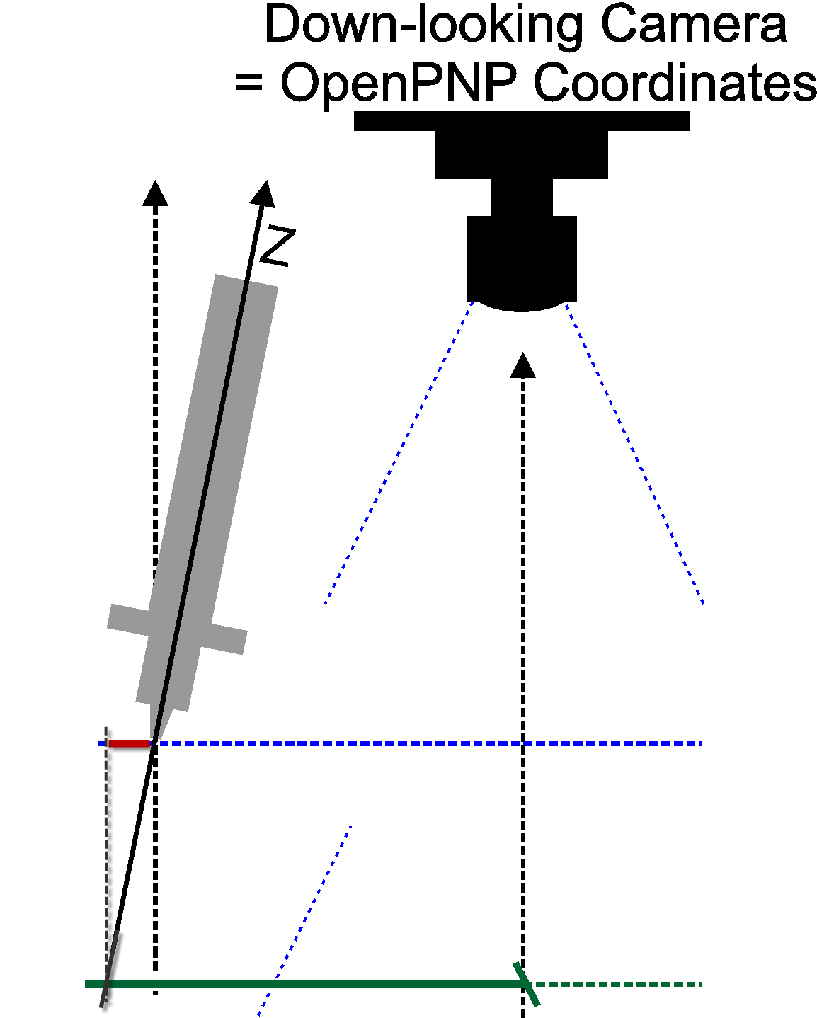
I don't understand. It is true that the down-looking
camera tilt and the nozzle tilt cannot be distinguished from two Z
level confetti calibrations, right?
For example, these two (exaggerated) constellations will exhibit the same apparent delta:
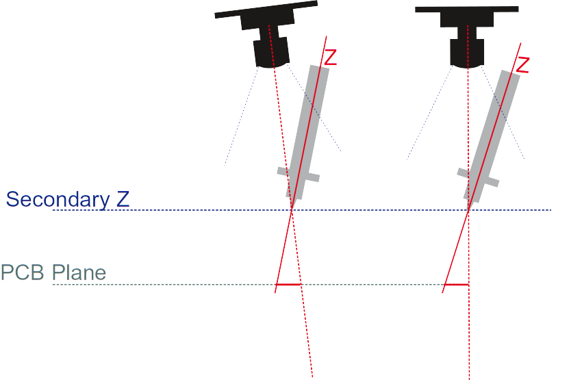
Or do you suggest to first just determine the overall tilt and
then only adjust (as a computation) the nozzle tilt for
the camera tilt, once the Advanced Calibration was done? That
would be possible, I guess.
_Mark
To view this discussion on the web visit https://groups.google.com/d/msgid/openpnp/213325b1-dd48-4b7d-8a04-f5d82b08f88cn%40googlegroups.com.

bert shivaan
To view this discussion on the web visit https://groups.google.com/d/msgid/openpnp/fec660c3-8602-cbb2-a1ce-1a671d82471c%40makr.zone.
tonyl...@gmail.com
bert shivaan
To view this discussion on the web visit https://groups.google.com/d/msgid/openpnp/e33ce1c8-a8b2-4361-9170-3b272df21ba8n%40googlegroups.com.
mark maker
@Tony> it doesn't really matter whether one or the other or both are tilted
Yes this is true (but see cncmachineguy's valid point, later).
You kind-of make the camera view axis (with whatever tilt it has)
the "reference", all the machine's nozzles have to adhere to it.
But you have to adjust all these nozzle specific tilts, once you perform the Advanced Camera Calibration, as it's tilt compensation selects another "pixel ray" as the camera view axis. I.e. you get this:
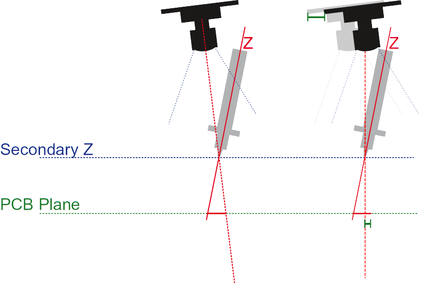
Or are you saying we should abolish its tilt compensation?
@cncmachineguy> Could the nozzle tilt not be found by simply parking the nozzle over the bottom camera, take a snap shot at z fully retracted, then extend z fully and take another snap shot.
Same problem. Camera tilt is not distinguishable from
nozzle tilt.
But admittedly, it would be easier to implement (compared to the
confetti trick).
@cncmachineguy> Would it fail if the spot we are trying to hit is calculated position instead of captured by vision?
You have a valid point there. Whenever OpenPnP would make a move
based on taking X, Y from another Z and then perpendicularly
extending from this to another wanted location, this will incur
the camera tilt error.
In case of a (tall) BlindsFeeder, where it takes the fiducial X/Y
from down at the table, but then wants to push the cover
edge up at part height, based on "blind" geometrical
knowledge of how the feeder is made, this will falsely add the
camera tilt. In case of the BlindsFeeder this is not a
problem, because it knows it has to cope with deft errors from 3D
printing and adds a 2mm tolerance when approaching, and gives
you edge calibration with a vision feed-back loop, i.e. it
does not do it "blindly" in the end.
But for other truly "blind" geometric moves with tall structures,
this might become a problem. I'm thinking about nozzle tip
changers etc.. So I still think it would be better to simply first
calibrate camera tilt using Advance Camera Calibration (that I now
find trustworthy after the "tangential" fix) , and then
nozzle tilt to that reference. So we get true motion
geometry (or as "true" as can be achieved).
Backlash...
Note, as @Tony already mentioned, this needs special treatment
for Backlash Compensation in X/Y. It effectively has to take the final
location into account when calculating the X/Y move at Safe Z,
i.e. it need to already include the nozzle tilt compensation up
there, so any backlash counter-move can be done "up in the air"
where it is harmless (not down when pressing a part into solder
paste). Afterwards, only the Z axis will go down, no tilt
compensation along the way.
Folding the backlash counter-move into the downwards-move (saving
the extra time) would be the "luxury" solution. But because these
two concerns are currently (very) separated, it will probably not
be done anytime soon.
_Mark
To view this discussion on the web visit https://groups.google.com/d/msgid/openpnp/CA%2BKNHNxwynuS2Z%2BqV0wH%3DG7XBdmehw8gqTjyHG56vJ9mieki5w%40mail.gmail.com.
tonyl...@gmail.com
mark maker
> That can't be any worse.
True.
To view this discussion on the web visit https://groups.google.com/d/msgid/openpnp/fa576c5c-f8ae-42cf-be55-ba26b10cb2ben%40googlegroups.com.
tonyl...@gmail.com
Litterio Andrea Guainella
tonyl...@gmail.com
Litterio Andrea Guainella
mark maker
> i am having several problems to print it because I've
never printed PETG
Do you use adhesive spray? And enough of it? Once I did that: all problems gone.
_Mark
To view this discussion on the web visit https://groups.google.com/d/msgid/openpnp/0add3af6-21a0-4f01-8bee-d41765cb1892n%40googlegroups.com.
mark maker
Just to be clear I meant that special 3D printing spray, not "adhesive" spray.
That's the one I'm using (that's just the first one I tried and
it worked well, others may too):
_Mark
To view this discussion on the web visit https://groups.google.com/d/msgid/openpnp/481849c1-ebe4-f255-c586-63d885f54aed%40makr.zone.
Litterio Andrea Guainella
I am trying with Splend'or (hair spray ~ cheapest way) waiting for 3dlac to arrive.
When finish I will post some image for details
Litterio Andrea Guainella
Litterio Andrea Guainella
Litterio Andrea Guainella
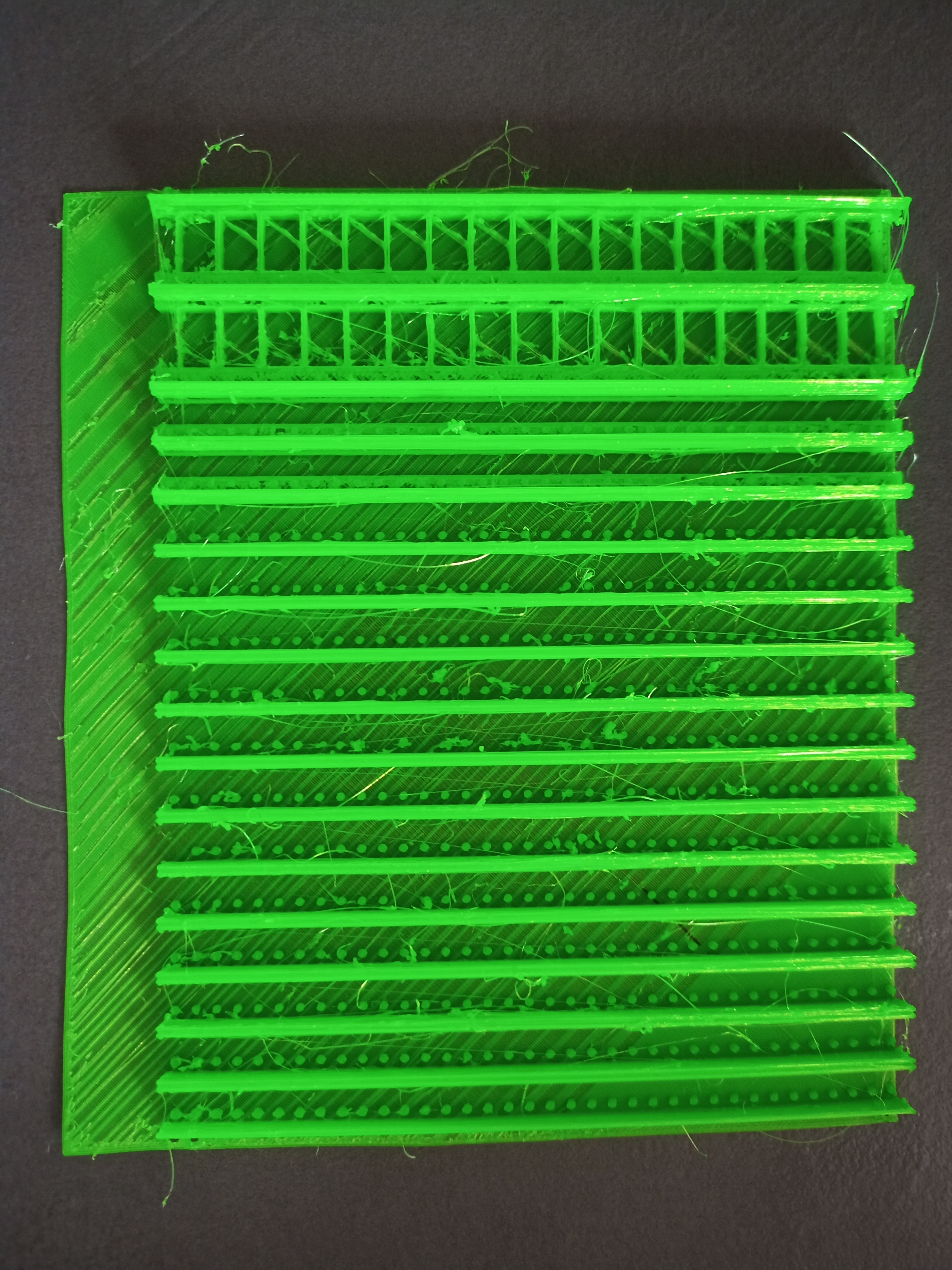
attach 1
Litterio Andrea Guainella
Litterio Andrea Guainella
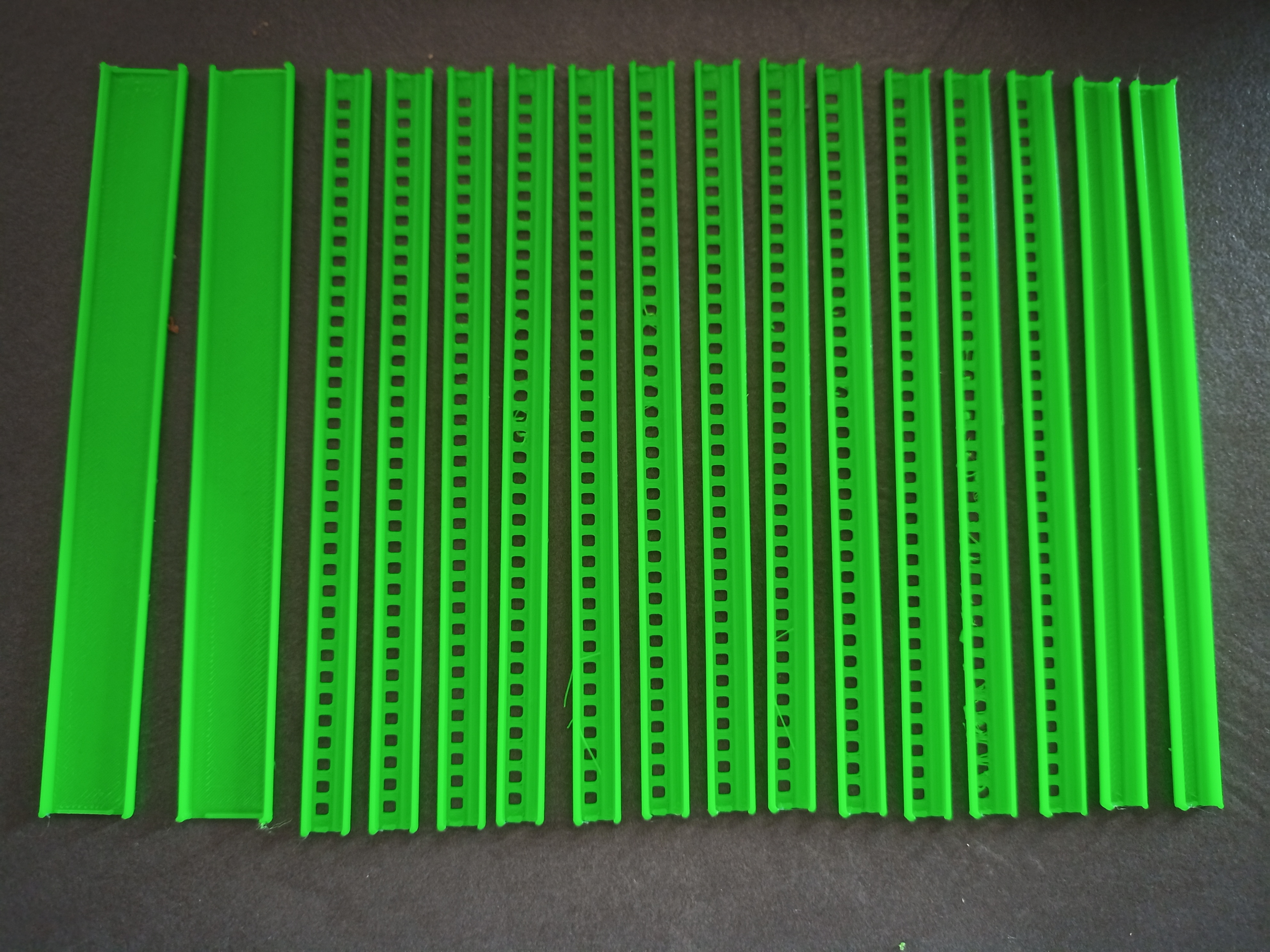
Litterio Andrea Guainella
mark maker
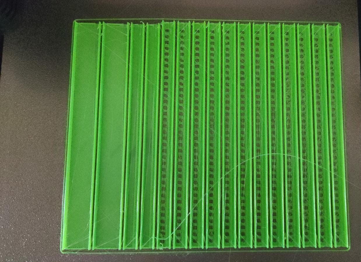
Hi Litterio,
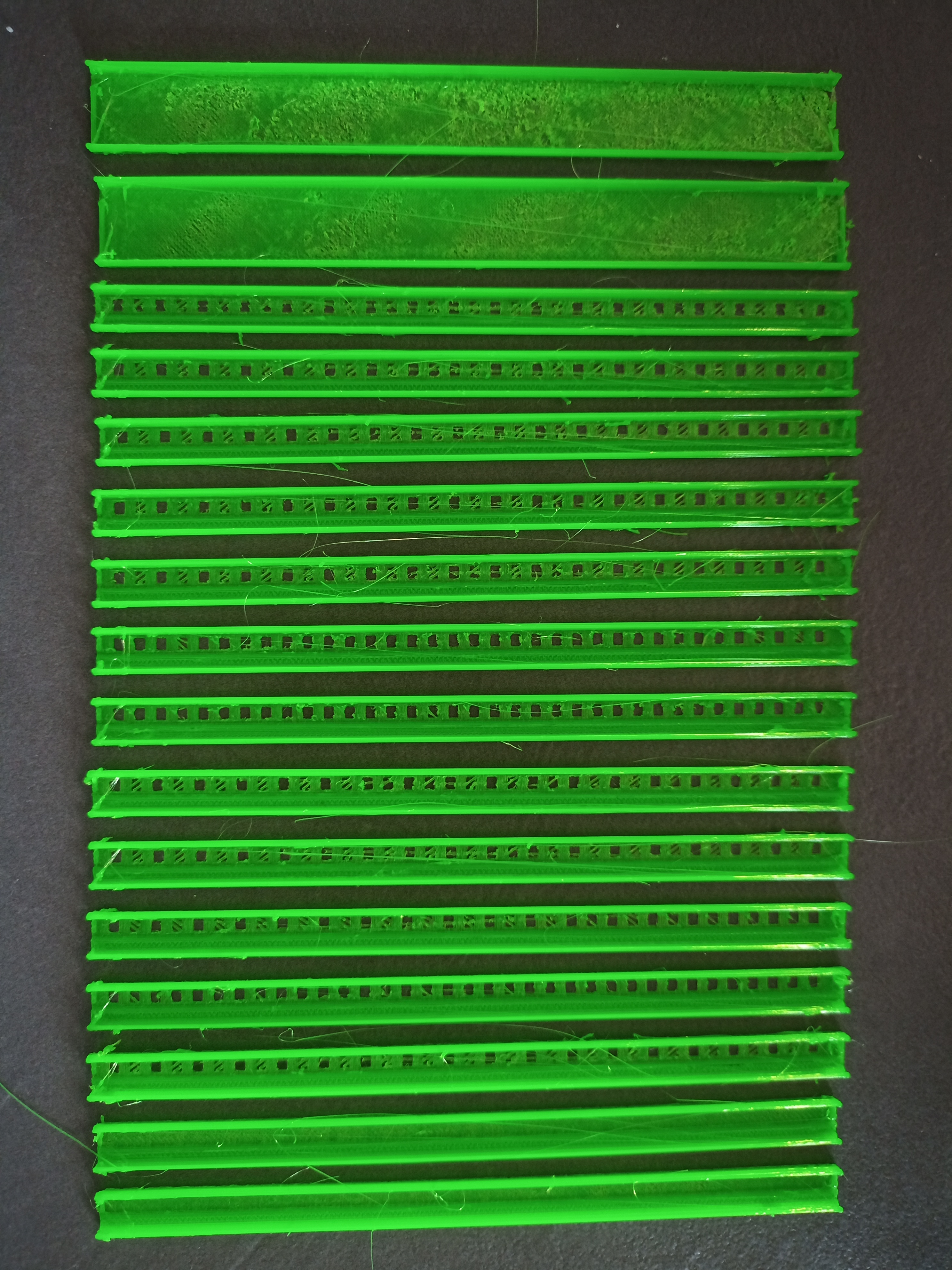
these prints really look scary.
Although I've made quite elaborate stuff (see also the Push-Pull
Feeder), I don't consider myself a 3D printing expert,
mainly because my Prusa printer just worked (at least once I found
the spray is needed).
Sometimes I had stringing when the temperatures were not right,
but that looked more like fine "spider webs", not the thick "crazy
spaghetti" you get.
Are you sure you got the temperatures right and your printer can do these high temps without an encasing?
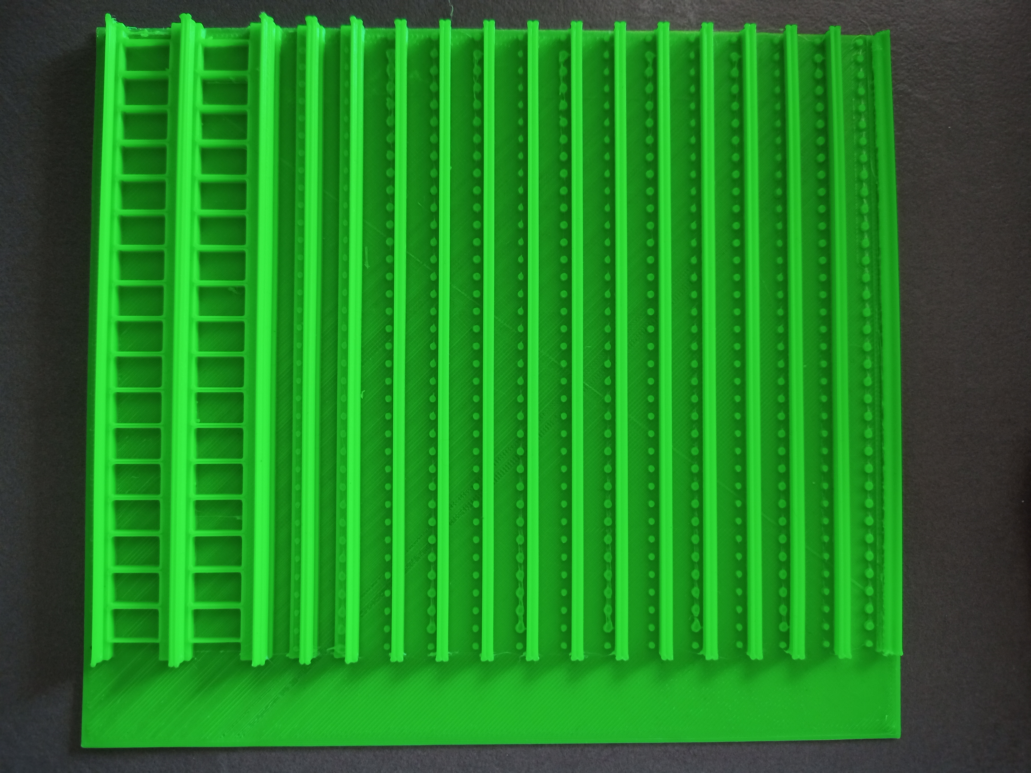
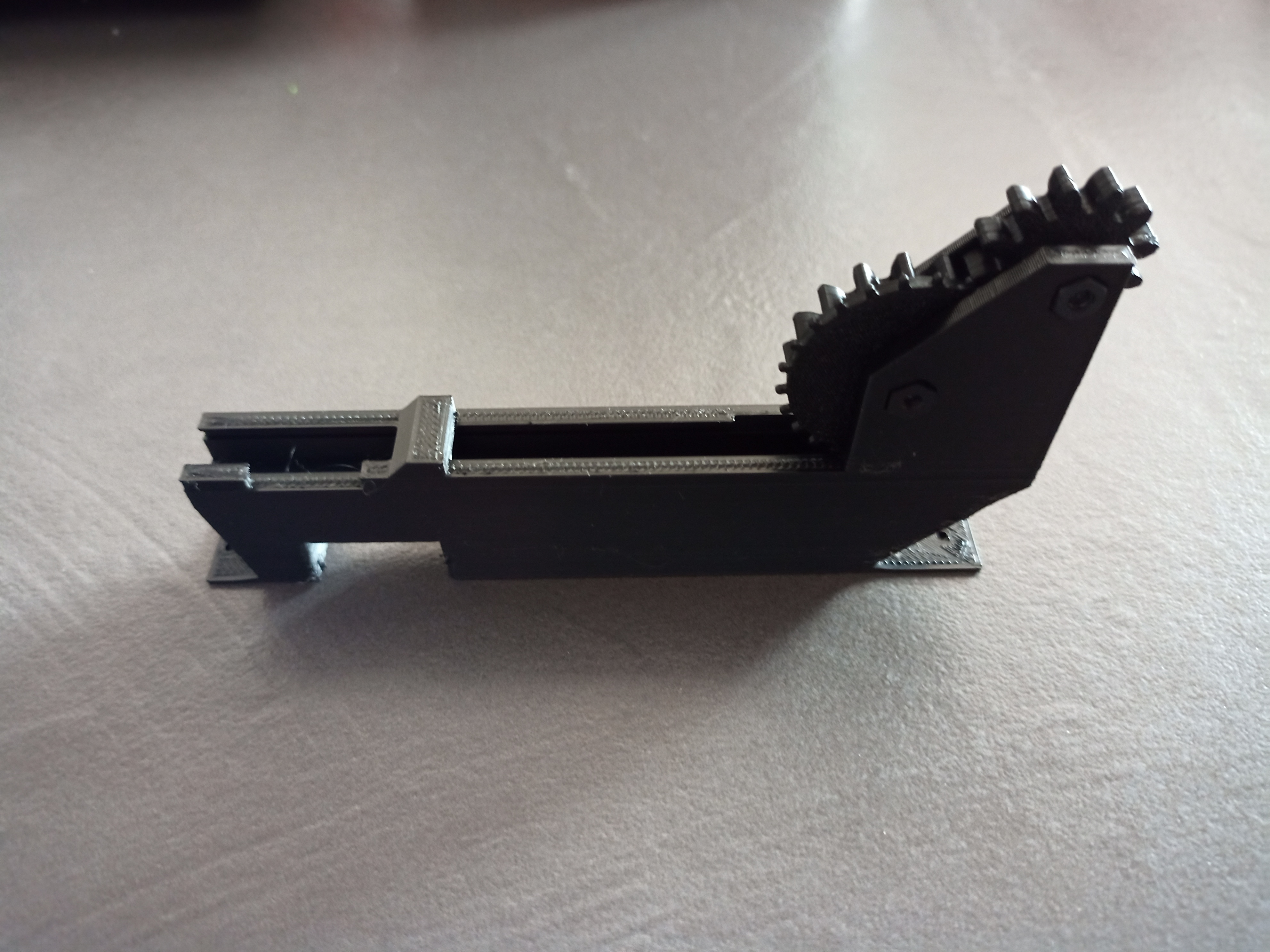
That last gray model (different feeder): is that PETG too?
I'm just asking, because PETG is a much tougher, much more
elastic and also smoother material than PLA (less friction between
moving parts), and according to the link you sent for the other
feeder, this one is printed in PETG too, specifically for
friction.
So maybe you should still invest more in trying to solve the PETG
printing issue.
I assume you know the BlindsFeeder is a completely different use
case, than the one you are now printing. BlindsFeeder can only be
used for very small runs, where you buy a few dozen of each part.
On the other hand, it can use every last one of these parts on
even very short cut strips (no waste), which might be important
for expensive parts. It is also very compact, you can put many of
them on your whole table.
The other feeder is completely different, it only makes sense when you buy whole reels or at least very long cut strips, and you don't mind wasting some of them for the needed cover tape leads etc. Plus it consumes much more space, and works only on the edge of the machine.
_Mark
--
You received this message because you are subscribed to the Google Groups "OpenPnP" group.
To unsubscribe from this group and stop receiving emails from it, send an email to openpnp+u...@googlegroups.com.
To view this discussion on the web visit https://groups.google.com/d/msgid/openpnp/1f931b15-56ba-4b82-8129-a4aefd2cab5cn%40googlegroups.com.
Litterio Andrea Guainella

Vinay Dand
1) If possible dry out the PETG spool, many time moisture ingresses in the filament and causes this.
Best Regards,
Litterio Andrea Guainella
mark maker
> I will try as you said but I don't have an dry machine for filament. I'll have to buy one.
Instead of buying ever more things to try and make the printer work, you might consider buying a new printer. 😇
Obviously, I strongly recommend the Prusa, that thing just
works!
At €700 (kit) it has its price, I know, but it is a long-term
good investment, I already upgraded mine once, you always get the
newest model for very little extra money. I bought a second
printer and can tell the upgraded one and the new one are exactly
the same in all relevant aspects.
@Vinay, as to drying out the PETG, are you sure that can be an
explanation for such phenomenons? Wouldn't water rather show up as
bubbly surface?(again, I'm no expert).

To view this discussion on the web visit https://groups.google.com/d/msgid/openpnp/87b2311e-fed7-4824-91fc-df5908216c0fn%40googlegroups.com.
Vinay Dand
You received this message because you are subscribed to a topic in the Google Groups "OpenPnP" group.
To unsubscribe from this topic, visit https://groups.google.com/d/topic/openpnp/bzLiD6QZIqY/unsubscribe.
To unsubscribe from this group and all its topics, send an email to openpnp+u...@googlegroups.com.
To view this discussion on the web visit https://groups.google.com/d/msgid/openpnp/8cbc2dc1-3830-91f9-5620-d3003fe01510%40makr.zone.
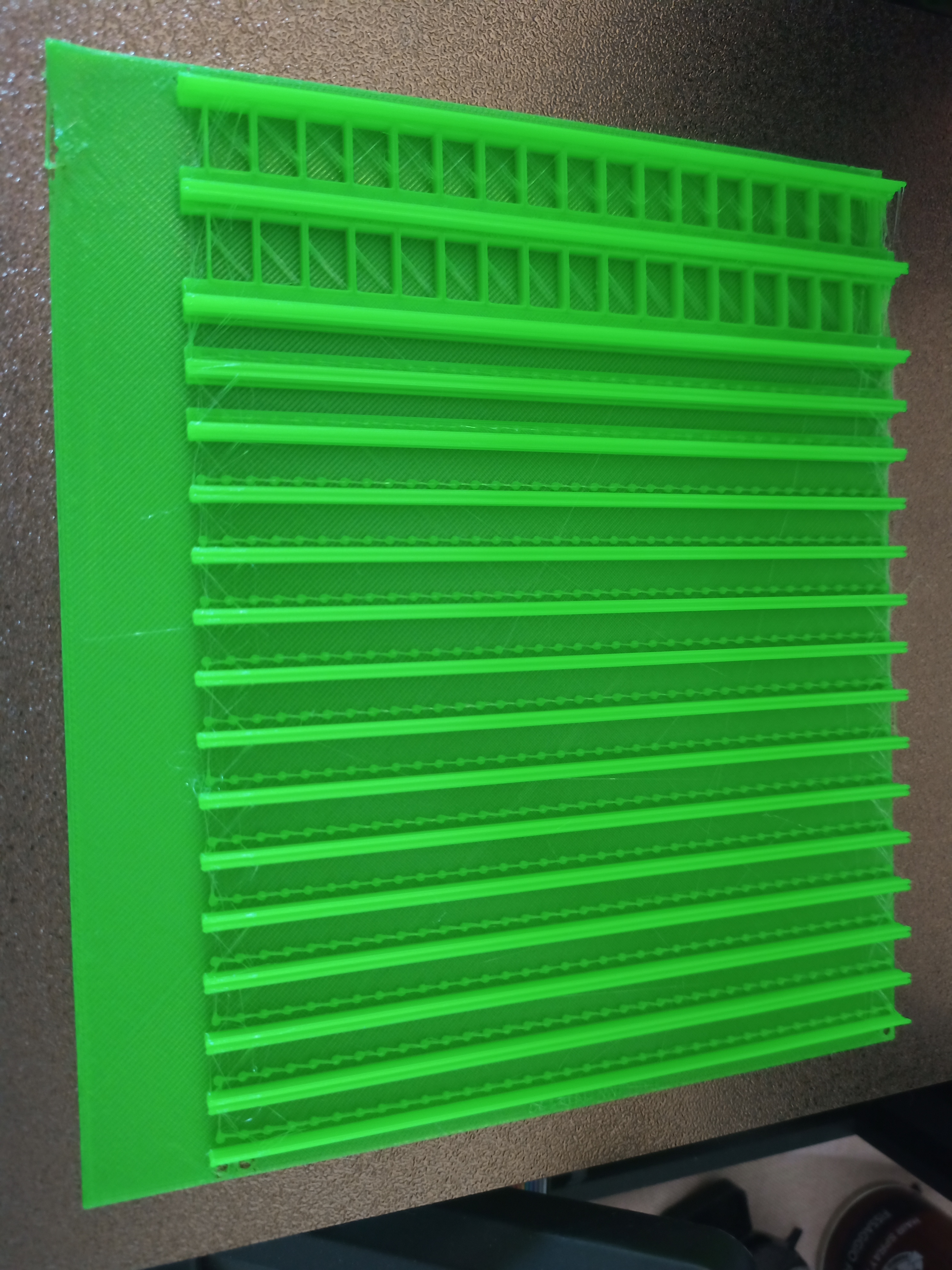
Litterio Andrea Guainella
I'll try to print later 2nd face (this is only cover).
mark maker
Getting better but I guess not yet good enough.
Are there no 3D printing gurus on the list who could help?
_Mark
To view this discussion on the web visit https://groups.google.com/d/msgid/openpnp/e1eb41db-00f8-46de-8adc-7a6edddb6744n%40googlegroups.com.
Litterio Andrea Guainella
Litterio Andrea Guainella
bert shivaan
--
You received this message because you are subscribed to the Google Groups "OpenPnP" group.
To unsubscribe from this group and stop receiving emails from it, send an email to openpnp+u...@googlegroups.com.
To view this discussion on the web visit https://groups.google.com/d/msgid/openpnp/fd944751-3786-410a-8ef7-52d11b15a4een%40googlegroups.com.
Litterio Andrea Guainella
I was try to search in group but I find nothing.
bert shivaan
To view this discussion on the web visit https://groups.google.com/d/msgid/openpnp/1fa044c3-476e-4605-86ed-1a497d4a5ec6n%40googlegroups.com.
Litterio Andrea Guainella
mark maker
Hi LAG,
Try this:
- I am assuming you re using Issues & Solutions to
use the Advanced Camera Calibration. Disable it on the camera
and then press Find Issues & Solutions to get it
proposed again.
- exit OpenPnP
- edit machine.xml
- double-check that you find these settings in both cameras:
disable-tilt-correction="false" disable-distortion-correction="false" disable-tangential-distortion-correction="true"
- search for up-looking-secondary-offset-Z-mm=
- change the value (default 2mm) to something larger, where the
nozzle tip is still not too blurred and the nozzle tip circular
feature still roughly the same size (so it gets detected).
- Maybe a larger Z difference will improve the tilt compensation
accuracy. Please report back if possible.
_Mark
To view this discussion on the web visit https://groups.google.com/d/msgid/openpnp/a55367fd-efd8-4ad6-8aa6-1e0f05c98045n%40googlegroups.com.
Litterio Andrea Guainella
thank you for your suggest. Now I have just dissassembled both camera so I can't try this procedure.
I will try this when finish mount new ELP cameras.
tonyl...@gmail.com
Litterio Andrea Guainella
Litterio Andrea Guainella
tonyl...@gmail.com
Litterio Andrea Guainella
Litterio Andrea Guainella
mark maker
> Mark - your points 5 through 7 only really apply to
up-looking cameras - correct?
Correct.
> If I understand the OP's problem, it is with the down-looking camera and/or the nozzle's Z-axis.
Oh, I must have misunderstood. I was aware that the original
problem is a difference in nozzle offsets on the two different Z
levels. Which might hint at either nozzle Z tilt or (wrongly
calibrated) top camera tilt. But now I assumed he was talking
about seeing the nozzle displace in X/Y when looking up with the
bottom camera and jogging in Z. After rereading his post, I see
that I'm probably mistaken.
So yes, my steps 5 - 7 do apply to the bottom camera
and using it to check for nozzle tilt. i.e. seeing
whether the nozzle displaces in X/Y when moving in Z.
_Mark
To view this discussion on the web visit https://groups.google.com/d/msgid/openpnp/7a17be1c-db26-4495-b88e-6c9d73cda476n%40googlegroups.com.
Litterio Andrea Guainella
tonyl...@gmail.com
Litterio Andrea Guainella
Detected Backlash: 0.173mm
Selected Method: OneSidedPositioning
Sneak-up Distance: 0.000mm
Speed Factor: 0.25
Applicable Resolution: 0.0125 mm
Detected Backlash: 0.106mm
Selected Method: DirectionalSneakUp
Sneak-up Distance: 0.226mm
Speed Factor: 0.25
Applicable Resolution: 0.0124 mm
mark maker
Hi LAG,
I hope you keep your spirit up! 💪 😁 👍
I think there are many things that can make a Liteplacer not
work. The construction is really very simple and also outdated.
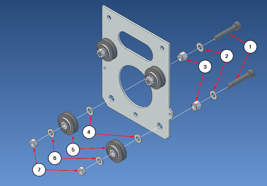
For instance all the gantries are tensioned with these eccentric
spacers (3). If you make them too tight the gantry will not
slide well, which could be one of many explanations that your
steppers stall. But if you make them too lose, the gantry will
wobble and vibrate, which might in turn stall the stepper when you
go very fast, the vibration creating so much friction.
https://liteplacer.com/the-machine/assembly-instructions/gantry-back-plate-step-2-lower-v-wheels/
To view this discussion on the web visit https://groups.google.com/d/msgid/openpnp/e4a2728e-b0e5-46b7-8adc-8f697bf044a3n%40googlegroups.com.