Motion blending

Jarosław Karwik

Mark
Hi Jarosław,
I believe we discussed it before ...
- For most controllers that are just constant acceleration
controllers (2nd order), OpenPnP can create motion
blending, using interpolation, also adding 3rd-order control
(jerk limit). This generates a very high volume of short motion
segments. No known controller is so far fast enough (in
communication and planning) to make it worthwhile for practical
PnP moves.
- For the few controllers that use simplified S-curves (not
7-segment), interpolation is not possible as they do not support
acceleration != 0 in junctions.
- For advanced controllers that are true 7-segment S-curve
controllers (true 3rd order), there is currently no
solution yet, the assumtion was that such an advanced controller
could perhaps also implement it itself. Remember, we
exchanged code previously.
Note: I have since become wiser too, and would today use a
different approach:
- Previously, I've used uncoordinated motion for the
smoothing, i.e. the motion planner can allow some of the
trajectories to deviate from the straight line between points,
allowing for the curvature that makes the trajectory smooth. In
our PnP application, we allow uncoordinated motion inside the
Safe Z zone, it results in what I call "Z overshoot". That
solution is currently implemented in OpenPnP.
- Now, I would rather use true motion blending, which
overlaps/blends the relative motion of two segments for
a specific duration. I think that's also what the NIST standard
for G-code talks about. Unlike the previous solution, the
trajectory no longer goes through the corner points, but only
approaches them, with a tolerance for cutting the corner. This
means that for such a controller (including LinuxCNC with G64)
the OpenPnP code would have to be extended . It means that the
correct Safe Z overshoot must be computed and the corners
"stretched" up accordingly, dependent on the X/Y distance of the
move (at least if you want best performance), plus the blending
tolerance (G64) would have to be set accordingly.
_Mark
--
You received this message because you are subscribed to the Google Groups "OpenPnP" group.
To unsubscribe from this group and stop receiving emails from it, send an email to openpnp+u...@googlegroups.com.
To view this discussion on the web visit https://groups.google.com/d/msgid/openpnp/082638e8-d2ef-4081-9f9d-513095ca740bn%40googlegroups.com.
Jarosław Karwik
Mark
> I know somehow safe Z - is it available in macros in Gcode driver ?
No. But such extra variables could be easily added to the
GcodeDriver (e.g.
here).
Note: it would be a Safe Z Zone, not just a single Safe
Z, because with dual nozzle machines the Safe Z Zone is in the middle
of the raw Z axis range.
> I would need to add some FIFO and delay to collect move commands sent by OpenPnp - right now the gcode moves are processes immediately
Definitely. If by "delay" you mean a grace period, that exactly
what we have done for Duet. Except for manual jogging, here
is always an M400 command that closes a motion sequence, so either
the grace period timeout or the M400 should execute the queued
motion.
_Mark
To view this discussion on the web visit https://groups.google.com/d/msgid/openpnp/31a31257-25fb-4a4c-afc0-0f4e85e7c086n%40googlegroups.com.
Jarosław Karwik
Mark
> I made some simplification of the general case - I assign half of XY travel distance for each blending. While this is not the most optimal strategy in general case, it still should cover 99.9% of real cases.
That would be counter-productive. With your method, longer X/Y
distances result in flatter curves, i.e. the corner is slower
instead of faster. Short moves are going too high in Z.
I would do it as follows (numbered for easy referencing):
- We want to save time, so it is better to think the
blending in terms of time, not distance.
- By overlapping the time to decelerate Z, and the time
to accelerate X/Y, we can (more or less) save that amount
of time per corner (the other corner is just the same in
reverse).
- If the X/Y displacement is large, then the overlap time is
determined by the time it takes to decelerate Z.
- We want to drive the nozzle up as fast as possible, this means
that ideally, we do not want to decelerate before we hit the
minimum Safe Z height (at whatever speed and acceleration we can
achieve).
-
If our head-room (Safe Z Zone) is large enough to fully
decelerate Z, we can take the full Z deceleration time as the
overlap time. The upper Z of the arc is determined by the
braking distance.
- If our head-room (Safe Z Zone) is not large enough to decelerate Z, we need to start decelerating earlier. The overlap time is then just the fraction of the deceleration time that happens above Safe Z. The upper Z of the arc is then determined by the headroom (Safe Z Zone).
- If the X/Y displacement is small, then the overlap time is no
longer determined by Z deceleration, but by half the X/Y motion
time.
- In that case we can take this half X/Y time and calculate the
Z braking distance that is achieved in this time (reverse from
still-stand). This braking distance added to Safe Z gives us the
upper Z of the arc.
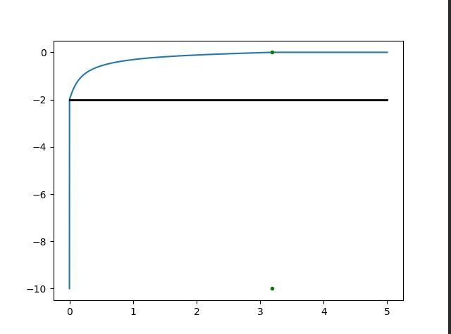
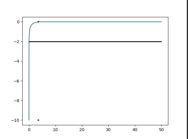
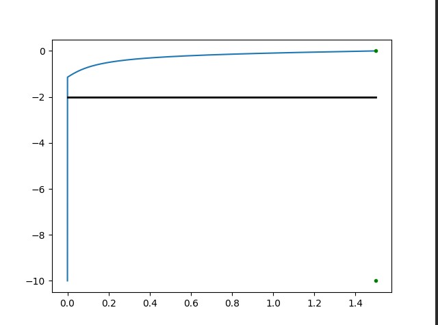
- This basically means that at some point smaller X/Y moves will
result in less and less "overshoot" into the Z headroom, the arc
becomes lower and lower. It is logical: if we just have a tiny,
tiny move in X/Y, then the fastest way to go to Safe Z and then
back is still to just go to Safe Z and not higher.
- Finally, simply start the motion of X/Y earlier by this
overlap time, and vector-add its relative displacement to
the still decelerating Z motion.
- This bleding in time gives us the shape of the arc. For large
X/Y moves it will just round the corners. For small X/Y moves
(7) it will create a true arc.
- With 2nd order motion control, the above rule set can directly be used to create the blending.
- With true 3rd order motion control, this is complicated by
jerk control, i.e. the switch from accelerating Z to
decelerating Z is not instantaneous. So computing (5) and
especially (8) is probably best done using some sort of
iteration/numerical solver. It does not have to be super
accurate, so the solver can terminate early to avoid a
computation bottleneck.
_Mark
To view this discussion on the web visit https://groups.google.com/d/msgid/openpnp/f0cee828-886a-4024-8a94-bece66e91f42n%40googlegroups.com.
Jarosław Karwik
Mark
> I guess you assume the same dynamic over Z and XY -
otherwise there would be ovals, not circles
No, I assume nothing! The dynamics of Z is just taken as it is and blended in time with the dynamics of X/Y, again as it is!
Your motion planner would have to be able to conduct the 7
segment planning of Z independently from the 7 segment
planning of X/Y. Two independent time axes!
There can be different durations of jerk segment,
acceleration segment etc. so this will by no means form a "circle"
or "ellipse". In fact, this would not even be the case if the
segments did coincide in time. Remember, a circular shape
is created by sin(t)
and cos(t) while
our displacement is a piece-wise 2nd or even a
3rd order polynomial of t.
_Mark
To view this discussion on the web visit https://groups.google.com/d/msgid/openpnp/77408859-d2f3-413a-b5e0-b68ff045ec89n%40googlegroups.com.
Jarosław Karwik
Mark
> that is why I was surprised that you mentioned circles
I said "round corners" and "true arc", not meant to imply true circularity 😉
_Mark
To view this discussion on the web visit https://groups.google.com/d/msgid/openpnp/08b69024-ee76-4da2-8c90-767761a48ffdn%40googlegroups.com.