[OpenPnp] Placement Offset..again
617 views
Skip to first unread message

manu f
Oct 13, 2021, 7:18:08 AM10/13/21
to ope...@googlegroups.com
Hello all,
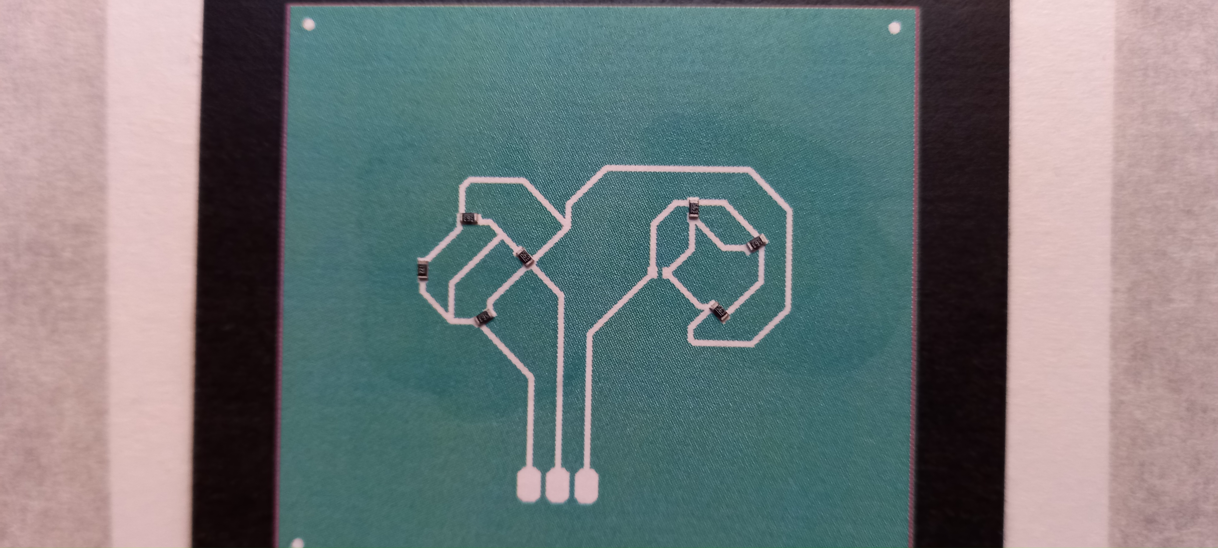
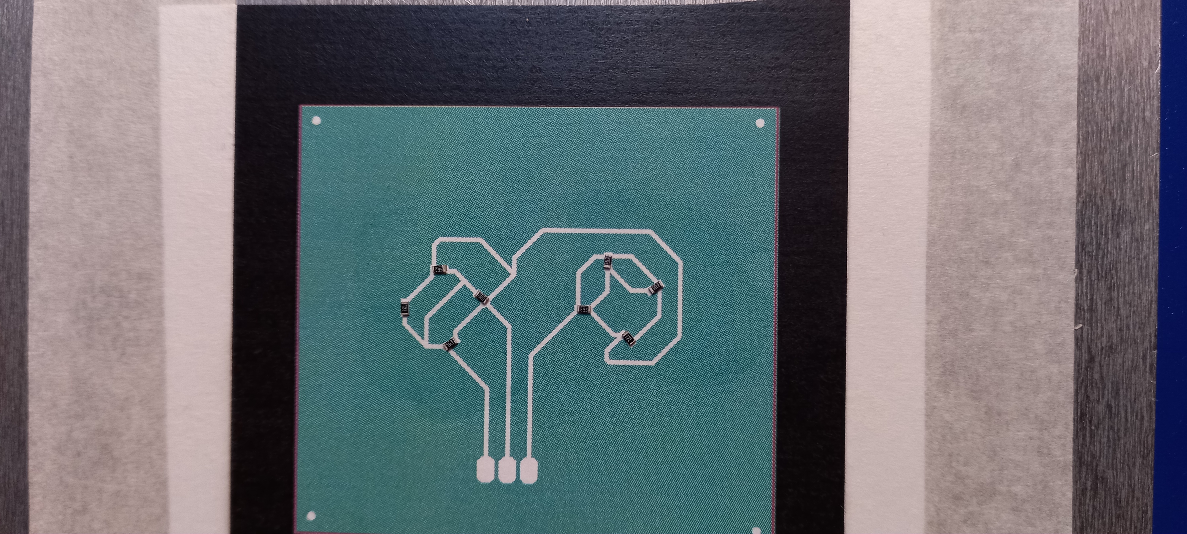
after calibrate my machine I started to place component and I got offset on placement :
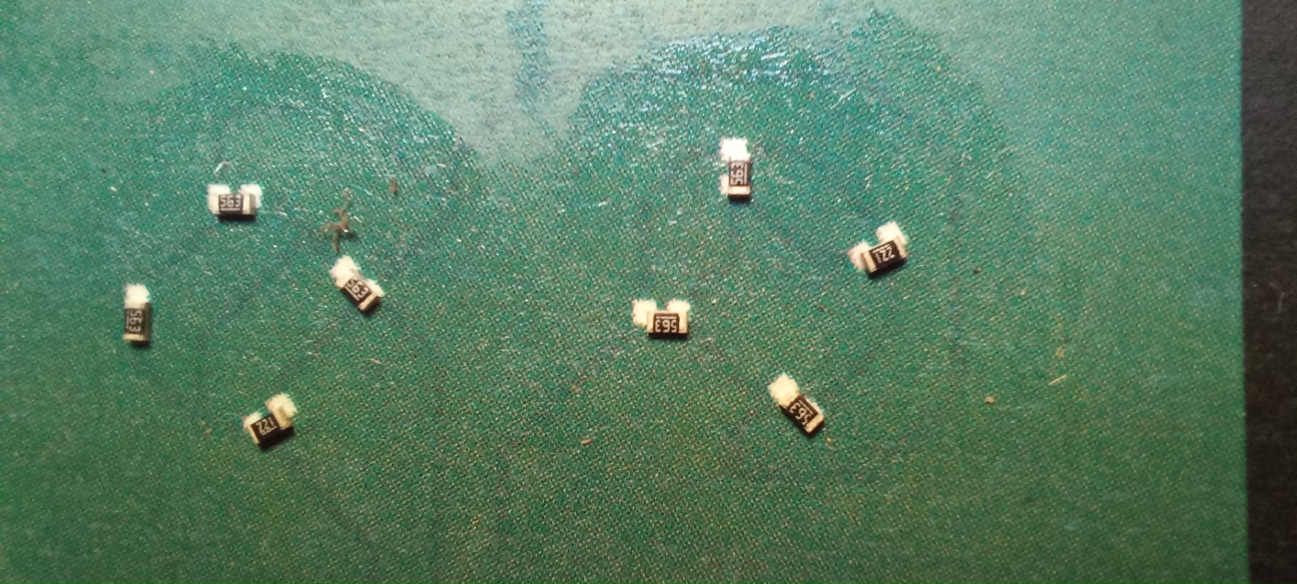
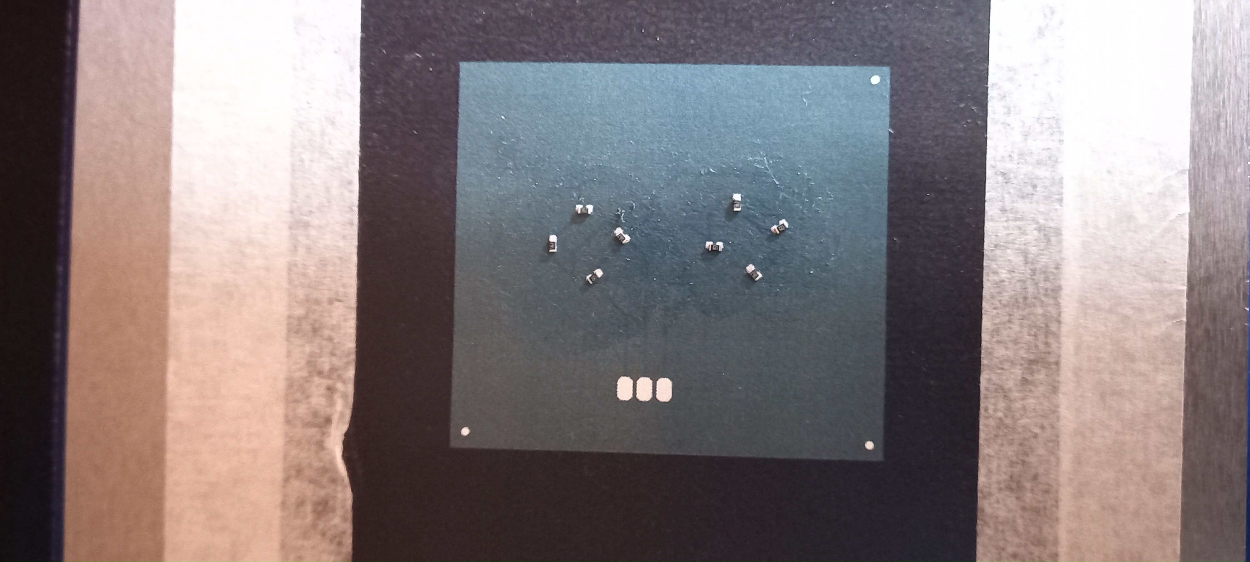
( this is 2 groups of 603 resistor from 2 different strip feeder)
Like you could see placement error is near same in the 2 groups, but are not same depended on rotation of the part. Placement use bottom camera.
well, my config :
- latest Openpnp version.
- camera calibration is ok and checked
- each axis deplacement is correct in size.
- nozzle offset was made and checked.
- nozzle tip calibration was made, and checked.
- fake pcb board and strip feeder are on the same plane (same height.)
- square compensation is made and checked.
- I check pipeline for each part in live and
the contour, center and orientation seem perfectly detected.
...
If I ask openpnp to place tool on fiducials, the tool is perfectly centered.
(my fake pcb use 3 fiducials, of course board location and feeder detection work perfectly).
a few days ago, I made placement (and since then I have completely redone my calibration ) with realy near the same result :

I realy dont know what to do now..
any suggestions are wellcome !
Thank you.
manu f
Oct 13, 2021, 4:26:21 PM10/13/21
to ope...@googlegroups.com
please look at that,
firstly after board fiducial check, I manually check camera position for all 3 fiducial:
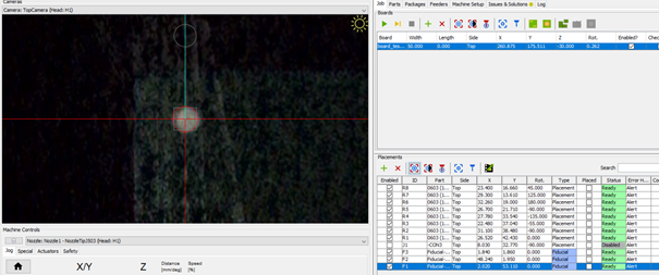
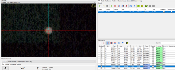
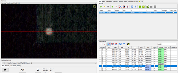
it look like not too bad!
then I move the camera to parts and ..
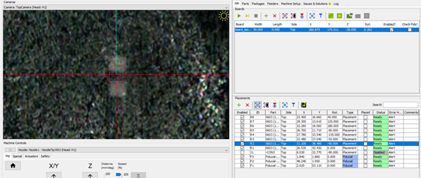
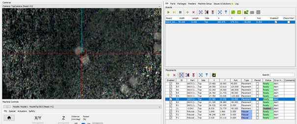
we could see there are some offset..
I check again my fake pcb by printing it on a tranparent (transparent film not move in size like paper)
but all is ok. Also even if the print is not perfect, the afine transformation with 3 fiducial must correct it, not ?
(Pick and place file come from altium designer 20)
So what could I check now ?
manu f
Oct 13, 2021, 5:01:36 PM10/13/21
to ope...@googlegroups.com, ma...@makr.zone
So I decide to calibrate the board not with fiducial but with parts and ...
tatata!! realy better than with fiducial !! (parts are not far from each other, so I use 3 parts and 1 fiducial to set the board position)
@ma...@makr.zone What do you think about that ? what could be wrong with fiducials board positionning ?
is 3 fiducial not enought ? is there a problem on my side ? could it be a problem on the afine transformation ?
Regards
Emmanuel

tonyl...@gmail.com
Oct 13, 2021, 6:16:04 PM10/13/21
to OpenPnP
The code that computes the affine transformation is the same for both methods (fiducials or parts) so it seems unlikely that the issue is there. The difference between the two methods is just how the data is collected: the fiducial method uses the vision system to locate the fiducials while the parts method used the human eye to locate the parts. Just to see what happens, could you try the parts method and just choose the three fiducials as the parts? Note that both methods support using more than three so can you also try and add a forth fiducial?
manu f
Oct 14, 2021, 1:10:10 AM10/14/21
to ope...@googlegroups.com
Thanks Tony for your return.
I will test your 2 suggestions.
( I am sure fiducial are well recognize and centering 'cause I checked it when processing).
--
You received this message because you are subscribed to the Google Groups "OpenPnP" group.
To unsubscribe from this group and stop receiving emails from it, send an email to openpnp+u...@googlegroups.com.
To view this discussion on the web visit https://groups.google.com/d/msgid/openpnp/d893459d-5021-47a3-bab3-826b3db4ddb5n%40googlegroups.com.

ma...@makr.zone
Oct 14, 2021, 11:34:31 AM10/14/21
to ope...@googlegroups.com
Hi manu f,
Some thoughts:
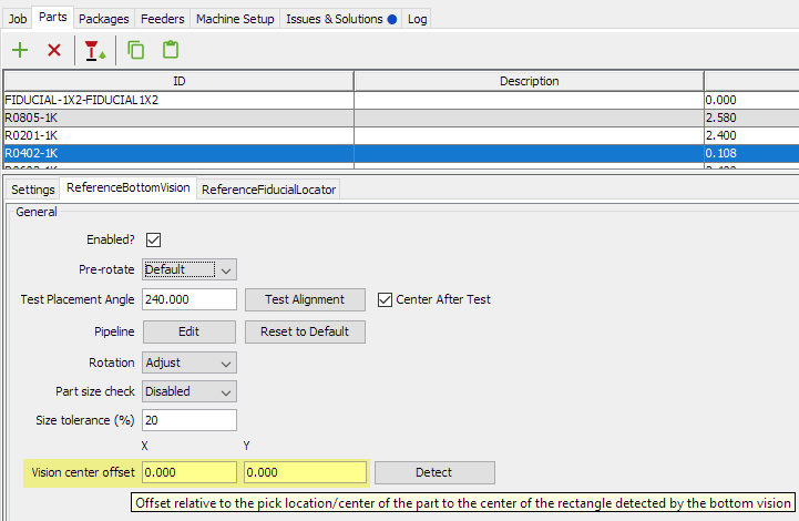
- Check that your part offsets are zero on the part.
- Check that the E-CAD library has the parts' origin
really in the center of the bounding rectangle around
the pads.
- Check that the E-CAD library has the fiducial's origin really in the center of the circle.
- Make 100% sure your exported/imported positions data is the same version that is used for printing the fake board. You would not be the first one to confuse an older/newer version.
- If you're using bottom vision: the bottom camera position
can also be a source of offsets.
_Mark
To view this discussion on the web visit https://groups.google.com/d/msgid/openpnp/CAGshWo3qTcWasCULTFOxvu9KFYhTaz2RZ8oGtJxLFTstDdUO3A%40mail.gmail.com.
manu f
Oct 14, 2021, 12:08:51 PM10/14/21
to ope...@googlegroups.com
Hi Mark,
Thank for your return,
I will check all your suggestions asap.
Regards
To view this discussion on the web visit https://groups.google.com/d/msgid/openpnp/1347dcb0-feb3-d022-fac4-bf4cafd7775b%40makr.zone.
manu f
Oct 18, 2021, 9:19:32 AM10/18/21
to ope...@googlegroups.com, ma...@makr.zone
1. Check that your part offsets are zero on the part
I confirm no offset.
- 2. Check that the E-CAD library has the parts' origin
really in the center of the bounding rectangle around
the pads.
- 3. Check that the E-CAD library has the fiducial's origin really in the center of the circle.
- I confirm parts origin in the center.
- 4. I am happy with my bottom camera position, and when my test with 3 parts and 1 fiducial components was centered.
Le jeu. 14 oct. 2021 à 17:34, ma...@makr.zone <ma...@makr.zone> a écrit :
To view this discussion on the web visit https://groups.google.com/d/msgid/openpnp/1347dcb0-feb3-d022-fac4-bf4cafd7775b%40makr.zone.
manu f
Oct 18, 2021, 5:08:48 PM10/18/21
to ope...@googlegroups.com, tonyl...@gmail.com
Wel today I had time to made some test again.
- I reprinted my fake PCB with 4 fiducials.
- I made again all calbrating, check all camera / tools positions, and made sqareness correction.
I made 2 test obe with 4 fiducial and 1 with 3 fiducial, and look good in these 2 cases..
(4 fiducials)
(use only 3 fiducials)
Well I certainly got an offset somewher last time.. I notice that my X axis is not as rigid as I want, and alignment of 2 motors is not same at each start (I take more care about that this time).
I plan to use mechanical stop to align my motors always same with a sequence lake that:
- move to home switch then go to 5 milimeters before X mechanical stop.
- move slowly 6 mm to the mechanical X stop (one of my motor will stall first then the other: like that I align my motors)
- move to home switch.
- finish with optical homing.
What do you think of that ?
how do you solve this dual motor alignment problem (I could not have a home switch on both X motor)?
Reply all
Reply to author
Forward
0 new messages