Board Z tolerance?

vespaman

mark maker
Can't say for the hardware side (nozzle travel etc.).
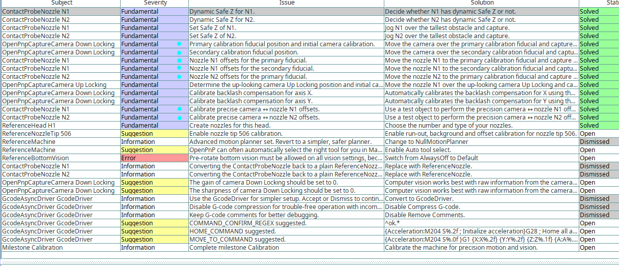
For the OpenPnP software side, this should be fine, as long as you redo Issues & Solutions primary & secondary fiducial calibration and nozzle <-> camera offsets calibration (confetti), with the primary fiducial on the new lower PCB surface. This will calibrate out any slight nozzle tilt you might have.
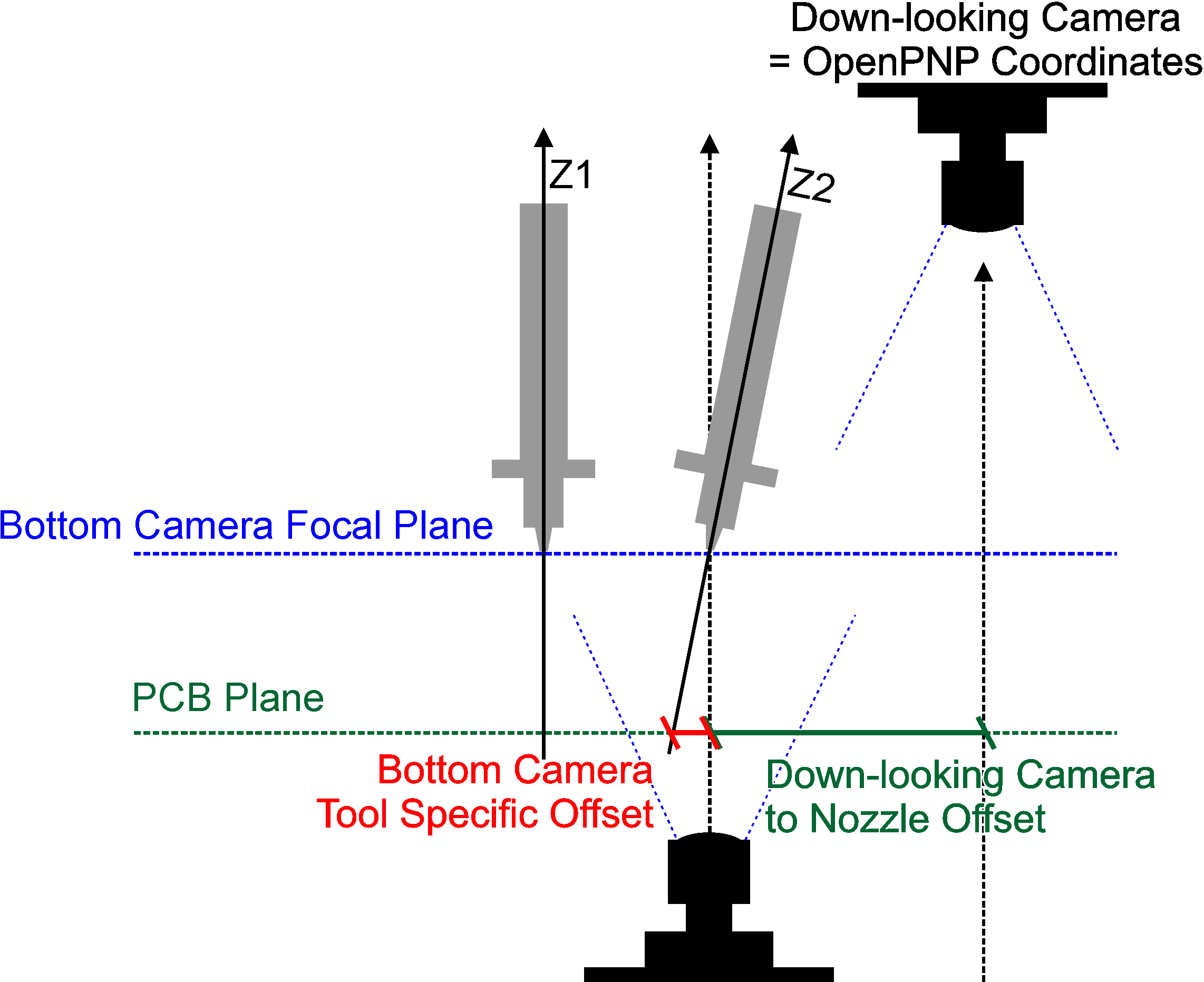
If I were you, and if it is technically possible, I would also try to adjust the bottom camera focal plane to match the new PCB surface Z, especially if the bottom camera has a wide angle lens. Then redo the bottom camera calibration(s) too.
When I say "camera calibration" I mean both the preliminary and advanced calibration (the latter can be optional, if it causes problems).
And this assumes you have nozzle tip calibration always active,
ideally setup by Issues & Solutions, so it will be
automatically refreshed to the new situation on the next
homing/nozzle tip change:
https://youtu.be/Pxg6g3KI5_E?t=188
_Mark
--
You received this message because you are subscribed to the Google Groups "OpenPnP" group.
To unsubscribe from this group and stop receiving emails from it, send an email to openpnp+u...@googlegroups.com.
To view this discussion on the web visit https://groups.google.com/d/msgid/openpnp/5ea41769-857d-46dd-a630-29630331e247n%40googlegroups.com.
vespaman
mark maker
> Would that be these seven marked i&s?
Yes.
> This is all saved in machine.xml, right? So if things takes a turn to the worse (can't see why, but better safe than sorry), I can just restore the currently working machine.xml.
Affirmative.
> The worrying thing I can think of, is that the feeders will now not be on the same level, which might make the vision system struggle more, but perhaps this is not an issue.
The problem is not vision, especially if you redo the Advanced Camera Calibration too, which handles camera Z tilt.
The problem is nozzle tilt, when the feeders are at different Z
height (i.e. the confetti test, which measures camera <->
nozzle offsets was done at a different Z). But for a few mm I
don't think it will be critical, tilt is usually low on this
commercial machines (this is more of a reminder for other users,
not to make any feeders that are centimeters above/below
PCB level).
> Esp if I leave focus plane of down looking camera where it is? (The new board Z only makes a very minor de-focus I can't see this will make any issues with the fiducials etc).
As long as all the calibrations are made, this does not matter
much, focus is not that important, tilt and Z dependent scale
a.k.a. 3D Units per Pixel are.
Personally, I would always go for the PCB focal level for the down-looking camera, assuming you can adjust the camera focus easily. Fiducials on the PCB are really important. The feeder vision is not that critical, any errors there will be compensated by bottom vision, and bottom vision in turn has compensation for nozzle tilt, assuming you use nozzle tip calibration too:
_Mark
To view this discussion on the web visit https://groups.google.com/d/msgid/openpnp/57dc1e7e-5f3f-4a3a-9dc6-e75e1b9d2aa8n%40googlegroups.com.
vespaman
mark maker
> Changing the focus on the down looking cam means basically redo the hole machine calibration on these machines, (drag pin/feeders etc)
Theoretically, it should not matter. Just carefully adjusting the focus a bit should not change the camera axis. I agree, in practice, the danger of somehow shifting the lens is there, but, even a shifted camera lens should cancel itself out through:
Camera shifted -> Visual Homing compensates for camera -> Camera to Nozzle offsets calibration compensates for nozzles.
So in the end, everything should remain the same, effectively.
The only caveat is that this all is only strictly true for that common
PCB surface Z level, where everything was calibrated before the
change. If you have large camera and/or nozzle tilt, it does
slightly change on different Z levels. Again, I don't think it
will in practice matter for the few mm you are talking about.
_Mark
To view this discussion on the web visit https://groups.google.com/d/msgid/openpnp/b1637628-9e19-4f5d-8d2c-b6cf55fc9274n%40googlegroups.com.
vespaman

mark maker
> But anyway, the down camera on the chmt's are impossible to work gently with
I see, that's why, when I proposed this, I wrote: "assuming you can adjust the camera focus easily." 😁
> the drag pin adjustment will go out the window
You're absolutely right, I was not thinking of that.
I'm not sure the pin can be accurately calibrated like that.
Maybe my impression is wrong, but I always thought these solenoids
are quite crude, they are not really engineered for this purpose.
I expect them to have quite a large play when extended, right?
Have you ever rattled it around when extended? When you jog to
the bottom camera from the right and extend, and jog from the left
and extend, does it appear at the same position?
But the play does not really matter, because I expect the pin is
thin and the sprocket hole is large, so inserting it is not a
problem if you aim for the center. They only expose their repeatable
positional property, when actually under load, i.e. when the
pin is wedged against its shaft, so the whole thing is
mechanically defined for the first time.
Exaggerated illustration (some of that could also be flex):

As a conclusion: any calibration attempt would have to be under
load. Perhaps dragging an object, which has high friction/mass,
and a central "sprocket" hole in all four directions, then
finding the hole with the camera each time. The centroid of these
four would give you the real center, and you could derive an
"under-load" diameter of the pin (which could even be negative, if
the play is large!). This would have to happen at the same Z as
the feeders, as the play/flex is likely dependent on pin
extension.
_Mark
To view this discussion on the web visit https://groups.google.com/d/msgid/openpnp/cf31aa41-7c8f-44e3-828a-4a930e60ca14n%40googlegroups.com.
vespaman
mark maker
> I don't remember if it is the FW or openPnP that is hindering a move once the drag pin gets stuck, but I guess it is not in the fw, so I suppose that is a way forward. Perhaps even by manually jogging (carefully)? Maybe that could be a first step - to be able to manually override/ignore a stuck drag pin, and to allow small (0.01/0.1) jogs.
I don't understand what exactly you want to say, sorry.
But AFAIK nothing is in the firmware (it is a Smoothieware port),
instead the drag interlock is done in OpenPnP using Actuator Axis
Interlock. I don't know how exactly it is modeled in the CHMT
machines, but this is the Wiki example config:

And as you see at the bottom of the screenshot, you can set a speed
range, where the confirmation is needed. With a speed
outside that range, motion is still admissible.
So if you were asking about how to do such a calibration manually (?), just pull down the Speed % slider on the Machine Controls to ~20%, for instance.
But when I described the calibration process in my email, I was
thinking about a possible/future automatic
calibration, similar to the "confetti" test.
_Mark
To view this discussion on the web visit https://groups.google.com/d/msgid/openpnp/9e9c3852-d593-48df-99b5-06700859b43en%40googlegroups.com.
vespaman
mark maker
> But as you probably know, once the drag pin gets stuck down in a sprocket hole...
No, I don't have any practical experience myself. I only made the
Interlock according to the various requests of users. Drag pin was
just one of many applications. And in the end they said it was
working (Nélio Oliveira). Unfortunately, his video is no longer
available:
https://groups.google.com/g/openpnp/c/CQX0uDciXp8/m/egCXht0VAgAJ
> And since there will be a lot of sticking if a real sprocket hole where to be used for calibrating the drag pin coordinates...
Why?
As far as I understand (or as I intended it), the interlock is
only active, if the pin did not obey the command to pull back. As
long as the actuator to extend the pin is true, there is no
interlock and you can jog as you like.
And If you are using the PushPullFeeder, I assume you will add a
small move back towards the center of the sprocket hole, before
retracting the pin, so it relieves the tension, and should not be
stuck.
The same would of course be done in the calibration routine.
> ... it needs to be possible to move the tool head even if the drag pin is stuck.
In case it is still stuck: Have you read what I wrote about the Speed %? How is it configured now? Does this currently work? Or not?
_Mark
To view this discussion on the web visit https://groups.google.com/d/msgid/openpnp/61aca813-d21b-4ffb-b345-8fbb41fa8bf5n%40googlegroups.com.

Jan
I'm sorry to intercept your discussions about the drag pin, but I would
like to put my five cents in:
- I'm using the axis interlock feature and its part of my example
machine.xml. To me this is really useful as it already as prevented a
few situations where I otherwise would have damaged the pin.
- Just to recap: the axis interlock feature works the way that the drag
pin feedback has to report that the pin is in its up position before the
machine moves on. This is/shall be validated only when the drag pin is
switched off/retracted. (I'm not sure about the last statement. IIRC
I've seen more then the expected amount of entries in the log. I'll have
to check that again.) However, one can comment any movement while the
pin is down (I've personal experience with that as well...).
- The position calibration can probable not be automated due to the play
and different Z levels. The position has to be configured at feeder Z
while the pin can either be retracted (Z > Z_feeder) or extended (Z <
Z_feeder). I configured the cores location using some putty at PCB-Z and
the fine location using "acoustic feedback": if the position is good,
the pin sounds more metallic when going down into a tape hole. If the
location is bad, its sound is damped by the tap.
- The distance required to go back to safely retract the drag pin can be
configured/measured using tape holes: if the distance is good, the pin
will exactly hit the next hole on the next feed operation. Please keep
in mind, that this distance is tape and speed (acceleration?) dependent.
(I use 0.2..0.4mm)
- I once had transparent plastic tape where the tape holes where moving
in Y. Every 20..50 parts I had to slightly adjust the tape holes Y
location by ~0.3mm for correct drag operation. So there might be drag
pin issues, that can not be prevented by careful calibration. However,
the axis interlock feature is very helpful in this situations and thanks
to the forgiving job processor one can make any modification to the
feeder and safely resume the job.
Jan
> so I suppose that is a way forward. Perhaps even by manually jogging
> (carefully)? Maybe that could be a first step - to be able to
> manually override/ignore a stuck drag pin, and to allow small
> I don't understand what exactly you want to say, sorry.
>
> But AFAIK nothing is in the firmware (it is a Smoothieware port),
> instead the drag interlock is done in OpenPnP using Actuator Axis
> Interlock. I don't know how exactly it is modeled in the CHMT
> machines, but this is the Wiki example config:
>
>
> Drag Pin Confirm
>
> And as you see at the bottom of the screenshot, you can set a *speed
> range*, where the confirmation is needed. With a speed outside that
>
> So if you were asking about how to do such a calibration manually
>
> But when I described the calibration process in my email, I was
>
> _Mark
>
>
> On 5/25/23 11:05, vespaman wrote:
>> can adjust the camera focus easily." 😁/
>> against changing focus of the camera as such, just that the
>> implications are big.. :-)
>>
>> Regarding the solenoid/dragpin;
>>
>> I think first of all, there's the mounting angle error of the
>> solenoid, and also the actual mounting position (it is held in
>> place by two screws, there's some play here, of course, before
>> they are tightened).
>> Then, we have the runtime play. However, once the dragpin is down,
>> it is pretty solid, since the magnetic strength is high, so no
>> rattling (but this may be individually different). I am not sure
>> if the play while going down is relevant in actual operation,
>> since if it is, the somewhat pointy dragpin should then anyway
>> steer the plunger into the sprocket hole (which I think you are
>> become less and less, as the plunger enters fully the coil. (But
>> if I pull down the drag pin by hand, I can still feel a noticeable
>> play - like you say, it is not a precision thing, exactly :-) )
>> In my case I had to adjust the drag pin coordinates in Y direction
>> in two iterations from the initial carbon copy solution, IIRC,
>> since it was stuck once fully down, in to the tape sprocket hole.
>>
>> Actually using a sprocket hole for determining the optimal center
>> position is probably the best way of doing it, like you say. I
>> don't remember if it is the FW or openPnP that is hindering a move
>> once the drag pin gets stuck, but I guess it is not in the fw, so
>> I suppose that is a way forward. Perhaps even by manually jogging
>> (carefully)? Maybe that could be a first step - to be able to
>> manually override/ignore a stuck drag pin, and to allow small
>> (0.01/0.1) jogs.
>>
>> Anyway, at some point I will have to do this again, I know that... :-o
>>
>>
>> Cheers,
>> Micael
>>
>> torsdag 25 maj 2023 kl. 10:22:01 UTC+2 skrev ma...@makr.zone:
>>
>> work gently with/
>>
>> I see, that's why, when I proposed this, I wrote: /"assuming
>> you can adjust the camera focus easily." 😁/
>>
>> /> the drag pin adjustment will go out the window/
>> You're absolutely right, I was not thinking of that.
>>
>> I'm not sure the pin can be accurately calibrated like that.
>> Maybe my impression is wrong, but I always thought these
>> solenoids are quite crude, they are not really engineered for
>> this purpose. I expect them to have quite a large play when
>> extended, right?
>>
>> Have you ever rattled it around when extended? When you jog to
>> the bottom camera from the right and extend, and jog from the
>> left and extend, does it appear at the same position?
>>
>> But the play does not really matter, because I expect the pin
>> is thin and the sprocket hole is large, so inserting it is not
>> a problem if you aim for the center. They only expose their
>> thing is mechanically defined for the first time.
>>
>> Exaggerated illustration (some of that could also be flex):
>>
>>>
>>> Screenshot_20230525_080419.png
>>>
>>>
>>> I think I will change my down camera at some point, because
>>> it is just about doing its job, there are better solutions
>>> out there.
>>>
>>>
>>> - Micael
>>>
>>> onsdag 24 maj 2023 kl. 15:17:08 UTC+2 skrev ma...@makr.zone:
>>>
>>>
>>> /Theoretically/, it should not matter. Just carefully
>>> axis. I agree, in practice, the danger of somehow
>>> shifting the lens is there, but, even a shifted camera
>>> lens should cancel itself out through:
>>>
>>> Camera shifted -> Visual Homing compensates for camera ->
>>> Camera to Nozzle offsets calibration compensates for nozzles.
>>>
>>> So in the end, everything should remain the same,
>>> The only caveat is that this all is only strictly true
>>> camera and/or nozzle tilt, it does slightly change on
>>> different Z levels. Again, I don't think it will in
>>> practice matter for the few mm you are talking about.
>>>
>>> _Mark
>>>
>>>
>>>> OK, again, thanks for acknowledging!
>>>>
>>>> Agree on focus on PCB, but..
>>>>
>>>> Changing the focus on the down looking cam means
>>>> basically redo the hole machine calibration on these
>>>> machines, (drag pin/feeders etc) which is not something
>>>> I have the time to do now. (and in fact, I feel slightly
>>>> sick, thinking about it :) ). Hopefully, the fiducial
>>>> lock-ins will work just as fine. At some point, I want a
>>>> better down looking camera, than the one I have, further
>>>> away, and with longer focus depth.
>>>>
>>>> - Micael
>>>>
>>>> onsdag 24 maj 2023 kl. 14:43:52 UTC+2 skrev ma...@makr.zone:
>>>>
>>>>
>>>> Yes.
>>>>
>>>> /> This is all saved in machine.xml, right? So if
>>>> better safe than sorry), I can just restore the
>>>>
>>>> Affirmative.
>>>>
>>>> /> The worrying thing I can think of, is that the
>>>> might make the vision system struggle more, but
>>>> The problem is not vision, especially if you redo
>>>> the Advanced Camera Calibration too, which handles
>>>> camera Z tilt.
>>>>
>>>> The problem is nozzle tilt, when the feeders are at
>>>> different Z height (i.e. the confetti test, which
>>>> measures camera <-> nozzle offsets was done at a
>>>> different Z). But for a few mm I don't think it will
>>>> be critical, tilt is usually low on this commercial
>>>> machines (this is more of a reminder for other
>>>> users, not to make any feeders that are
>>>>
>>>> /> //Esp if I leave focus plane of down looking
>>>> very minor de-focus I can't see this will make any
>>>> As long as all the calibrations are made, this does
>>>> not matter much, focus is not that important, tilt
>>>> and Z dependent scale a.k.a. 3D Units per Pixel are.
>>>>
>>>> Personally, I would always go for the PCB focal
>>>> level for the down-looking camera, assuming you can
>>>> adjust the camera focus easily. Fiducials on the PCB
>>>> are really important. The feeder vision is not that
>>>> critical, any errors there will be compensated by
>>>> bottom vision, and bottom vision in turn has
>>>> compensation for nozzle tilt, assuming you use
>>>> nozzle tip calibration too:
>>>>
>>>>
>>>> https://github.com/openpnp/openpnp/wiki/Nozzle-Tip-Calibration-Setup#what-is-the-bottom-camera-location-and-how-can-it-vary-between-nozzles <https://github.com/openpnp/openpnp/wiki/Nozzle-Tip-Calibration-Setup#what-is-the-bottom-camera-location-and-how-can-it-vary-between-nozzles>
>>>>
>>>> _Mark
>>>>
>>>>
>>>> On 5/24/23 13:34, vespaman wrote:
>>>>> Thanks Mark!
>>>>>
>>>>> primary & secondary fiducial calibration and nozzle
>>>>> <-> camera offsets calibration (confetti), with
>>>>> surface.* This will calibrate out any slight nozzle
>>>>>
>>>>> Would that be these seven marked i&s?
>>>>>
>>>>> travel etc.).
>>>>>
>>>>> For the OpenPnP *software* side, this should be
>>>>> primary & secondary fiducial calibration and
>>>>> nozzle <-> camera offsets calibration
>>>>> new lower PCB surface.* This will calibrate out
>>>>>
>>>>> If I were you, and if it is technically
>>>>> possible, I would also try to adjust the bottom
>>>>> camera focal plane to match the new PCB surface
>>>>> Z, especially if the bottom camera has a wide
>>>>> angle lens. Then redo the bottom camera
>>>>> calibration(s) too.
>>>>>
>>>>> When I say "camera calibration" I mean both the
>>>>> --
>>>>> You received this message because you are
>>>>> subscribed to the Google Groups "OpenPnP" group.
>>>>> To unsubscribe from this group and stop receiving
>>>>> emails from it, send an email to
>>>>> openpnp+u...@googlegroups.com.
>>>>> To view this discussion on the web visit
>>>> --
>>>> You received this message because you are subscribed to
>>>> the Google Groups "OpenPnP" group.
>>>> To unsubscribe from this group and stop receiving emails
>>>> from it, send an email to openpnp+u...@googlegroups.com.
>>>> To view this discussion on the web visit
>>> --
>>> You received this message because you are subscribed to the
>>> Google Groups "OpenPnP" group.
>>> To unsubscribe from this group and stop receiving emails from
>>> it, send an email to openpnp+u...@googlegroups.com.
>>> To view this discussion on the web visit
>> --
>> You received this message because you are subscribed to the Google
>> Groups "OpenPnP" group.
>> To unsubscribe from this group and stop receiving emails from it,
>> send an email to openpnp+u...@googlegroups.com.
>> To view this discussion on the web visit
> --
> You received this message because you are subscribed to the Google
> Groups "OpenPnP" group.
> To unsubscribe from this group and stop receiving emails from it, send
> an email to openpnp+u...@googlegroups.com
vespaman
>> But as you probably know, once the drag pin gets stuck down in a sprocket hole...
>No, I don't have any practical experience myself. I only made the
Interlock according to the various requests of users. Drag pin was
just one of many applications. And in the end they said it was
working
>> And since there will be a lot of sticking if a real sprocket hole where to be used for calibrating the drag pin coordinates...
>Why?
Well, I thought that the idea was to drag something in different directions, and release the drag pin? If you release it and it is touching the tape too much, it will stick down, and the software will have to move around (preferably back from the direction it came) until it is freed again, disregarding interlock. But maybe you had another idea on how to do the automatic calibration? With vision? Still you need to "un-stick" the drag pin.
>As far as I understand (or as I intended it), the interlock is only active, if the pin did not obey the command to pull back.
Exactly. But if it gets stuck, it cant move back, so... The pin is only pulled back with a weak spring, so if there's any kind of tension it till not move back. So interlock is dealing with this under normal runs, and stops the job (=Good). But now, once it has stuck the operator can't move the head, other than manually pushing it or the tape so the pin gets free, and interlock "released". You can't manually jog out of this situation?
vespaman
>machine.xml. To me this is really useful as it already as prevented a
>few situations where I otherwise would have damaged the pin.
>configured/measured using tape holes: if the distance is good, the pin
>will exactly hit the next hole on the next feed operation. Please keep
>in mind, that this distance is tape and speed (acceleration?) dependent.
>(I use 0.2..0.4mm)
>the axis interlock feature is very helpful in this situations and thanks
>to the forgiving job processor one can make any modification to the
>feeder and safely resume the job.
mark maker
You best send the machine.xml, then I can check the interlock config.
But ... (this seems stuck under the carpet) ... what about the Speed % ? Have you ever tried?
You do understand what the idea is, right? To quote from the
Wiki:
"The example interlock makes an exception for very slow movement. This might be useful in order to try and gently de-block a stuck pin."
_Mark
To view this discussion on the web visit https://groups.google.com/d/msgid/openpnp/535f6e06-60fa-4df2-9c4f-3a257f32412en%40googlegroups.com.