Setting up bottom vision

vespaman

Jan
I'm not a vision expert myself but will try to explain what I've
learned so far and how I'm understanding the (new) setup.
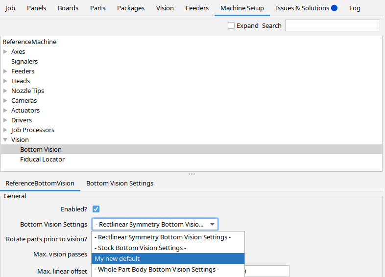
The vision part in the machine tree is the old representation which is
superseded be the "Vision" tab you found. The two vision pipelines
starting with a "- " you see are part of the stock OpenPnP setup. They
are read-only and serve as starting points to create more specific
pipelines. "- Rectlinear Symmetry Bottom Vision Settings -" is assigned
to "Bottom Vision", which means, its the default for all parts/packages
that do not have more specific settings. On my setup "Bottom Vision" is
assigned to a pipeline named "- Default Machine Bottom Vision -" which
is derived from "- Rectlinear Symmetry Bottom Vision Settings -" (I
checked the pipeline stages to find out) and can be edited. I used this
to configure the defaults to work for most of my parts.
Once you're satisfied with the default and find, that some part or
package is not handled well, you can go to that part or package and
change its "Bottom Vision Settings" using the tab by the same name.
You'll see the same information as in the Vision tab. In addition you'll
see the name of the Vision Setting, that is used for that part/package
and have two bottoms (in the line "Manage Settings") to specialize the
settings or revert them to the default. If you use the "specialize"
button, a copy of the current setting will be generated and assigned to
that part/package. If you now change any of the settings, they will be
specific to that package/part only. This feature is very helpful because
you can - whenever a bottom vision operation failed - check why and then
make the required adjustments, either to a pipeline, that might be
shared with other parts/packages or just to that specific part/package.
Internally the "Specialize for x" and "Reset to Default" bottom will
create or remove an entry from the table on the Vision tab and update
the corresponding "assigned to" fields. That's why I would recommend to
manage bottom vision settings using their tab on the parts/packages tab.
There is a third button in "Manage Settings" line which allows you to
generalize a setting you created for part to all parts using the same
package.
Unfortunately I don't remember how my "- Default Machine Bottom Vision
-" was created. I guess you could specialize the setting (which shall
create a editable new set of settings) and then (on the Vision tab)
rename it as you like and assign it to "Bottom Vision". Then you shall
have editable default settings.
Jan
On 28.03.2023 16:55, vespaman wrote:
> Hi guys,
>
>
> So I'm trying to follow this guide
> https://github.com/openpnp/openpnp/wiki/Bottom-Vision, in order to get
> my bottom vision working, or work better.
>
> I guess the docs are not updated to the version that I am running,
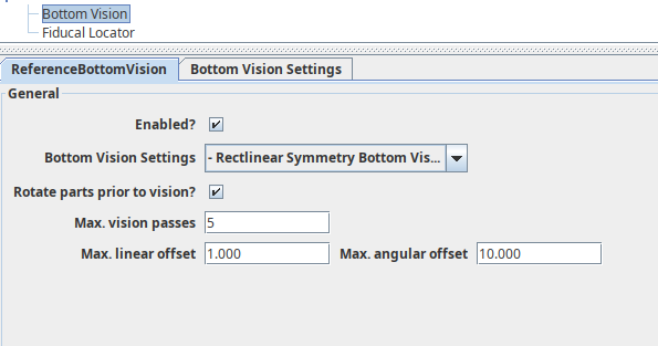
> because when I orient myself to "Machine Setup -> Vision -> Bottom
> Vision", I am presented with a ui like this instead (or maybe the UI has
> changed since my last update a week ago?)
>
>
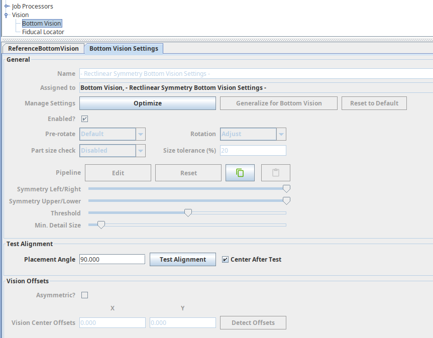
> So, no biggie I have another tab instead. But there's nothing I can do
> on the next tab, apart from "optimize" or "Test alignment";
>
> So I instead, without any clue what I was doing, I started to look at
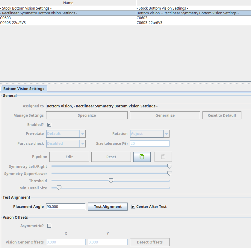
> the main "Vision" tab instead. Here there are two "Stock and Rectlinear"
> that also cannot be edited, I suppose these are some kind of fixed defaults.
>
>
> But the ones called 0603 can be edited, so I tried to understand those,
> I guess I must have accidentally created them on some occasion, of if
> they followed some machine.xml.
> But anyway, when I did try to do that, I had no part on my nozzle, so I
> decided to move the head out side the up looking camera for some reason
> that I have forgotten, and broken yet another nozzle since it was below
> safe Z. [note to self; always buy 502 nozzles in packs of 10].
> Fortunately I have one more green 502, so I can continue, but now I
> think it is better to do things in the proper order instead of just
> trying to figure out things randomly... :-)
>
> So I guess, the question number one is; how can I follow the Bottom
> Vision docs, or are there any other place I can read about bottom vision
> setup? Is there something in my setup that makes the setting greyed out?
>
> - Micael
>
> You received this message because you are subscribed to the Google
> Groups "OpenPnP" group.
> To unsubscribe from this group and stop receiving emails from it, send
> an email to openpnp+u...@googlegroups.com
> <mailto:openpnp+u...@googlegroups.com>.
> To view this discussion on the web visit
> https://groups.google.com/d/msgid/openpnp/8210f71d-7e12-466f-9800-210296195a75n%40googlegroups.com <https://groups.google.com/d/msgid/openpnp/8210f71d-7e12-466f-9800-210296195a75n%40googlegroups.com?utm_medium=email&utm_source=footer>.
Jan
>
>
> So I'm trying to follow this guide
> https://github.com/openpnp/openpnp/wiki/Bottom-Vision, in order to get
> my bottom vision working, or work better.
>
> I guess the docs are not updated to the version that I am running,
> because when I orient myself to "Machine Setup -> Vision -> Bottom
> Vision", I am presented with a ui like this instead (or maybe the UI has
> changed since my last update a week ago?)
>
>
> So, no biggie I have another tab instead. But there's nothing I can do
> on the next tab, apart from "optimize" or "Test alignment";
>
> So I instead, without any clue what I was doing, I started to look at
> the main "Vision" tab instead. Here there are two "Stock and Rectlinear"
> that also cannot be edited, I suppose these are some kind of fixed defaults.
>
>
> But the ones called 0603 can be edited, so I tried to understand those,
> I guess I must have accidentally created them on some occasion, of if
> they followed some machine.xml.
> But anyway, when I did try to do that, I had no part on my nozzle, so I
> decided to move the head out side the up looking camera for some reason
> that I have forgotten, and broken yet another nozzle since it was below
> safe Z. [note to self; always buy 502 nozzles in packs of 10].
> Fortunately I have one more green 502, so I can continue, but now I
> think it is better to do things in the proper order instead of just
> trying to figure out things randomly... :-)
>
> So I guess, the question number one is; how can I follow the Bottom
> Vision docs, or are there any other place I can read about bottom vision
> setup? Is there something in my setup that makes the setting greyed out?
>
> - Micael
>
vespaman

mark maker
Hi,
Finally, I more or less rewrote the Wiki on that:
https://github.com/openpnp/openpnp/wiki/Bottom-Vision
Tell me what you think, contributions always welcome.
Side remark: Jan is using the Rectlinear Symmetry
variety as his default (that in itself is not the OpenPnP
factory default). Rectlinear Symmetry is of course a
powerful option (and I had high hopes for it), but it turned out
to have huge computation demands, so unless you have a very fast
computer, I'd say stick to the Stock pipeline now
explained in the Wiki. The Stock pipeline also has the
advantage of being compatible with Multi-Shot Vision, e.g.
for aligning parts larger than the camera view, which Rectlinear
Symmetry is not (yet).
Hint to all:
If your Bottom Vision does not work like in the following animation, you are missing out:

_Mark
--
You received this message because you are subscribed to the Google Groups "OpenPnP" group.
To unsubscribe from this group and stop receiving emails from it, send an email to openpnp+u...@googlegroups.com.
To view this discussion on the web visit https://groups.google.com/d/msgid/openpnp/8210f71d-7e12-466f-9800-210296195a75n%40googlegroups.com.
Jan
Many thanks for updating the Wiki. The page is much better now. Would
you please have a look again onto the screenshot Micael posted as part
of his question. In the list of Bottom Visions Settings he seems not to
have a "- Default Machine Bottom Vision -" entry and his "- Rectlinear
Symmetry Bottom Vision Settings -" seems to reference "Bottm Vision" and
itself. Recovering "- Default Machine Bottom Vision -" is not covered by
the Wiki yet. I think that would be only needed if Micael's situation is
something that a normal user can run into. If e.g. "- Default Machine
Bottom Vision -" can not be deleted anymore, this is likely somethine he
has to solve manually.
Jan
On 29.03.2023 11:11, mark maker wrote:
> Hi,
>
> Finally, I more or less rewrote the Wiki on that:
>
> https://github.com/openpnp/openpnp/wiki/Bottom-Vision
>
> Tell me what you think, contributions always welcome.
>
> default (that in itself is *not* the OpenPnP factory default).
> *Rectlinear Symmetry* is of course a powerful option (and I had high
> pipeline now explained in the Wiki. The *Stock* pipeline also has the
> advantage of being compatible with *Multi-Shot Vision*, e.g. for
> aligning parts larger than the camera view, which *Rectlinear Symmetry*
> is not (yet)*.
> *
>
> *Hint to all: *
> If your Bottom Vision does not work like in the following animation, you
> are missing out:
>
>
> _Mark
>
>
> On 3/28/23 16:55, vespaman wrote:
>> Hi guys,
>>
>>
>> So I'm trying to follow this guide
>> https://github.com/openpnp/openpnp/wiki/Bottom-Vision, in order to get
>> my bottom vision working, or work better.
>>
>> I guess the docs are not updated to the version that I am running,
>> because when I orient myself to "Machine Setup -> Vision -> Bottom
>> Vision", I am presented with a ui like this instead (or maybe the UI
>> has changed since my last update a week ago?)
>>
>>
>> So, no biggie I have another tab instead. But there's nothing I can do
>> on the next tab, apart from "optimize" or "Test alignment";
>>
>> So I instead, without any clue what I was doing, I started to look at
>> the main "Vision" tab instead. Here there are two "Stock and
>> Rectlinear" that also cannot be edited, I suppose these are some kind
>> of fixed defaults.
>>
>>
>> But the ones called 0603 can be edited, so I tried to understand
>> those, I guess I must have accidentally created them on some occasion,
>> of if they followed some machine.xml.
>> But anyway, when I did try to do that, I had no part on my nozzle, so
>> I decided to move the head out side the up looking camera for some
>> reason that I have forgotten, and broken yet another nozzle since it
>> was below safe Z. [note to self; always buy 502 nozzles in packs of 10].
>> Fortunately I have one more green 502, so I can continue, but now I
>> think it is better to do things in the proper order instead of just
>> trying to figure out things randomly... :-)
>>
>> So I guess, the question number one is; how can I follow the Bottom
>> Vision docs, or are there any other place I can read about bottom
>> vision setup? Is there something in my setup that makes the setting
>> greyed out?
>>
>> - Micael
>> --
>> You received this message because you are subscribed to the Google
>> Groups "OpenPnP" group.
>> To unsubscribe from this group and stop receiving emails from it, send
>> an email to openpnp+u...@googlegroups.com.
>> To view this discussion on the web visit
> --
> You received this message because you are subscribed to the Google
> Groups "OpenPnP" group.
> To unsubscribe from this group and stop receiving emails from it, send
> an email to openpnp+u...@googlegroups.com
Jan
Many thanks for updating the Wiki. The page is much better now. Would
you please have a look again onto the screenshot Micael posted as part
of his question. In the list of Bottom Visions Settings he seems not to
have a "- Default Machine Bottom Vision -" entry and his "- Rectlinear
covered by the Wiki yet. I think that would be only needed if Micael's
situation is something that a normal user can run into. If e.g. "-
Default Machine Bottom Vision -" can not be deleted anymore, this is
Jan
On 29.03.2023 11:11, mark maker wrote:
>
> Finally, I more or less rewrote the Wiki on that:
>
> https://github.com/openpnp/openpnp/wiki/Bottom-Vision
>
> Tell me what you think, contributions always welcome.
>
> default (that in itself is *not* the OpenPnP factory default).
> pipeline now explained in the Wiki. The *Stock* pipeline also has the
> advantage of being compatible with *Multi-Shot Vision*, e.g. for
> aligning parts larger than the camera view, which *Rectlinear Symmetry*
> is not (yet)*.
> *
>
> *Hint to all: *
>
> are missing out:
>
>
> _Mark
>
>
> On 3/28/23 16:55, vespaman wrote:
>> Hi guys,
>>
>>
>> So I'm trying to follow this guide
>> https://github.com/openpnp/openpnp/wiki/Bottom-Vision, in order to get
>> my bottom vision working, or work better.
>>
>> I guess the docs are not updated to the version that I am running,
>> because when I orient myself to "Machine Setup -> Vision -> Bottom
>> Vision", I am presented with a ui like this instead (or maybe the UI
>> has changed since my last update a week ago?)
>>
>>
>> So, no biggie I have another tab instead. But there's nothing I can do
>> on the next tab, apart from "optimize" or "Test alignment";
>>
>> So I instead, without any clue what I was doing, I started to look at
>> the main "Vision" tab instead. Here there are two "Stock and
>> Rectlinear" that also cannot be edited, I suppose these are some kind
>> of fixed defaults.
>>
>>
>> But the ones called 0603 can be edited, so I tried to understand
>> those, I guess I must have accidentally created them on some occasion,
>> of if they followed some machine.xml.
>> But anyway, when I did try to do that, I had no part on my nozzle, so
>> I decided to move the head out side the up looking camera for some
>> reason that I have forgotten, and broken yet another nozzle since it
>> was below safe Z. [note to self; always buy 502 nozzles in packs of 10].
>> Fortunately I have one more green 502, so I can continue, but now I
>> think it is better to do things in the proper order instead of just
>> trying to figure out things randomly... :-)
>>
>> So I guess, the question number one is; how can I follow the Bottom
>> Vision docs, or are there any other place I can read about bottom
>> vision setup? Is there something in my setup that makes the setting
>> greyed out?
>>
>> - Micael
>> --
>> You received this message because you are subscribed to the Google
>> Groups "OpenPnP" group.
>> To unsubscribe from this group and stop receiving emails from it, send
>> an email to openpnp+u...@googlegroups.com.
>> To view this discussion on the web visit
> --
> You received this message because you are subscribed to the Google
> Groups "OpenPnP" group.
> To unsubscribe from this group and stop receiving emails from it, send
> an email to openpnp+u...@googlegroups.com
mark maker
Hi Jan,
For the understanding: "- Default Machine Bottom Vision - " (unlike the others with the "-") is not a factory setting, but simply the default vision setting that was found in the configuration when the system upgraded OpenPnP to the Vision Settings system. For new configurations it is identical to the Stock settings, but already cloned so it can be edited.
If yours is gone, simply go to the Vision tab, select the Stock (or other) settings, press Copy and press Paste:
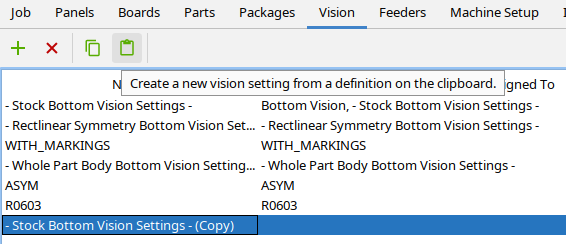
Then you can rename the Copy as you like in the table cell (F2) and assign it in Machine Setup / Vision / Bottom Vision.
Is this needed in the Wiki?
I considered this rather generic OpenPnP GUI usage, but certainly my "developer viewpoint" is not to be trusted 😅
In the Wiki, it is always a balance between too much information, where you lose your readers before they went through the important stuff, and too little 😎
_Mark
vespaman
vespaman
I will probably avoid SOT23 going forward, new designs, it is an ancient package, that is nice to hand solder, but that's about it.
mark maker
Thanks Micael,
I have made some adjustments re your 1.
https://github.com/openpnp/openpnp/wiki/Bottom-Vision#parts-too-big-for-camera
and also this:
https://github.com/openpnp/openpnp/wiki/Bottom-Vision#troubleshooting
Re your 3.
https://github.com/openpnp/openpnp/wiki/Bottom-Vision#global-configuration
But I agree this is still (and always will be) incompletely revised, not only here but elsewhere too.
Re your 2. there is talk about a new documentations system that
(if I understand correctly) is versioned, so we can revise
everything without regard to old OpenPnP version. Users/readers
can still go back to the older Wiki version.
https://github.com/openpnp/openpnp/issues/1537
As always: contribution are welcome!!
_Mark
To view this discussion on the web visit https://groups.google.com/d/msgid/openpnp/003c3a18-0a05-4c50-b79b-11c748ecc290n%40googlegroups.com.
mark maker
> Is there a way to measure/compare between the two?
If you edit the pipeline, each stage shows its computation time. The computations time is largely dependent on the search range (from the nozzle tip pick tolerance) and mask diameter (from the nozzle tip max. part diameter). If you set both tight (which is easy for 0402) then it will be no problem.
> The rectlinear, seems _much_ more forgiving when it comes
to the tweaking - almost regardless of what I do, it will work.
:-)
That was the intention. Robust, self-tuning. 😎
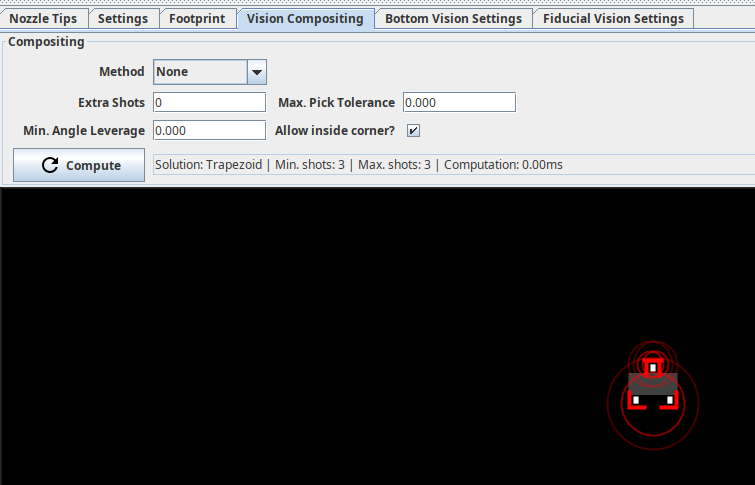
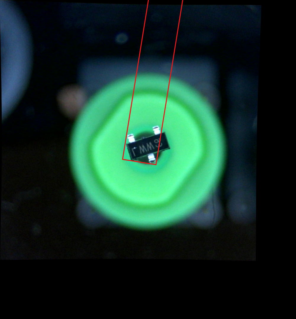
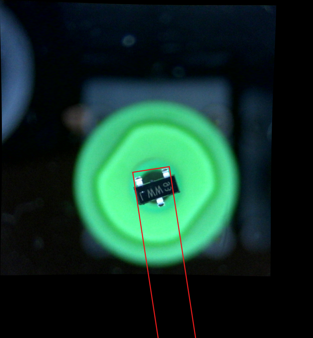
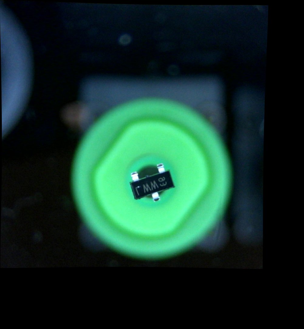
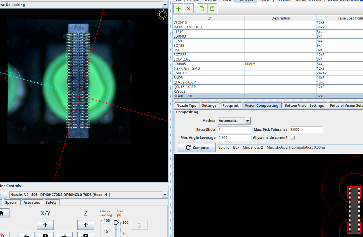
But there were still some tough nuts I could not make rock solid. One example is exactly the three-legged SOT23 with roundish pads you mention.
Then I made the Vision Compositing / Multi-Shot and this gives you an alternative for SOT23 and the likes.
Watch the video linked below, but .... unfortunately, I
was very tired when I recorded that and kept stuttering about it.
The idea is to isolate the pins on each side separately
(two shots), and then align the part from the composited geometry.
We need to make the pick tolerance very small, so it can
reduce the mask to such a small circle that only one side of
the part is visible in each shot:
https://youtu.be/P-ZudS7QQeE?t=298
https://github.com/openpnp/openpnp/wiki/Vision-Compositing
_Mark
To view this discussion on the web visit https://groups.google.com/d/msgid/openpnp/83f5315d-29b7-4c8e-84bf-8791cf192e15n%40googlegroups.com.
vespaman
Jan
Many thanks for your comprehensive response!
On 29.03.2023 16:25, mark maker wrote:
> Hi Jan,
>
> the others with the "-") is *not *a factory setting, but simply the
> system upgraded OpenPnP to the Vision Settings system. For new
> configurations it is identical to the Stock settings, but already cloned
> so it can be edited.
>
>
name, that it's some type of factory setting...
I just verified (by removing vision-settings.xml) that "- Default
Machine Bottom Vision -" is automatically created as clone of "- Stock
Bottom Vision Settings -", so it actually *is* some type of factory
setting...
[...]
>
Micael so that his vision settings are kind of screwed up. From a new
users perspective this all looks conclusive to me. Just the "Reset to
Default" button may be disabled as long as there are no changes. This
would indicate that nothing has changed and one shall not expect any
improvements my reverting to the Default.
Jan
[...]
Jan
On 29.03.2023 17:55, vespaman wrote:
[...]
> mailinglist before regarding the SOT23, so I guess it is a "baddie". The
> problem is not actually detecting the pins, but the angle of it. The
> setting of package composition is influencing, but when I put Method
> None, it seems most
>
To my knowledge, there is no good/robust way to handle SOT23 and other
asymmetric parts yet.
- MinAreaRect will fit a rotated rectangular to three points, which
obviously does not converge well.
- DetectRectlinearSymmetry fails from time to time as well, as you have
to configure it to search for symmetries in one direction only.
- MatchTemplate only does half of the job because it can not detect
rotation errors.
- Multi-Shot vision can be setup as Mark suggested. I have not tried
that. Unfortunately it will make the process slower because it requires
two pictures at different positions. Maybe this is compensated by not
having to fix missrotations later.
I'm using MinAreaRect, which I think works best.
A better solution for SOT23 and alike would be to implement rotated
pattern matching (maybe using the footprint as reference). To my
understanding, that's the only thing the big guys are using (with image
templates). By searching the Web I found ready made implementation in
C++ (https://github.com/DennisLiu1993/Fastest_Image_Pattern_Matching)
and Python
(https://github.com/cozheyuanzhangde/Invariant-TemplateMatching). But
unfortunately I'm not an expert in integrating thus into Java. (Maybe I
can peek how Mark implemented DetectRectlinearSymmetry when I ever will
have time for that...)
Jan
[...]
>
> So, a day progress, thanks to the both of you! :-)
>
> I have done a few parts now, and it looks rather nice.
>
> Mark, here's a few input from me, that may be in the doc, but I have
> missed, or misread;
>
> 1. I have all my packages with footprint and composition (I did them
> before, when importing the board data). This seems to have great
> input to the result of the bottom vision, and I guess I had not
> (still haven't, for sure!) understood exactly everything correctly
> in that part of the package setup. If not mentioned in the bottom
> vision text (and I have missed it), maybe it would be good to
> mention that it also is part of the equation.
>
> 2. I realize the problem with keeping the docs both updated, as well
> as keeping the old parts, but it is still rather easy to "read
> through" into the old, obsolete part.
> Not sure what the solution is here, but perhaps put a different
> colour background on the older part? Anyway, maybe this is part of
> something bigger.
>
> 3. If the machine setup->vision is still needed, (which I guess it
> might be after all given your response to Jan, with pictures and
> all!) (I happily went along with Jans suggestion that it was
> superseded by the top vision tab, and have not used it so far today).
> Anyway, the
>
>
> - Micael
>
>
> onsdag 29 mars 2023 kl. 16:25:12 UTC+2 skrev ma...@makr.zone:
>
> Hi Jan,
>
> (unlike the others with the "-") is *not *a factory setting, but
> configuration when the system upgraded OpenPnP to the Vision
> Settings system. For new configurations it is identical to the
> Stock settings, but already cloned so it can be edited.
>
> Stock (or other) settings, press *Copy* and press *Paste*:
> Then you can rename the Copy as you like in the table cell (F2)
>
> Is this needed in the Wiki?
>
> I considered this rather generic OpenPnP GUI usage, but
> certainly my "developer viewpoint" is not to be trusted 😅
>
> information/, where you lose your readers before they went
> through the important stuff, and /too little/ 😎
>>> --
>>> You received this message because you are subscribed to the
>>> Google Groups "OpenPnP" group.
>>> To unsubscribe from this group and stop receiving emails from
>>> it, send an email to openpnp+u...@googlegroups.com
>>> <mailto:openpnp+u...@googlegroups.com>.
>>> To view this discussion on the web visit
> --
> You received this message because you are subscribed to the Google
> Groups "OpenPnP" group.
> To unsubscribe from this group and stop receiving emails from it, send
> an email to openpnp+u...@googlegroups.com
> <mailto:openpnp+u...@googlegroups.com>.
> To view this discussion on the web visit
Jan
On 29.03.2023 17:55, vespaman wrote:
[...]
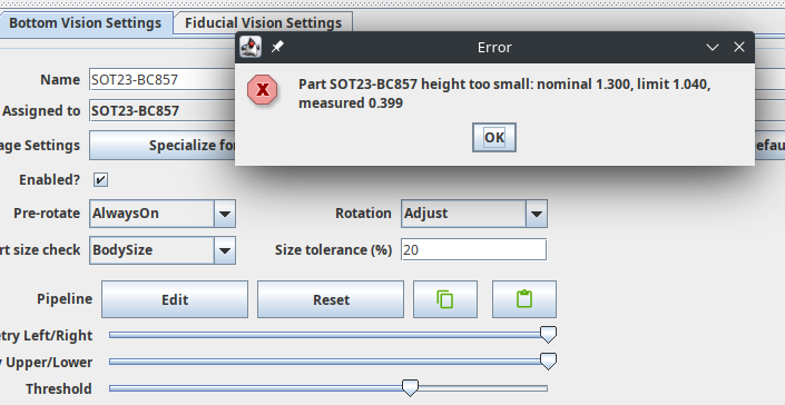
> check on this part, and got the same issues with height (height on this
> package is set to 1.000);
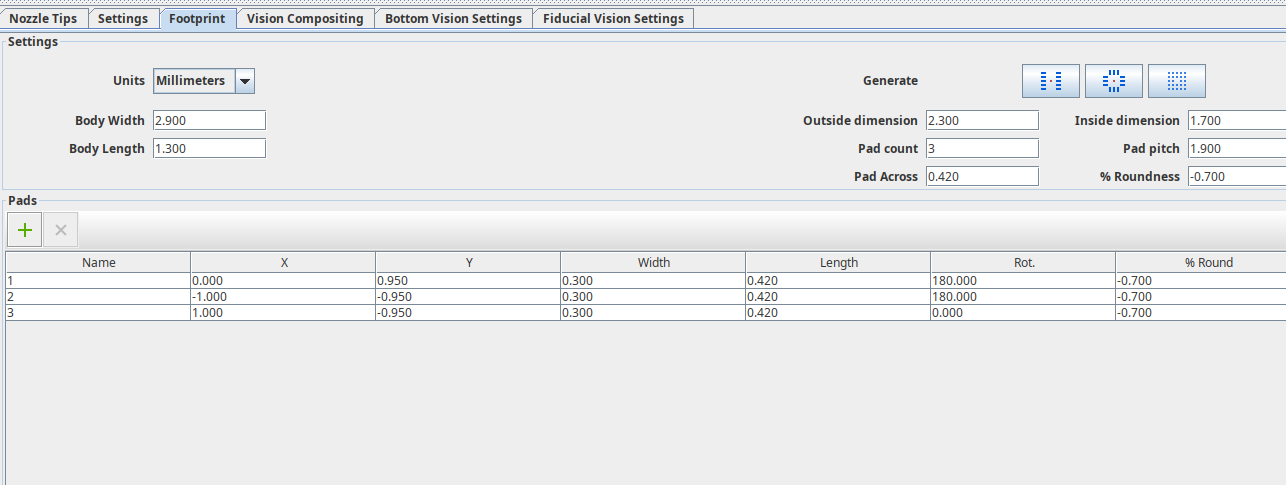
> What am I missing? Is height actually height, or is it "Body length"
> (which incidentally is 1.300 on this package)?
as part of the footprint of the package are compared against the image
you have after all image processing has been done. Usually you then only
have the pins visible. I'm using the "Part size check" method
"PadExtents" with the default tolerance of 20%.
Jan
> onsdag 29 mars 2023 kl. 17:28:02 UTC+2 skrev vespaman:
>
> So, a day progress, thanks to the both of you! :-)
>
> I have done a few parts now, and it looks rather nice.
>
> Mark, here's a few input from me, that may be in the doc, but I have
> missed, or misread;
>
> 1. I have all my packages with footprint and composition (I did them
> before, when importing the board data). This seems to have great
> input to the result of the bottom vision, and I guess I had not
> (still haven't, for sure!) understood exactly everything correctly
> in that part of the package setup. If not mentioned in the bottom
> vision text (and I have missed it), maybe it would be good to
> mention that it also is part of the equation.
>
> 2. I realize the problem with keeping the docs both updated, as well
> as keeping the old parts, but it is still rather easy to "read
> through" into the old, obsolete part.
> Not sure what the solution is here, but perhaps put a different
> colour background on the older part? Anyway, maybe this is part of
> something bigger.
>
> 3. If the machine setup->vision is still needed, (which I guess it
> might be after all given your response to Jan, with pictures and
> all!) (I happily went along with Jans suggestion that it was
> superseded by the top vision tab, and have not used it so far today).
> Anyway, the
>
>
> - Micael
>
>
> onsdag 29 mars 2023 kl. 16:25:12 UTC+2 skrev ma...@makr.zone:
>
> Hi Jan,
>
> (unlike the others with the "-") is *not *a factory setting, but
> configuration when the system upgraded OpenPnP to the Vision
> Settings system. For new configurations it is identical to the
> Stock settings, but already cloned so it can be edited.
>
> Stock (or other) settings, press *Copy* and press *Paste*:
> Then you can rename the Copy as you like in the table cell (F2)
>
> Is this needed in the Wiki?
>
> I considered this rather generic OpenPnP GUI usage, but
> certainly my "developer viewpoint" is not to be trusted 😅
>
> information/, where you lose your readers before they went
> through the important stuff, and /too little/ 😎
>>> --
>>> You received this message because you are subscribed to the
>>> Google Groups "OpenPnP" group.
>>> To unsubscribe from this group and stop receiving emails from
>>> it, send an email to openpnp+u...@googlegroups.com
>>> <mailto:openpnp+u...@googlegroups.com>.
>>> To view this discussion on the web visit
> --
> You received this message because you are subscribed to the Google
> Groups "OpenPnP" group.
> To unsubscribe from this group and stop receiving emails from it, send
> an email to openpnp+u...@googlegroups.com
> <mailto:openpnp+u...@googlegroups.com>.
> To view this discussion on the web visit
mark maker
> Unfortunately it will make the process slower because it
requires two pictures at different positions.
True, but because the move is very short, I expect it to be quite fast for that not-so-large SOT23, not much more than any normal vision iteration. It would be nice if Micael could actually provide his log, so we see how much time it costs.
On the other hand: some SOT23 are huge with 1.9 millimeter pitch
and often generous solder pads, are you sure you need bottom
vision at all? AFAIK, reflow aligns such parts nicely.
> A better solution for SOT23 and alike would be to implement rotated pattern matching
Yeah image or even just footprint pattern matching would solve it. But unfortunately there is no "Match Template With Rotation" OpenCV routine, otherwise I would probably have implemented it a long time ago.
The DetectRectlinearSymmetry computation time problem actually
warned me off trying in java (for now). I am toying with
some ideas...
_Mark
vespaman
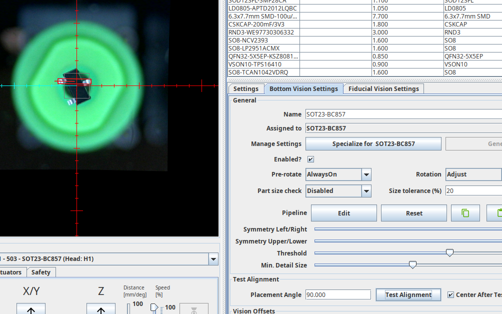
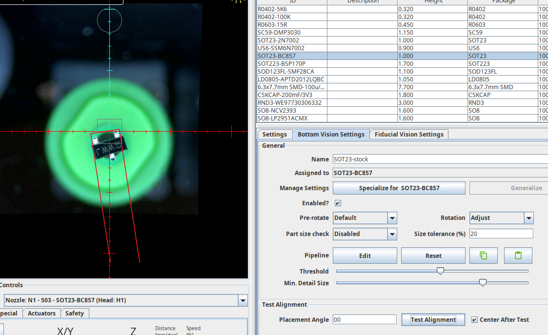
Hi Jan,
> Actually, while I was grabbing screenshots, I also activated part size
> check on this part, and got the same issues with height (height on this
> package is set to 1.000);
> What am I missing? Is height actually height, or is it "Body length"
> (which incidentally is 1.300 on this package)?
Please keep in mind, that the part size (width and height) you provide
as part of the footprint of the package are compared against the image
you have after all image processing has been done. Usually you then only
have the pins visible. I'm using the "Part size check" method
"PadExtents" with the default tolerance of 20%.
vespaman
mark maker
> But if it is actually using the dimensions from the
footprint page, it should be width and length, right? Height (Z)
is something else.
> In this case, the error message has a flaw.
vespaman
mark maker
Please send a native camera snapsot file and your camera Units per Pixel.
_Mark
--
You received this message because you are subscribed to the Google Groups "OpenPnP" group.
To unsubscribe from this group and stop receiving emails from it, send an email to openpnp+u...@googlegroups.com.
To view this discussion on the web visit https://groups.google.com/d/msgid/openpnp/4d9097d4-a2a0-43d1-907b-7cb54858de77n%40googlegroups.com.
vespaman
vespaman

vespaman

Mike Menci
mark maker
This should work using a Stock pipeline, and multi-shot bottom
vision. You need to generate the footprint which is easy.
Best watch the whole video:
_Mark
--
You received this message because you are subscribed to the Google Groups "OpenPnP" group.
To unsubscribe from this group and stop receiving emails from it, send an email to openpnp+u...@googlegroups.com.
To view this discussion on the web visit https://groups.google.com/d/msgid/openpnp/e1aca268-14e5-468b-8365-d0c2b6fcfeddn%40googlegroups.com.
vespaman
vespaman
Best watch the whole video:
vespaman
mark maker
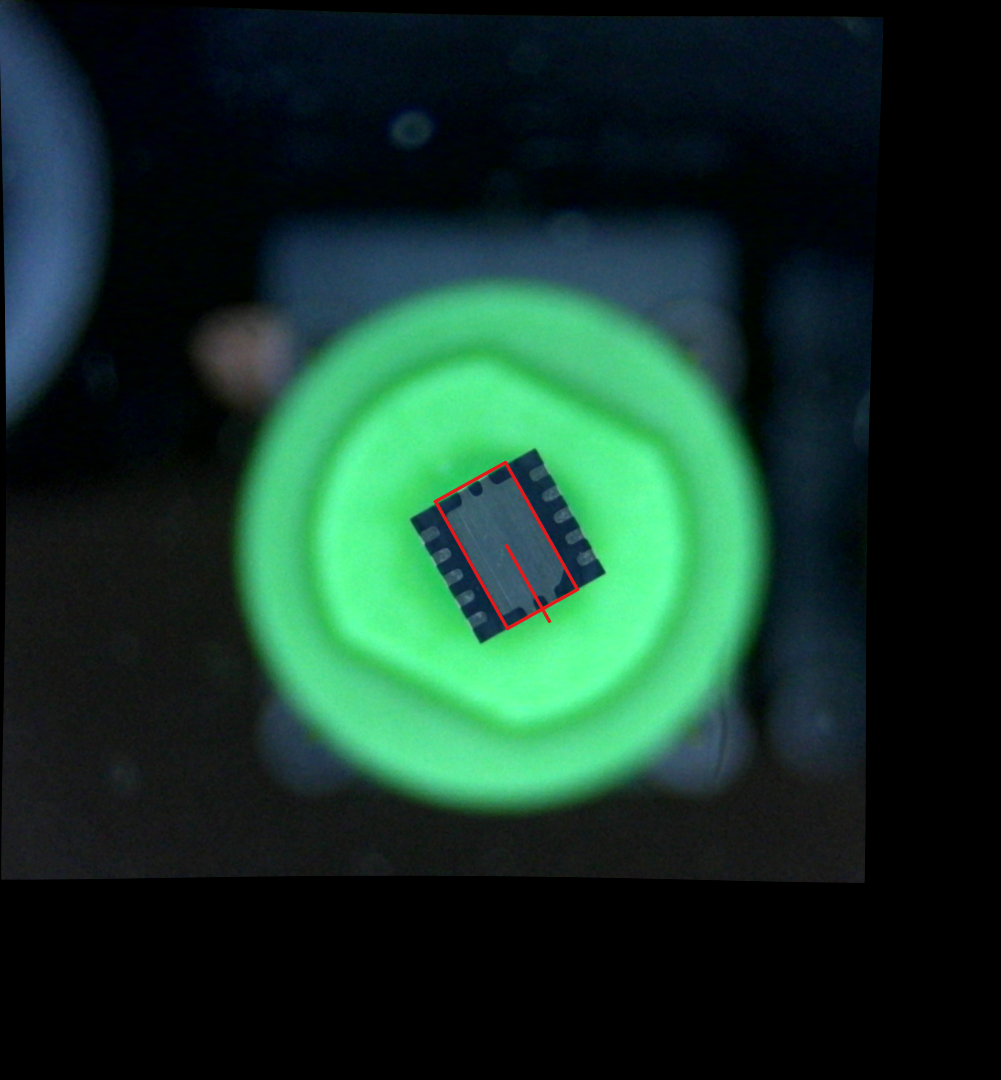
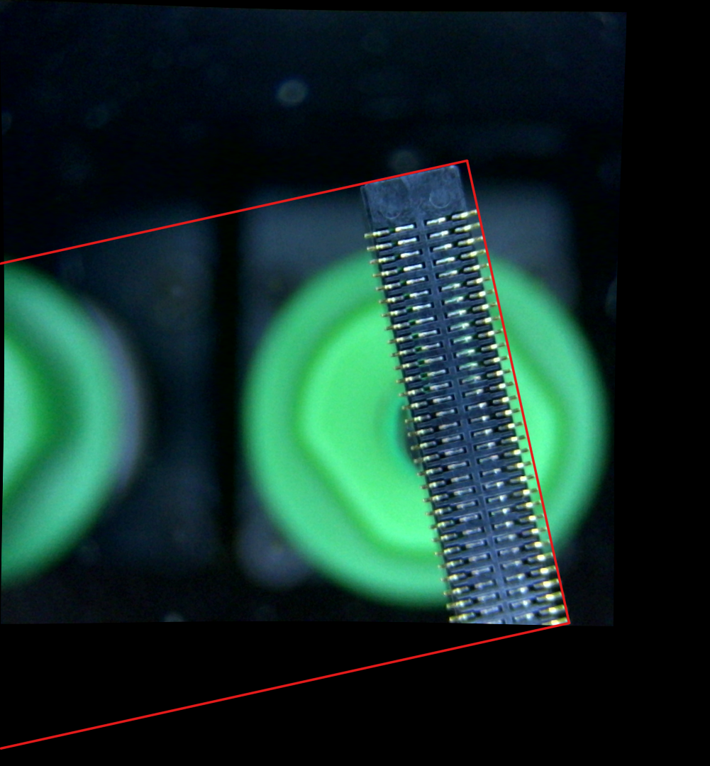
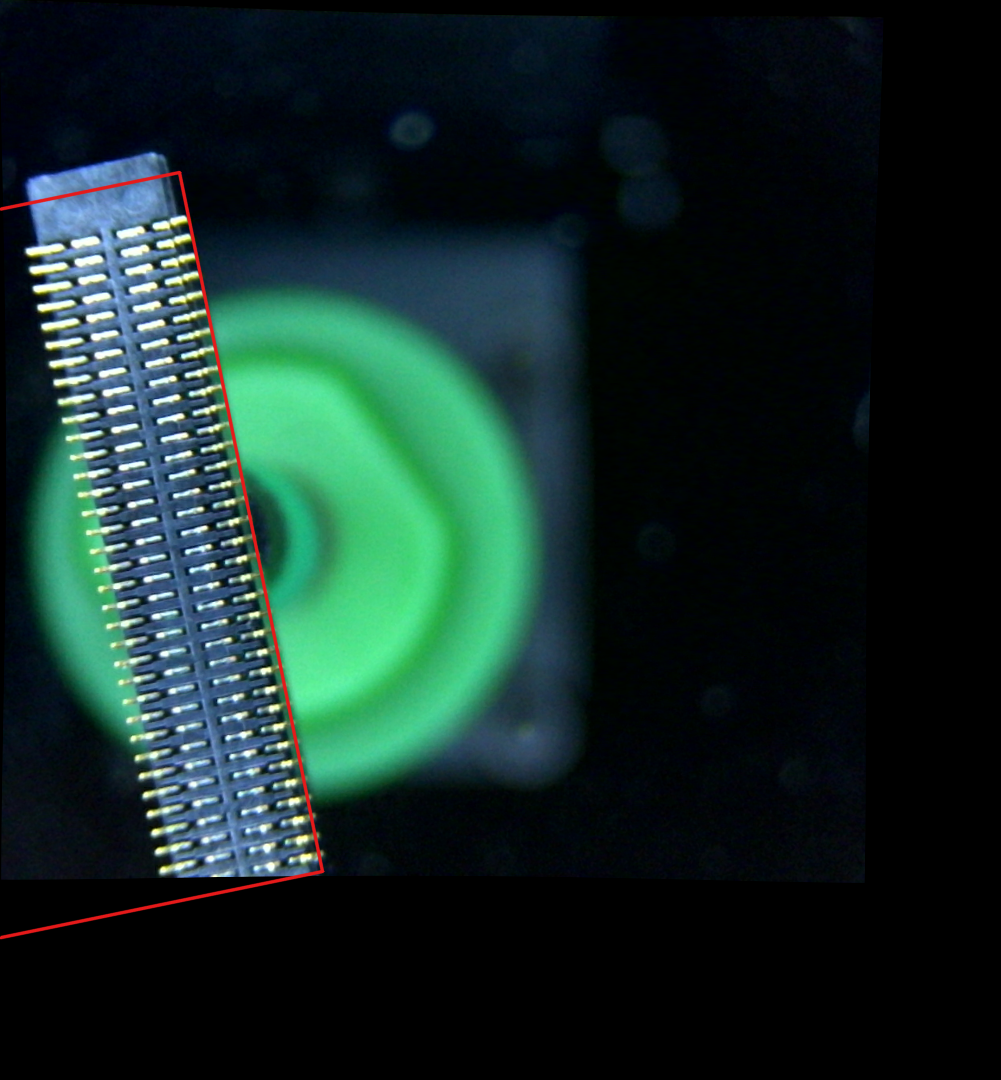
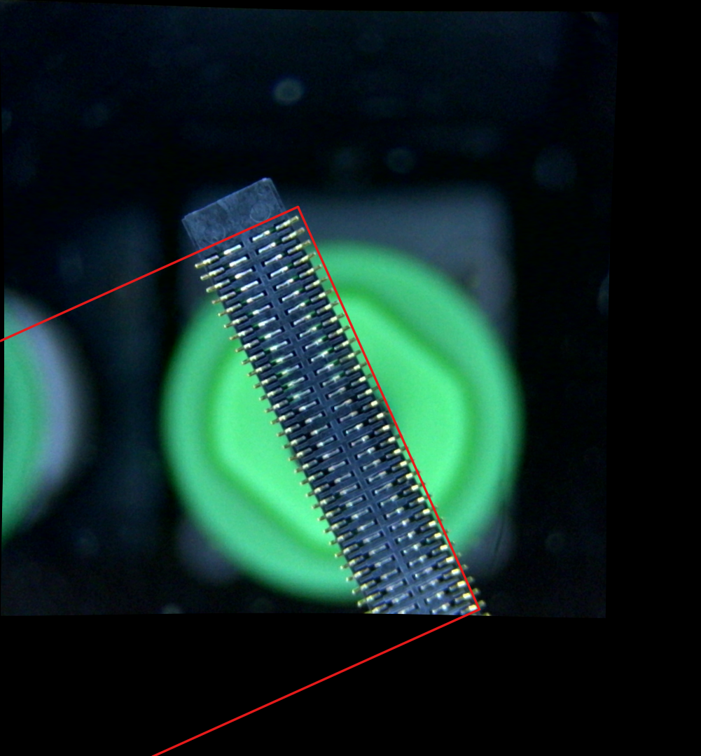
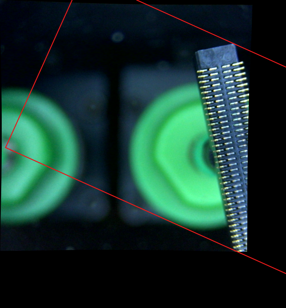
> Could it be that the tray feeder, which does not seem to have a "rotation in tape" setting is part of the problem?
Yes that was my initial guess when I saw your image, because you already had the bracket rectangle but from the wrong side. But then you did not mention multi-shot, so I thought I was mistaken.
Also check the max. part diameter on the nozzle tip. With the bracketing going out so far, I guess it is too large.
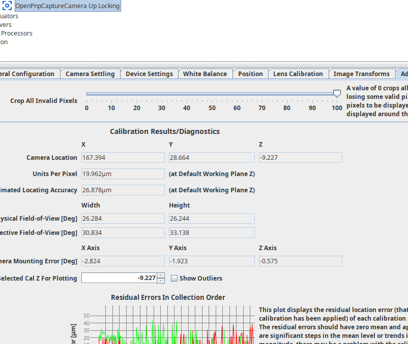
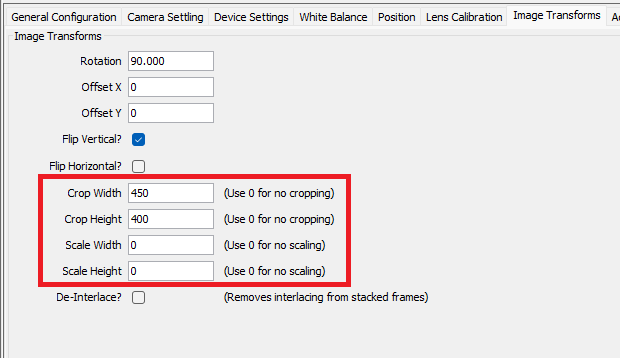
Also: I always recommend cropping the camera image to "only valid pixels" in Advanced Camera Calibration (slider all the way). So the black margins go away. They fool Multi-shot into thinking it can use this margin area, when in fact it is partly black.
(if it was for me, I would make this the default, or even remove
that slider).
_Mark
--
You received this message because you are subscribed to the Google Groups "OpenPnP" group.
To unsubscribe from this group and stop receiving emails from it, send an email to openpnp+u...@googlegroups.com.
To view this discussion on the web visit https://groups.google.com/d/msgid/openpnp/d7d8dba3-a978-4afa-b504-4151b2cb3750n%40googlegroups.com.
vespaman
> Could it be that the tray feeder, which does not seem to have a "rotation in tape" setting is part of the problem?
Also check the max. part diameter on the nozzle tip. With the bracketing going out so far, I guess it is too large.
Also: I always recommend cropping the camera image to "only valid pixels" in Advanced Camera Calibration (slider all the way). So the black margins go away. They fool Multi-shot into thinking it can use this margin area, when in fact it is partly black.
mark maker
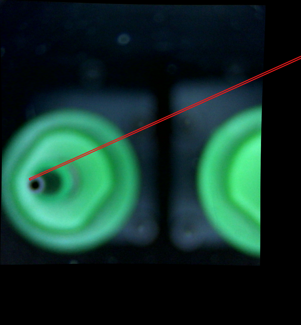
> It is set to 20, this part is about 18 (diagonal), so I guess it should be ok?
It is for parts that fit inside the camera view. For larger parts and multi-shot it controls the max mask diameter of the corner/bracket shots.
But if you set the camera to "only valid pixels" it does not matter if you set it too large, OpenPnP will always reduce it to the smaller camera dimension.
> So, it is better, but not good enough. I would not try to place it on a real board. I _think_ this may be because the pins are not flat, so the reflection of them is different depending on the camera angle
Yes the pins are very thin, rounded and angled, so reflection is
bad. Maybe a larger/bowl shaped diffuser would help, so strong
light comes from a wider range of angles.
You have played with the Threshold and Min. Detail
Size sliders, right?
_Mark
--
You received this message because you are subscribed to the Google Groups "OpenPnP" group.
To unsubscribe from this group and stop receiving emails from it, send an email to openpnp+u...@googlegroups.com.
To view this discussion on the web visit https://groups.google.com/d/msgid/openpnp/c058a4e3-41a4-45b7-b8ad-3694993b9580n%40googlegroups.com.